2006 MERCEDES-BENZ SPRINTER relay
[x] Cancel search: relayPage 382 of 2305

TEST ACTION APPLICABILITY
3 Turn the ignition off.
Disconnect the CAB harness connector.
Inspect the CAB/CAB harness connector for damage.
Is there any broken, bent, pushed out, corroded or spread terminals?All
Ye s!Repair as necessary.
Perform ABS VERIFICATION TEST - VER 1.
No!Go To 4
4 Turn the ignition off.
Turn the ignition on.
With the DRBIIItin Sensors, read the Relay Output voltage.
Start the engine.
With the DRBIIItin Sensors, read the Relay Output voltage.
Select the Relay Output voltage that was displayed on the DRBIIIt.All
Voltage below 9.4 volts.
Go To 5
Voltage above 17.4 volts.
Go To 7
Voltage between 9.4 and 17.4 volts.
Go To 8
5 Turn the ignition off.
Disconnect the CAB harness connector.
Start the engine.
Allow the engine to idle.
WARNING: WHEN THE ENGINE IS OPERATING, DO NOT STAND IN A
DIRECT LINE WITH THE FAN. DO NOT PUT YOUR HANDS NEAR THE
PULLEYS, BELTS OR FAN. DO NOT WEAR LOOSE CLOTHING.
Measure the voltage of the Fused Optional Equipment Relay Output circuit in the
CAB harness connector.
Raise the engine speed above 2,000 RPM's.
Measure the voltage of the Fused Optional Equipment Relay Output circuit in the
CAB harness connector.
Is the voltage less than 9.4 volts?All
Ye s!Repair the Fused Optional Equipment Relay Output circuit for an
open.
Perform ABS VERIFICATION TEST - VER 1.
No!Go To 6
61
BRAKES (CAB)
RELAY OUTPUT VOLTAGE ÐContinued
Page 383 of 2305

TEST ACTION APPLICABILITY
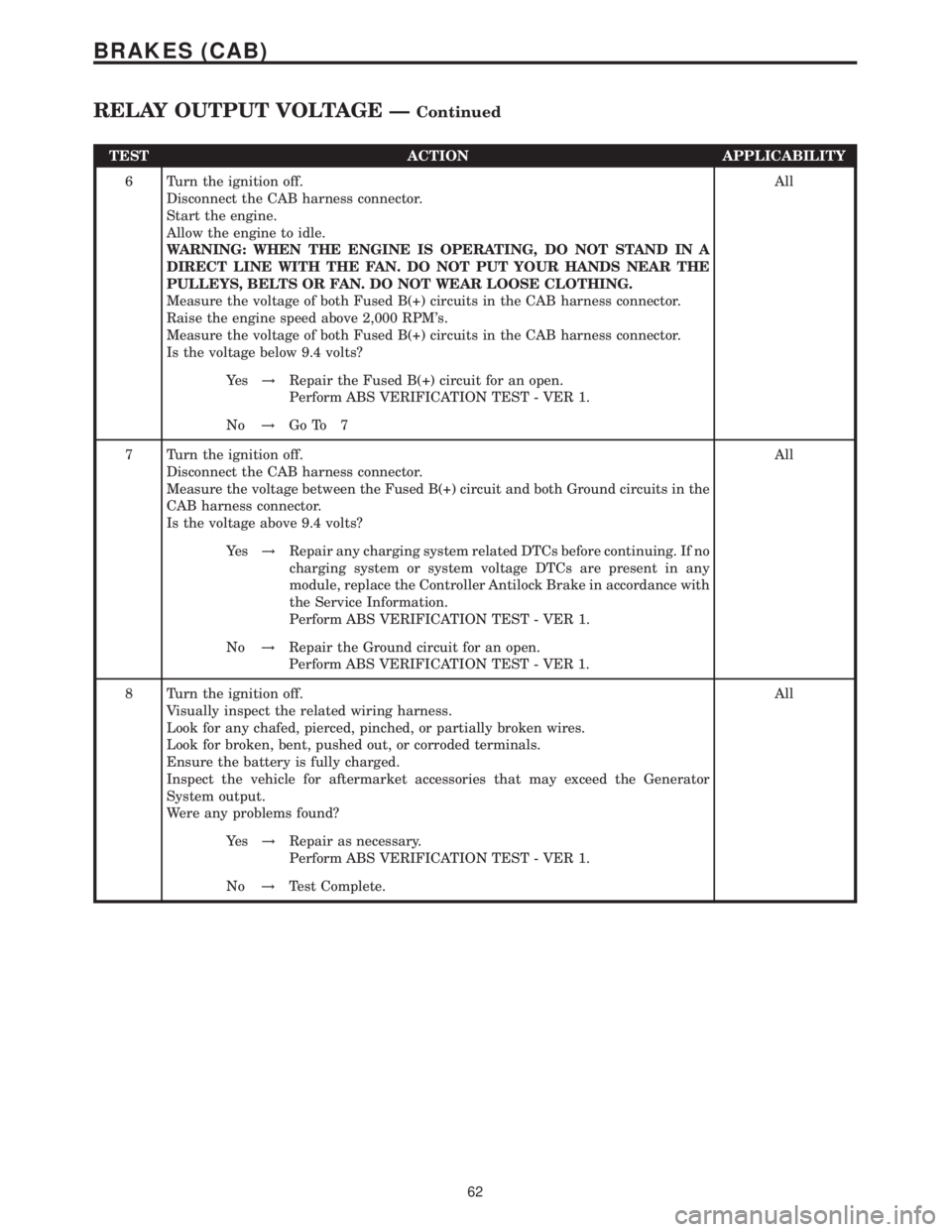
6 Turn the ignition off.
Disconnect the CAB harness connector.
Start the engine.
Allow the engine to idle.
WARNING: WHEN THE ENGINE IS OPERATING, DO NOT STAND IN A
DIRECT LINE WITH THE FAN. DO NOT PUT YOUR HANDS NEAR THE
PULLEYS, BELTS OR FAN. DO NOT WEAR LOOSE CLOTHING.
Measure the voltage of both Fused B(+) circuits in the CAB harness connector.
Raise the engine speed above 2,000 RPM's.
Measure the voltage of both Fused B(+) circuits in the CAB harness connector.
Is the voltage below 9.4 volts?All
Ye s!Repair the Fused B(+) circuit for an open.
Perform ABS VERIFICATION TEST - VER 1.
No!Go To 7
7 Turn the ignition off.
Disconnect the CAB harness connector.
Measure the voltage between the Fused B(+) circuit and both Ground circuits in the
CAB harness connector.
Is the voltage above 9.4 volts?All
Ye s!Repair any charging system related DTCs before continuing. If no
charging system or system voltage DTCs are present in any
module, replace the Controller Antilock Brake in accordance with
the Service Information.
Perform ABS VERIFICATION TEST - VER 1.
No!Repair the Ground circuit for an open.
Perform ABS VERIFICATION TEST - VER 1.
8 Turn the ignition off.
Visually inspect the related wiring harness.
Look for any chafed, pierced, pinched, or partially broken wires.
Look for broken, bent, pushed out, or corroded terminals.
Ensure the battery is fully charged.
Inspect the vehicle for aftermarket accessories that may exceed the Generator
System output.
Were any problems found?All
Ye s!Repair as necessary.
Perform ABS VERIFICATION TEST - VER 1.
No!Test Complete.
62
BRAKES (CAB)
RELAY OUTPUT VOLTAGE ÐContinued
Page 384 of 2305

Symptom:
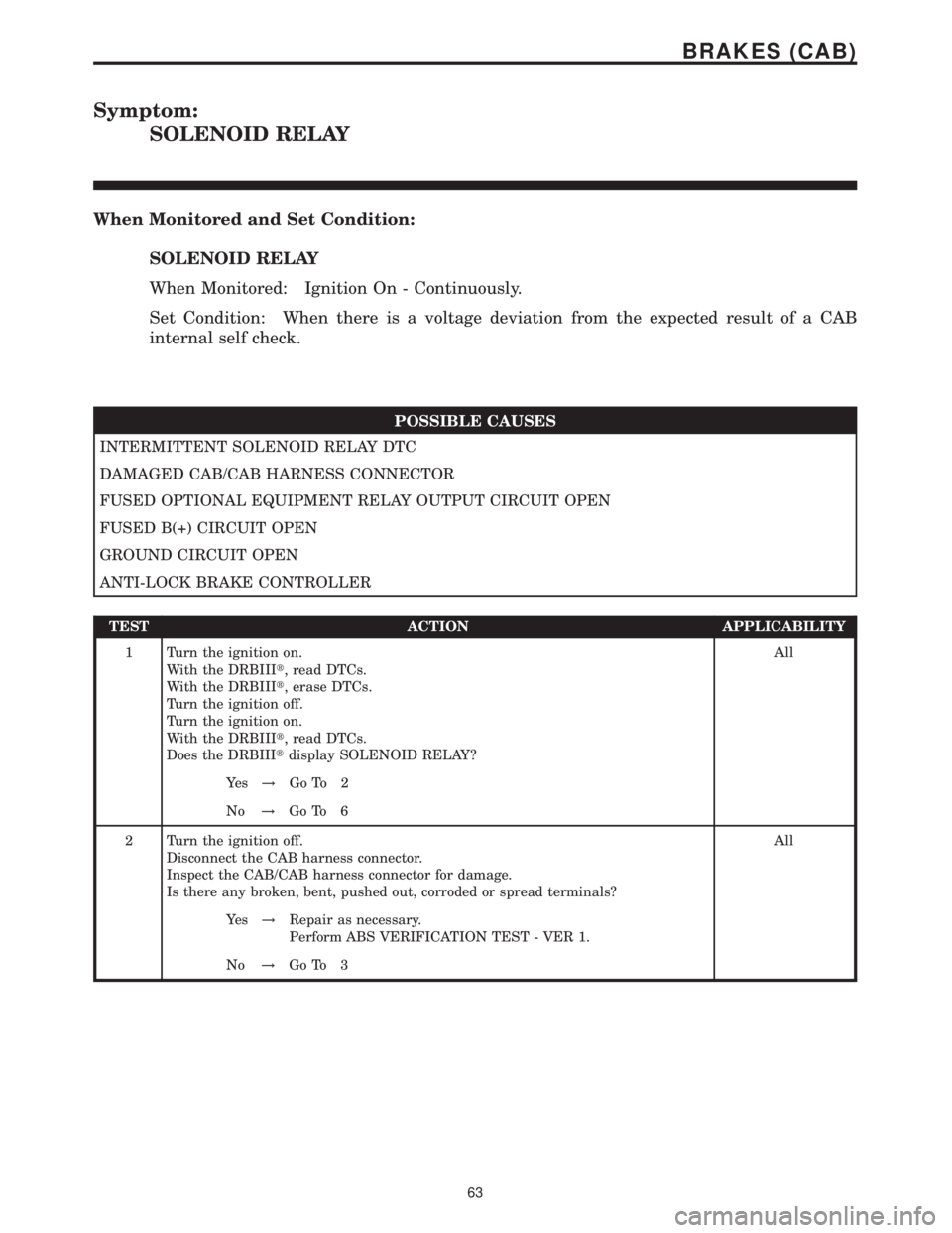
SOLENOID RELAY
When Monitored and Set Condition:
SOLENOID RELAY
When Monitored: Ignition On - Continuously.
Set Condition: When there is a voltage deviation from the expected result of a CAB
internal self check.
POSSIBLE CAUSES
INTERMITTENT SOLENOID RELAY DTC
DAMAGED CAB/CAB HARNESS CONNECTOR
FUSED OPTIONAL EQUIPMENT RELAY OUTPUT CIRCUIT OPEN
FUSED B(+) CIRCUIT OPEN
GROUND CIRCUIT OPEN
ANTI-LOCK BRAKE CONTROLLER
TEST ACTION APPLICABILITY
1 Turn the ignition on.
With the DRBIIIt, read DTCs.
With the DRBIIIt, erase DTCs.
Turn the ignition off.
Turn the ignition on.
With the DRBIIIt, read DTCs.
Does the DRBIIItdisplay SOLENOID RELAY?All
Ye s!Go To 2
No!Go To 6
2 Turn the ignition off.
Disconnect the CAB harness connector.
Inspect the CAB/CAB harness connector for damage.
Is there any broken, bent, pushed out, corroded or spread terminals?All
Ye s!Repair as necessary.
Perform ABS VERIFICATION TEST - VER 1.
No!Go To 3
63
BRAKES (CAB)
Page 385 of 2305

TEST ACTION APPLICABILITY
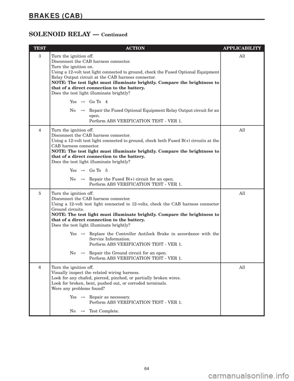
3 Turn the ignition off.
Disconnect the CAB harness connector.
Turn the ignition on.
Using a 12-volt test light connected to ground, check the Fused Optional Equipment
Relay Output circuit at the CAB harness connector.
NOTE: The test light must illuminate brightly. Compare the brightness to
that of a direct connection to the battery.
Does the test light illuminate brightly?All
Ye s!Go To 4
No!Repair the Fused Optional Equipment Relay Output circuit for an
open.
Perform ABS VERIFICATION TEST - VER 1.
4 Turn the ignition off.
Disconnect the CAB harness connector.
Using a 12-volt test light connected to ground, check both Fused B(+) circuits at the
CAB harness connector.
NOTE: The test light must illuminate brightly. Compare the brightness to
that of a direct connection to the battery.
Does the test light illuminate brightly?All
Ye s!Go To 5
No!Repair the Fused B(+) circuit for an open.
Perform ABS VERIFICATION TEST - VER 1.
5 Turn the ignition off.
Disconnect the CAB harness connector.
Using a 12-volt test light connected to 12-volts, check the CAB harness connector
Ground circuits.
NOTE: The test light must illuminate brightly. Compare the brightness to
that of a direct connection to the battery.
Does the test light illuminate brightly?All
Ye s!Replace the Controller Antilock Brake in accordance with the
Service Information.
Perform ABS VERIFICATION TEST - VER 1.
No!Repair the Ground circuit for an open.
Perform ABS VERIFICATION TEST - VER 1.
6 Turn the ignition off.
Visually inspect the related wiring harness.
Look for any chafed, pierced, pinched, or partially broken wires.
Look for broken, bent, pushed out, or corroded terminals.
Were any problems found?All
Ye s!Repair as necessary.
Perform ABS VERIFICATION TEST - VER 1.
No!Test Complete.
64
BRAKES (CAB)
SOLENOID RELAY ÐContinued
Page 398 of 2305

Symptom:
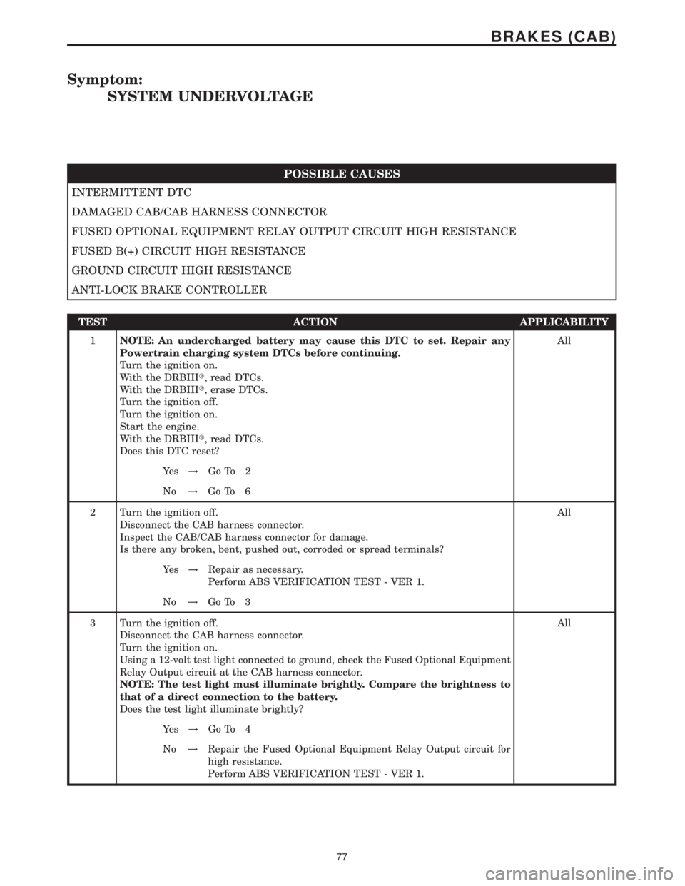
SYSTEM UNDERVOLTAGE
POSSIBLE CAUSES
INTERMITTENT DTC
DAMAGED CAB/CAB HARNESS CONNECTOR
FUSED OPTIONAL EQUIPMENT RELAY OUTPUT CIRCUIT HIGH RESISTANCE
FUSED B(+) CIRCUIT HIGH RESISTANCE
GROUND CIRCUIT HIGH RESISTANCE
ANTI-LOCK BRAKE CONTROLLER
TEST ACTION APPLICABILITY
1NOTE: An undercharged battery may cause this DTC to set. Repair any
Powertrain charging system DTCs before continuing.
Turn the ignition on.
With the DRBIIIt, read DTCs.
With the DRBIIIt, erase DTCs.
Turn the ignition off.
Turn the ignition on.
Start the engine.
With the DRBIIIt, read DTCs.
Does this DTC reset?All
Ye s!Go To 2
No!Go To 6
2 Turn the ignition off.
Disconnect the CAB harness connector.
Inspect the CAB/CAB harness connector for damage.
Is there any broken, bent, pushed out, corroded or spread terminals?All
Ye s!Repair as necessary.
Perform ABS VERIFICATION TEST - VER 1.
No!Go To 3
3 Turn the ignition off.
Disconnect the CAB harness connector.
Turn the ignition on.
Using a 12-volt test light connected to ground, check the Fused Optional Equipment
Relay Output circuit at the CAB harness connector.
NOTE: The test light must illuminate brightly. Compare the brightness to
that of a direct connection to the battery.
Does the test light illuminate brightly?All
Ye s!Go To 4
No!Repair the Fused Optional Equipment Relay Output circuit for
high resistance.
Perform ABS VERIFICATION TEST - VER 1.
77
BRAKES (CAB)
Page 405 of 2305

CONTROLLER ANTILOCK BRAKECAV CIRCUIT FUNCTION
1 12BR GROUND
2 12RD FUSED B(+)
3- -
4- -
5 14BR GROUND
6 14RD FUSED B(+)
7- -
8 20BK/DG SENSOR SIGNAL
9 20YL/WT SENSOR SIGNAL
10 20YL/RD SENSOR SIGNAL
11 18BL/BK K-ABS/SHIFTER ASSEMBLY
12 18BK LEFT FRONT WHEEL SPEED SENSOR (+)
13 - -
14 20WT LEFT REAR WHEEL SPEED SENSOR (+)
15 18BR RIGHT FRONT WHEEL SPEED SENSOR (-)
16 18BK RIGHT FRONT WHEEL SPEED SENSOR (+)
17 - -
18 - -
19 - -
20 20WT BRAKE SWITCH OUTPUT
21 20BR GROUND
22 - -
23 18BK/RD FUSED OPTIONAL EQUIPMENT RELAY OUTPUT
24 20DG/WT CAN C BUS (+)
25 20BR SENSOR GROUND
26 20WT/GY BRAKE PRESSURE SENSOR SIGNAL
27 18BK/BL TCS SWITCH (ASR) SENSE
28 18BR LEFT FRONT WHEEL SPEED SENSOR (-)
29 20BR LEFT REAR WHEEL SPEED SENSOR (-)
30 20BR RIGHT REAR WHEEL SPEED SENSOR (-)
31 20YL RIGHT REAR WHEEL SPEED SENSOR (+)
32 18BK/RD BRAKE LAMP SWITCH OUTPUT
33 - -
34 - -
35 - -
36 - -
37 - -
38 - -
39 20RD/BL POWER INPUT
40 20DG CAN C BUS (-)
41 20DG/YL SENSOR SIGNAL
42 20WT/RD 5 VOLT SUPPLY
C
O
N
N
E
C
T
O
R
P
I
N
O
U
T
S
84
CONNECTOR PINOUTS
Page 406 of 2305

INSTRUMENT CLUSTER C2 - WHITECAV CIRCUIT FUNCTION
1- -
2- -
3 20RD/YL FUSED B(+)
4 20BR/WT BRAKE WEAR SENSOR SIGNAL
5- -
6 18BR GROUND
7 20GY/DG/RD LAMP DRIVER
8 20BL/WT FUSED HIGH BEAM SWITCH OUTPUT
9 20BL/RD/WT VEHICLE SPEED SENSOR OUTPUT
10 20BK FUSED IGNITION SWITCH OUTPUT (RUN-START)
11 20BL/BK KEY-IN IGNITION SWITCH SIGNAL
12 - -
13 20BK/WT LEFT TURN SIGNAL
14 20BR/YL BRAKE FLUID LEVEL INDICATOR SIGNAL
15 20BL GENERATOR FIELD DRIVER
16 20YL AIRBAG WARNING INDICATOR DRIVER
17 - -
18 20BL/VT D(+) RELAY NO. 1 CONTROL
18 20BL/VT D(+) RELAY NO. 1 CONTROL
STEERING ANGLE SENSORCAV CIRCUIT FUNCTION
1 20DG/WT CAN C BUS (-)
2- -
3 20DG CAN C BUS (+)
4- -
5 20BK/RD FUSED OPTIONAL EQUIPMENT RELAY OUTPUT
6 20BR GROUND
TCS SWITCH (ASR) - BLACKCAV CIRCUIT FUNCTION
1 16GY/DG/RD LAMP DRIVER
2- -
3 18BK/BL TCS SWITCH (ASR) SENSE
4- -
5- -
6- -
7 16BK/BL/DG FUSED IGNITION SWITCH OUTPUT
8- -
9- -
10 16BR GROUND
WHEEL SPEED SENSOR-LEFT FRONTCAV CIRCUIT FUNCTION
1 18BK LEFT FRONT WHEEL SPEED SENSOR (+)
2 18BR LEFT FRONT WHEEL SPEED SENSOR (-)
C
O
N
N
E
C
T
O
R
P
I
N
O
U
T
S
85
CONNECTOR PINOUTS
Page 413 of 2305

TABLE OF CONTENTS - Continued
P1617- ECM WRITE ERROR..............................................16
P1617-ECM INCORRECT VALUE..........................................16
P1617-ECM READ ERROR...............................................16
P2122-INTERNAL ERROR COUNTER FAULT................................16
P2122-INTERNAL ERROR ENGINE SHUT OFF..............................16
P2122-INTERNAL ERROR ENGINE VOLTAGE MONITORING...................16
P2122-INTERNAL ERROR ENGINE VOLTAGE MONITORING...................16
P2123-INJECTOR BANK ERROR..........................................16
P2124-INJECTOR BANK ERROR..........................................16
P2139-ECM INJECTOR OUTPUT STAGE #1.................................16
P2139-ECM INJECTOR OUTPUT STAGE #1 SHORT CIRCUIT..................16
P2140-ECM INJECTOR OUTPUT STAGE #2.................................16
P2140-ECM INJECTOR OUTPUT STAGE #2 SHORT CIRCUIT..................16
P2149-ECM A/D CONVERTER HIGH.......................................16
P2149-ECM A/D CONVERTER LOW........................................16
P2149-ECM A/D CONVERTER PLAUSIBILITY................................16
P2153-STARTER RELAY CIRCUIT ECM THERMAL OVERLOAD................16
P2197-FUEL QUANTITY SOLENOID ECM THERMAL OVERLOAD...............16
P2214-CAN MESSAGE ERROR...........................................16
P2319-ECM INTERNAL ERROR 1..........................................16
P2319-ECM INTERNAL ERROR 2..........................................16
P2319-ECM INTERNAL ERROR 3..........................................16
P2319-ECM INTERNAL ERROR 4..........................................16
P2321-ECM INTERNAL ERROR 5..........................................16
P2323-ECM INTERNAL ERROR...........................................16
P2324-ECM INJECTOR MONITORING 1....................................16
P2324-ECM INJECTOR MONITORING 2....................................16
P2324-ECM INJECTOR MONITORING 3....................................16
P2324-ECM INJECTOR MONITORING 4....................................16
P2324-ECM INJECTOR UNDERVOLTAGE...................................16
P2325-ECM INTERNAL ERROR 1..........................................16
P2325-ECM INTERNAL ERROR 2..........................................16
P2325-ECM INTERNAL ERROR 3..........................................16
P2325-ECM INTERNAL ERROR 4..........................................16
P2329-ECM INTERNAL ERROR 1..........................................16
P2330-ECM INTERNAL ERROR 1..........................................16
P2340-ECM INJECTION QUANTITY ERROR.................................16
P2342-ECM INTERNAL ERROR 1..........................................16
P2342-ECM INTERNAL ERROR 2..........................................17
P2350-INTERNAL VOLTAGE ERROR.......................................17
P2352-INJECTION FAULT - EXCESSIVE TEMPERATURE......................17
P2352-INJECTION FAULT - QUANTITY ERROR..............................17
P2352-INJECTION FAULT - TORQUE LIMIT.................................17
P2352-INJECTION FAULT EXCESSIVE ENGINE SPEED.......................17
P2354-ECM INTERNAL FAULT............................................17
P2356-ECM INTERNAL ERROR...........................................17
P2357-ECM INTERNAL ERROR...........................................17
P2358-ECM INTERNAL ERROR...........................................17
P2500-FUEL PRESSURE SOLENOID CIRCUIT EXCESSIVE CURRENT..........17
P2514-CRANKCASE VENT HEATER EXCESSIVE CURRENT...................17
P2526-BOOST PRESSURE SERVO MOTOR EXCESSIVE CURRENT............17
P2527-EGR VALVE EXCESSIVE CURRENT.................................17
P0100-MASS AIR FLOW SENSOR SIGNAL VOLTAGE TOO LOW...............19
ii