2006 MERCEDES-BENZ SPRINTER service indicator
[x] Cancel search: service indicatorPage 999 of 2305

restraint system is functioning normally and that the
repairs are complete. If the airbag indicator fails to
light, or lights and stays on, there is still an active
supplemental restraint system fault or malfunction.
Refer to the appropriate diagnostic information to
diagnose the problem.
NOTE: If the Airbag Control Module (ACM) has been
replaced with a new unit, it will be necessary to ini-
tialize the new ACM. In order to function properly,
the ACM must be programmed for the correct stan-
dard and optional supplemental restraint system
components installed in the vehicle. To initialize the
ACM, a diagnostic scan tool is required. Refer to
the appropriate diagnostic information.
AIRBAG CONTROL MODULE
DESCRIPTION
The Airbag Control Module (ACM) is secured with
three screws to the top mounting surface of a
stamped steel bracket that is welded onto the floor
panel within the seat riser underneath the driver
side front seat in the passenger compartment of the
vehicle (Fig. 6). A molded plastic protective cover is
installed over the ACM and secured with integral
snap features to a flat metal base plate sandwiched
between the bottom of the ACM and the mounting
bracket on the floor panel (Fig. 7). This cover is
designed to shield the ACM and its wire harness con-
nection from other electrical components and wiring
located within the seat riser area beneath the driver
seat, and must always be reinstalled following ser-
vice removal.Concealed within a hollow in the center of the die
cast aluminum ACM housing is the electronic cir-
cuitry of the ACM which includes a microprocessor,
an electronic impact sensor, an electronic safing sen-
sor, and an energy storage capacitor. A stamped
metal cover plate is permanently secured to the bot-
tom of the ACM housing to enclose and protect the
internal electronic circuitry and components.
An arrow printed on a label on the top of the ACM
housing near the rear provides a visual verification
of the proper orientation of the unit, and should
always be pointed toward the front of the vehicle.
The ACM housing has integral mounting flanges on
three corners. A molded plastic electrical connector
receptacle containing numerous terminal pins is inte-
gral to the left facing side of the ACM housing. These
terminal pins connect the ACM to the vehicle electri-
cal system through a dedicated take out and connec-
tor of the vehicle wire harness.
The impact sensor internal to the ACM are cali-
brated for the specific vehicle, and are only serviced
as a unit with the ACM. In addition, the ACM must
be electronically programmed for the correct stan-
dard and optional supplemental restraint system
components installed in the vehicle. The ACM cannot
be repaired or adjusted and, if damaged or faulty, it
must be replaced.
OPERATION
The microprocessor in the Airbag Control Module
(ACM) contains the supplemental restraint system
logic circuits and controls all of the supplemental
restraint system components. The ACM uses
On-Board Diagnostics (OBD) and can communicate
with a diagnostic scan tool using a diagnostic Serial
Fig. 6 Airbag Control Module
1 - AIRBAG CONTROL MODULE
2 - LABEL
3 - ORIENTATION ARROW
4 - CONNECTOR RECEPTACLE
Fig. 7 ACM Bracket
1 - ACM BRACKET
2 - SEAT RISER
3 - EYELET TERMINAL
4 - ACM CONNECTOR
5 - FLOOR PANEL
8O - 8 RESTRAINTSVA
Page 1024 of 2305
deployment. A growling or grinding sound while
attempting to operate the seat belt retractor is a sure
indication that the seat belt tensioner has been
deployed and requires replacement. (Refer to 8 -
ELECTRICAL/RESTRAINTS/FRONT SEAT BELT &
RETRACTOR - REMOVAL).
OPERATION
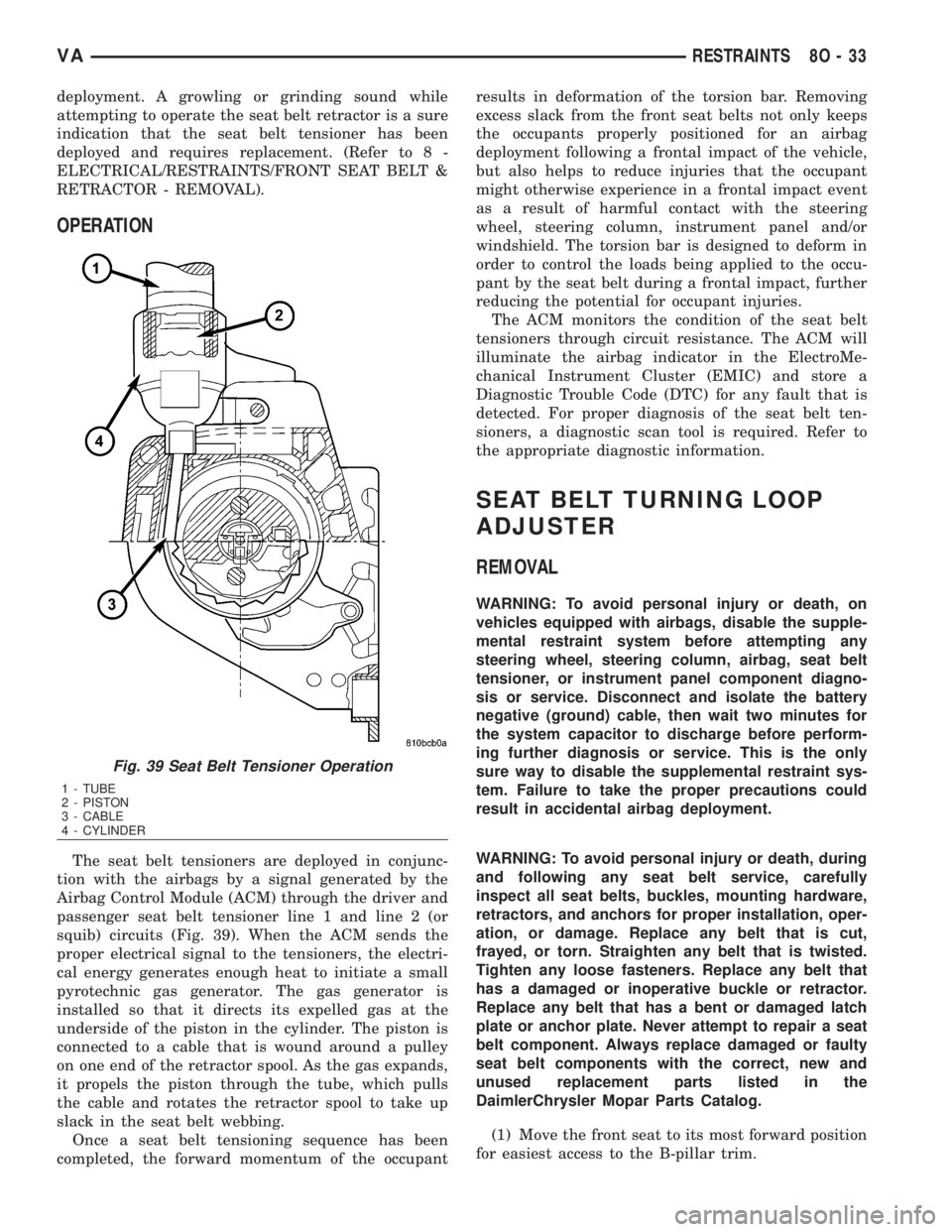
The seat belt tensioners are deployed in conjunc-
tion with the airbags by a signal generated by the
Airbag Control Module (ACM) through the driver and
passenger seat belt tensioner line 1 and line 2 (or
squib) circuits (Fig. 39). When the ACM sends the
proper electrical signal to the tensioners, the electri-
cal energy generates enough heat to initiate a small
pyrotechnic gas generator. The gas generator is
installed so that it directs its expelled gas at the
underside of the piston in the cylinder. The piston is
connected to a cable that is wound around a pulley
on one end of the retractor spool. As the gas expands,
it propels the piston through the tube, which pulls
the cable and rotates the retractor spool to take up
slack in the seat belt webbing.
Once a seat belt tensioning sequence has been
completed, the forward momentum of the occupantresults in deformation of the torsion bar. Removing
excess slack from the front seat belts not only keeps
the occupants properly positioned for an airbag
deployment following a frontal impact of the vehicle,
but also helps to reduce injuries that the occupant
might otherwise experience in a frontal impact event
as a result of harmful contact with the steering
wheel, steering column, instrument panel and/or
windshield. The torsion bar is designed to deform in
order to control the loads being applied to the occu-
pant by the seat belt during a frontal impact, further
reducing the potential for occupant injuries.
The ACM monitors the condition of the seat belt
tensioners through circuit resistance. The ACM will
illuminate the airbag indicator in the ElectroMe-
chanical Instrument Cluster (EMIC) and store a
Diagnostic Trouble Code (DTC) for any fault that is
detected. For proper diagnosis of the seat belt ten-
sioners, a diagnostic scan tool is required. Refer to
the appropriate diagnostic information.
SEAT BELT TURNING LOOP
ADJUSTER
REMOVAL
WARNING: To avoid personal injury or death, on
vehicles equipped with airbags, disable the supple-
mental restraint system before attempting any
steering wheel, steering column, airbag, seat belt
tensioner, or instrument panel component diagno-
sis or service. Disconnect and isolate the battery
negative (ground) cable, then wait two minutes for
the system capacitor to discharge before perform-
ing further diagnosis or service. This is the only
sure way to disable the supplemental restraint sys-
tem. Failure to take the proper precautions could
result in accidental airbag deployment.
WARNING: To avoid personal injury or death, during
and following any seat belt service, carefully
inspect all seat belts, buckles, mounting hardware,
retractors, and anchors for proper installation, oper-
ation, or damage. Replace any belt that is cut,
frayed, or torn. Straighten any belt that is twisted.
Tighten any loose fasteners. Replace any belt that
has a damaged or inoperative buckle or retractor.
Replace any belt that has a bent or damaged latch
plate or anchor plate. Never attempt to repair a seat
belt component. Always replace damaged or faulty
seat belt components with the correct, new and
unused replacement parts listed in the
DaimlerChrysler Mopar Parts Catalog.
(1) Move the front seat to its most forward position
for easiest access to the B-pillar trim.
Fig. 39 Seat Belt Tensioner Operation
1 - TUBE
2 - PISTON
3 - CABLE
4 - CYLINDER
VARESTRAINTS 8O - 33
Page 1030 of 2305
(9) Reinstall the grab handle onto the headliner.
(Refer to 23 - BODY/INTERIOR/ASSIST HANDLE -
INSTALLATION).
(10) Reinstall the trim onto the inside of the B-pil-
lar. (Refer to 23 - BODY/INTERIOR/B-PILLAR TRIM
- INSTALLATION).
(11) Reinstall the pinch welt to the front door
opening (Fig. 44).
(12) Do not reconnect the battery negative cable at
this time. The supplemental restraint system verifi-
cation test procedure should be performed following
service of any supplemental restraint system compo-
nent. (Refer to 8 - ELECTRICAL/RESTRAINTS -
STANDARD PROCEDURE - VERIFICATION TEST).
SIDE IMPACT SENSOR
DESCRIPTION
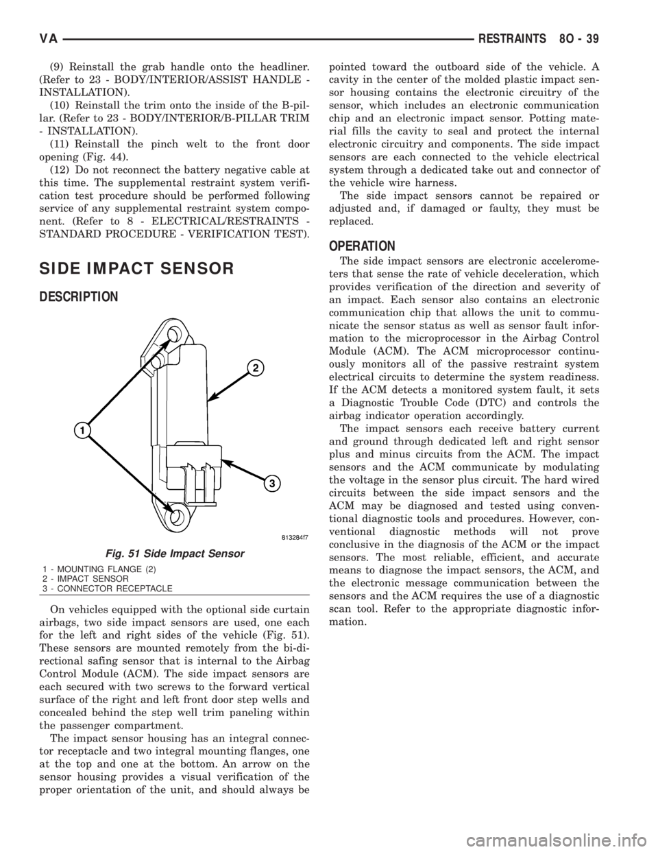
On vehicles equipped with the optional side curtain
airbags, two side impact sensors are used, one each
for the left and right sides of the vehicle (Fig. 51).
These sensors are mounted remotely from the bi-di-
rectional safing sensor that is internal to the Airbag
Control Module (ACM). The side impact sensors are
each secured with two screws to the forward vertical
surface of the right and left front door step wells and
concealed behind the step well trim paneling within
the passenger compartment.
The impact sensor housing has an integral connec-
tor receptacle and two integral mounting flanges, one
at the top and one at the bottom. An arrow on the
sensor housing provides a visual verification of the
proper orientation of the unit, and should always bepointed toward the outboard side of the vehicle. A
cavity in the center of the molded plastic impact sen-
sor housing contains the electronic circuitry of the
sensor, which includes an electronic communication
chip and an electronic impact sensor. Potting mate-
rial fills the cavity to seal and protect the internal
electronic circuitry and components. The side impact
sensors are each connected to the vehicle electrical
system through a dedicated take out and connector of
the vehicle wire harness.
The side impact sensors cannot be repaired or
adjusted and, if damaged or faulty, they must be
replaced.
OPERATION
The side impact sensors are electronic accelerome-
ters that sense the rate of vehicle deceleration, which
provides verification of the direction and severity of
an impact. Each sensor also contains an electronic
communication chip that allows the unit to commu-
nicate the sensor status as well as sensor fault infor-
mation to the microprocessor in the Airbag Control
Module (ACM). The ACM microprocessor continu-
ously monitors all of the passive restraint system
electrical circuits to determine the system readiness.
If the ACM detects a monitored system fault, it sets
a Diagnostic Trouble Code (DTC) and controls the
airbag indicator operation accordingly.
The impact sensors each receive battery current
and ground through dedicated left and right sensor
plus and minus circuits from the ACM. The impact
sensors and the ACM communicate by modulating
the voltage in the sensor plus circuit. The hard wired
circuits between the side impact sensors and the
ACM may be diagnosed and tested using conven-
tional diagnostic tools and procedures. However, con-
ventional diagnostic methods will not prove
conclusive in the diagnosis of the ACM or the impact
sensors. The most reliable, efficient, and accurate
means to diagnose the impact sensors, the ACM, and
the electronic message communication between the
sensors and the ACM requires the use of a diagnostic
scan tool. Refer to the appropriate diagnostic infor-
mation.
Fig. 51 Side Impact Sensor
1 - MOUNTING FLANGE (2)
2 - IMPACT SENSOR
3 - CONNECTOR RECEPTACLE
VARESTRAINTS 8O - 39
Page 1683 of 2305
If a high-pressure line connection is leaking, coun-
terhold and tighten the connection to specification
then perform this procedure again (Refer to 14 -
FUEL SYSTEM - STANDARD PROCEDURE).
Replace any damaged, restricted or leaking high-
pressure fuel lines with the correct replacement
line.
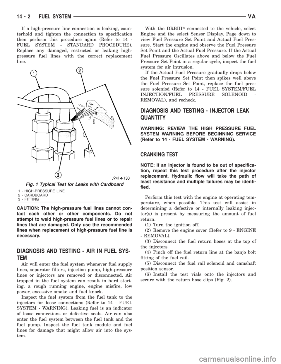
CAUTION: The high-pressure fuel lines cannot con-
tact each other or other components. Do not
attempt to weld high-pressure fuel lines or to repair
lines that are damaged. Only use the recommended
lines when replacement of high-pressure fuel line is
necessary.
DIAGNOSIS AND TESTING - AIR IN FUEL SYS-
TEM
Air will enter the fuel system whenever fuel supply
lines, separator filters, injection pump, high-pressure
lines or injectors are removed or disconnected. Air
trapped in the fuel system can result in hard start-
ing, a rough running engine, engine misfire, low
power, excessive smoke and fuel knock.
Inspect the fuel system from the fuel tank to the
injectors for loose connections (Refer to 14 - FUEL
SYSTEM - WARNING). Leaking fuel is an indicator
of loose connections or defective seals. Air can also
enter the fuel system between the fuel tank and the
fuel pump. Inspect the fuel tank module and fuel
lines for damage that might allow air into the sys-
tem.With the DRBIIItconnected to the vehicle, select
Engine and the select Sensor Display. Page down to
view Fuel Pressure Set Point and Actual Fuel Pres-
sure. Start the engine and observe the Fuel Pressure
Set Point and the Actual Fuel Pressure. If the Actual
Fuel Pressure Oscillates above and below the Fuel
Pressure Set Point in a regular cycle, inspect the fuel
system for air intrusion.
If the Actual Fuel Pressure gradually drops below
the Fuel Pressure Set Point then spikes well above
the Fuel Pressure Set Point, replace the fuel pres-
sure soleniod (Refer to 14 - FUEL SYSTEM/FUEL
INJECTION/FUEL PRESSURE SOLENOID -
REMOVAL), and recheck.
DIAGNOSIS AND TESTING - INJECTOR LEAK
QUANTITY
WARNING: REVIEW THE HIGH PRESSURE FUEL
SYSTEM WARNING BEFORE BEGINNING SERVICE
(Refer to 14 - FUEL SYSTEM - WARNING).
CRANKING TEST
NOTE: If an injector is found to be out of specifica-
tion, repeat this test procedure after the injector
replacement. Hydraulic flow will take the path of
least resistance and multiple failures may be identi-
fied.
Perform this test with the engine at operating tem-
perature, when possible. This test will assist in
determining a defective or internally leaking injec-
tor(s) is present by measuring the amount of fuel
return.
(1) Turn the ignition off.
(2) Remove the engine cover (Refer to 9 - ENGINE
- REMOVAL).
(3) Disconnect the fuel return hoses at the top of
the injectors.
(4) Pinch off the fuel return line at the banjo bolt
fitting of the fuel rail.
(5) Disconnect the fuel rail solenoid and camshaft
position sensor.
(6) Install the test vials onto the injectors and
secure with the return hose clips (Fig. 2).
Fig. 1 Typical Test for Leaks with Cardboard
1 - HIGH-PRESSURE LINE
2 - CARDBOARD
3 - FITTING
14 - 2 FUEL SYSTEMVA
Page 1790 of 2305
(a) Attach Adapter 8266-18 (2) to Handle 8266-8
(1).
(b) Attach dial indicator C-3339 (3) to Handle
8266-8 (1).
(c) Install the assembled tool onto the input
shaft of the transmission and tighten the retaining
screw on Adapter 8266-18 (2) to secure it to the
input shaft.
(d) Position the dial indicator plunger against a
flat spot on the oil pump and zero the dial indica-
tor.
(e) Move the input shaft in and out. Record the
maximum travel for assembly reference.
(4) Loosen guide bushing (12) (Fig. 40) and remove
from transmission housing.
(5) Detach oil pan (5) (Fig. 40).
(6) Remove oil filter (4) (Fig. 40).
(7) Unscrew Torx socket bolts (3) and remove elec-
trohydraulic unit (2).(8) Place the transmission in PARK to prepare for
the removal of the output shaft nut.
(9) Remove the nut holding the propeller shaft
flange to the output shaft and remove the flange.
(10) Remove the transmission rear oil seal with a
suitable slide hammer and screw.
(11) Remove the transmission output shaft washer.
Be sure to tag the washer since it is very similar to
the geartrain end-play shim and they must not be
interchanged.
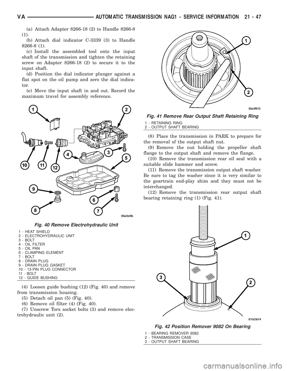
(12) Remove the transmission rear output shaft
bearing retaining ring (1) (Fig. 41).
Fig. 40 Remove Electrohydraulic Unit
1 - HEAT SHIELD
2 - ELECTROHYDRAULIC UNIT
3 - BOLT
4 - OIL FILTER
5 - OIL PAN
6 - CLAMPING ELEMENT
7 - BOLT
8 - DRAIN PLUG
9 - DRAIN PLUG GASKET
10 - 13-PIN PLUG CONNECTOR
11 - BOLT
12 - GUIDE BUSHING
Fig. 41 Remove Rear Output Shaft Retaining Ring
1 - RETAINING RING
2 - OUTPUT SHAFT BEARING
Fig. 42 Position Remover 9082 On Bearing
1 - BEARING REMOVER 9082
2 - TRANSMISSION CASE
3 - OUTPUT SHAFT BEARING
VAAUTOMATIC TRANSMISSION NAG1 - SERVICE INFORMATION 21 - 47
Page 1801 of 2305
installed. Retaining rings are available in thick-
nesses of 2.0 mm (0.079 in.), 2.1 mm (0.083 in.), and
2.2 mm (0.087 in.).
(31) Rotate the transmission so that the bellhous-
ing is pointed upward and ensuring that the output
shaft is allowed to move freely.
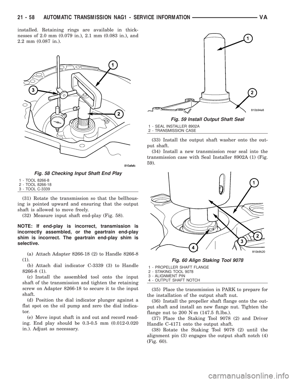
(32) Measure input shaft end-play (Fig. 58).
NOTE: If end-play is incorrect, transmission is
incorrectly assembled, or the geartrain end-play
shim is incorrect. The geartrain end-play shim is
selective.
(a) Attach Adapter 8266-18 (2) to Handle 8266-8
(1).
(b) Attach dial indicator C-3339 (3) to Handle
8266-8 (1).
(c) Install the assembled tool onto the input
shaft of the transmission and tighten the retaining
screw on Adapter 8266-18 to secure it to the input
shaft.
(d) Position the dial indicator plunger against a
flat spot on the oil pump and zero the dial indica-
tor.
(e) Move input shaft in and out and record read-
ing. End play should be 0.3-0.5 mm (0.012-0.020
in.). Adjust as necessary.(33) Install the output shaft washer onto the out-
put shaft.
(34) Install a new transmission rear seal into the
transmission case with Seal Installer 8902A (1) (Fig.
59).
(35) Place the transmission in PARK to prepare for
the installation of the output shaft nut.
(36) Install the propeller shaft flange onto the out-
put shaft and install an new flange nut. Tighten the
flange nut to 200 N´m (147.5 ft.lbs.).
(37) Place the Staking Tool 9078 (2) and Driver
Handle C-4171 onto the output shaft.
(38) Rotate the Staking Tool 9078 (2) until the
alignment pin (3) engages the output shaft notch (4)
(Fig. 60).
Fig. 58 Checking Input Shaft End Play
1 - TOOL 8266-8
2 - TOOL 8266-18
3 - TOOL C-3339
Fig. 59 Install Output Shaft Seal
1 - SEAL INSTALLER 8902A
2 - TRANSMISSION CASE
Fig. 60 Align Staking Tool 9078
1 - PROPELLER SHAFT FLANGE
2 - STAKING TOOL 9078
3 - ALIGNMENT PIN
4 - OUTPUT SHAFT NOTCH
21 - 58 AUTOMATIC TRANSMISSION NAG1 - SERVICE INFORMATIONVA
Page 1830 of 2305
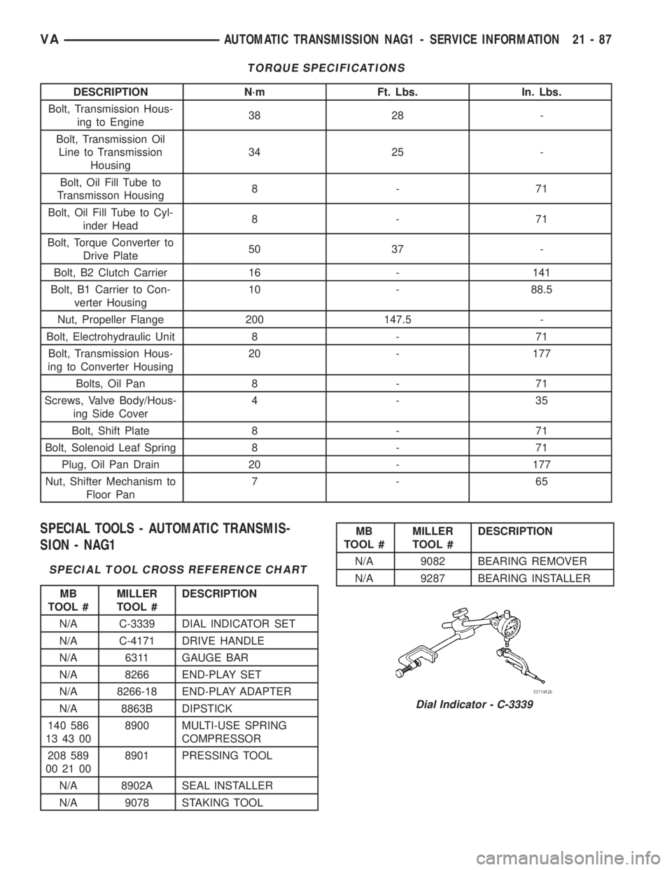
TORQUE SPECIFICATIONS
DESCRIPTION N´m Ft. Lbs. In. Lbs.
Bolt, Transmission Hous-
ing to Engine38 28 -
Bolt, Transmission Oil
Line to Transmission
Housing34 25 -
Bolt, Oil Fill Tube to
Transmisson Housing8-71
Bolt, Oil Fill Tube to Cyl-
inder Head8-71
Bolt, Torque Converter to
Drive Plate50 37 -
Bolt, B2 Clutch Carrier 16 - 141
Bolt, B1 Carrier to Con-
verter Housing10 - 88.5
Nut, Propeller Flange 200 147.5 -
Bolt, Electrohydraulic Unit 8 - 71
Bolt, Transmission Hous-
ing to Converter Housing20 - 177
Bolts, Oil Pan 8 - 71
Screws, Valve Body/Hous-
ing Side Cover4-35
Bolt, Shift Plate 8 - 71
Bolt, Solenoid Leaf Spring 8 - 71
Plug, Oil Pan Drain 20 - 177
Nut, Shifter Mechanism to
Floor Pan7-65
SPECIAL TOOLS - AUTOMATIC TRANSMIS-
SION - NAG1
SPECIAL TOOL CROSS REFERENCE CHART
MB
TOOL #MILLER
TOOL #DESCRIPTION
N/A C-3339 DIAL INDICATOR SET
N/A C-4171 DRIVE HANDLE
N/A 6311 GAUGE BAR
N/A 8266 END-PLAY SET
N/A 8266-18 END-PLAY ADAPTER
N/A 8863B DIPSTICK
140 586
13 43 008900 MULTI-USE SPRING
COMPRESSOR
208 589
00 21 008901 PRESSING TOOL
N/A 8902A SEAL INSTALLER
N/A 9078 STAKING TOOL
MB
TOOL #MILLER
TOOL #DESCRIPTION
N/A 9082 BEARING REMOVER
N/A 9287 BEARING INSTALLER
Dial Indicator - C-3339
VAAUTOMATIC TRANSMISSION NAG1 - SERVICE INFORMATION 21 - 87
Page 1929 of 2305
Radial runout of more than 1.5 mm (.060 inch)
measured at the center line of the tread may cause
the vehicle to shake.
Lateral runout of more than 2.0 mm (.080 inch)
measured near the shoulder of the tire may cause the
vehicle to shake.
Sometimes radial runout can be reduced. Relocate
the wheel and tire assembly on the mounting studs
(See Method 1). If this does not reduce runout to an
acceptable level, the tire can be rotated on the wheel.
(See Method 2).
METHOD 1 (RELOCATE WHEEL ON HUB)
(1) Drive vehicle a short distance to eliminate tire
flat spotting from a parked position.
(2) Check wheel bearings and adjust if adjustable
or replace if necessary.
(3) Check the wheel mounting surface.
(4) Relocate wheel on the mounting, two studs
over from the original position.
(5) Tighten wheel nuts until all are properly
torqued, to eliminate brake distortion.
(6) Check radial runout. If still excessive, mark
tire sidewall, wheel, and stud at point of maximum
runout and proceed to Method 2.
METHOD 2 (RELOCATE TIRE ON WHEEL)
NOTE: Rotating the tire on wheel is particularly
effective when there is runout in both tire and
wheel.
(1) Remove tire from wheel and mount wheel on
service dynamic balance machine.
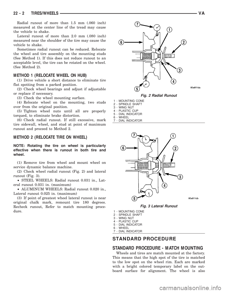
(2) Check wheel radial runout (Fig. 2) and lateral
runout (Fig. 3).
²STEEL WHEELS: Radial runout 0.031 in., Lat-
eral runout 0.031 in. (maximum)
²ALUMINUM WHEELS: Radial runout 0.020 in.,
Lateral runout 0.025 in. (maximum)
(3) If point of greatest wheel lateral runout is near
original chalk mark, remount tire 180 degrees.
Recheck runout, Refer to match mounting proce-
dure.
STANDARD PROCEDURE
STANDARD PROCEDURE - MATCH MOUNTING
Wheels and tires are match mounted at the factory.
This means that the high spot of the tire is matched
to the low spot on the wheel rim. Each are marked
with a bright colored temporary label on the out-
board surface for alignment. The wheel is also
Fig. 2 Radial Runout
1 - MOUNTING CONE
2 - SPINDLE SHAFT
3 - WING NUT
4 - PLASTIC CUP
5 - DIAL INDICATOR
6 - WHEEL
7 - DIAL INDICATOR
Fig. 3 Lateral Runout
1 - MOUNTING CONE
2 - SPINDLE SHAFT
3 - WING NUT
4 - PLASTIC CUP
5 - DIAL INDICATOR
6 - WHEEL
7 - DIAL INDICATOR
22 - 2 TIRES/WHEELSVA