2006 MERCEDES-BENZ SPRINTER lock
[x] Cancel search: lockPage 811 of 2305
INSTALLATION
INSTALLATION - FRONT (SRW)
(1) Install the disc brake rotor to the hub and
install two lug studs to hold rotor in place.
(2) Install the locking bolt for the rotor (Fig. 24).
Tighten to 23 N´m (204 in. lbs.).
(3) Install the disc brake caliper adapter (Fig. 24).
Tighten to 170 N´m (125 ft. lbs.) (Refer to 5 -
BRAKES/HYDRAULIC/MECHANICAL/DISC
BRAKE CALIPER ADAPTER - INSTALLATION).
(4) Install the brake pads (Refer to 5 - BRAKES/
HYDRAULIC/MECHANICAL/BRAKE PADS/SHOES
- INSTALLATION) (Fig. 24).
(5) Press and release the brake pedal several times
until pressure has built up.
(6) Check fluid in reservoir and correct if neces-
sary.
(7) Install the front wheels (Refer to 22 - TIRES/
WHEELS/WHEELS - INSTALLATION).
(8) Lower the vehicle.
INSTALLATION - REAR (SRW)
(1) Install the disc brake rotor to the hub and
install two lug studs to hold rotor in place (Fig. 25).
(2) Apply the parking brake.
(3) Install the locking bolt for the rotor (Fig. 25).
Tighten to 23 N´m (204 in. lbs.).
(4) Install the disc brake caliper adapter (Fig. 25).
Tighten to 90 N´m (66 ft. lbs.) (Refer to 5 - BRAKES/HYDRAULIC/MECHANICAL/DISC BRAKE CALI-
PER ADAPTER - INSTALLATION).
(5) Install the brake pads (Refer to 5 - BRAKES/
HYDRAULIC/MECHANICAL/BRAKE PADS/SHOES
- INSTALLATION) (Fig. 25).
(6) Release the parking brake.
(7) Adjust the parking brake (Refer to 5 -
BRAKES/PARKING BRAKE/SHOES - ADJUST-
MENTS).
(8) Press and release the brake pedal several times
until pressure has built up.
(9) Check fluid in reservoir and correct if neces-
sary.
(10) Install the rear wheels.
(11) Lower the vehicle.
INSTALLATION - FRONT (DRW)
(1) Install the disc brake rotor to the hub and
install two lug studs to hold rotor in place.
(2) Install the locking bolt for the rotor (Fig. 26).
Tighten to 23 N´m (204 in. lbs.).
(3) Install the disc brake caliper adapter (Fig. 26).
Tighten to 170 N´m (125 ft. lbs.) (Refer to 5 -
BRAKES/HYDRAULIC/MECHANICAL/DISC
BRAKE CALIPER ADAPTER - INSTALLATION).
(4) Install the wheel flange ring. Tighten to 180
N´m (133 ft. lbs.)
(5) Install the brake pads (Refer to 5 - BRAKES/
HYDRAULIC/MECHANICAL/BRAKE PADS/SHOES
- INSTALLATION) (Fig. 26).
(6) Press and release the brake pedal several times
until pressure has built up.
(7) Check fluid in reservoir and correct if neces-
sary.
(8) Install the front wheels (Refer to 22 - TIRES/
WHEELS/WHEELS - INSTALLATION).
(9) Lower the vehicle.
INSTALLATION - REAR (DRW)
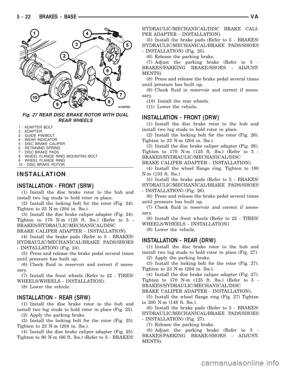
(1) Install the disc brake rotor to the hub and
install two lug studs to hold rotor in place (Fig. 27).
(2) Apply the parking brake.
(3) Install the locking bolt for the rotor (Fig. 27).
Tighten to 23 N´m (204 in. lbs.).
(4) Install the disc brake caliper adapter (Fig. 27).
Tighten to 170 N´m (125 ft. lbs.) (Refer to 5 -
BRAKES/HYDRAULIC/MECHANICAL/DISC
BRAKE CALIPER ADAPTER - INSTALLATION).
(5) Install the wheel flange ring (Fig. 27) Tighten
to 200 N´m (148 ft. lbs.).
(6) Install the brake pads (Refer to 5 - BRAKES/
HYDRAULIC/MECHANICAL/BRAKE PADS/SHOES
- INSTALLATION) (Fig. 27).
(7) Release the parking brake.
(8) Adjust the parking brake (Refer to 5 -
BRAKES/PARKING BRAKE/SHOES - ADJUST-
MENTS).
Fig. 27 REAR DISC BRAKE ROTOR WITH DUAL
REAR WHEELS
1 - ADAPTER BOLT
2 - ADAPTER
3 - GUIDE PIN/BOLT
4 - WEAR INDICATOR
5 - DISC BRAKE CALIPER
6 - RETAINING SPRING
7 - DISC BRAKE PADS
8 - WHEEL FLANGE RING MOUNITNG BOLT
9 - WHEEL FLANGE RING
10 - DISC BRAKE ROTOR
5 - 22 BRAKES - BASEVA
Page 813 of 2305
SPECIAL TOOLS
PARK BRAKE
SPECIAL TOOL CROSS REFERENCE CHART
MB
TOOL #MILLER
TOOL #DESCRIPTION
116 589
01 62 009280 RETURN SPRING PULL-
ING HOOK
112 589
09 61 009281 RETAINING SPRING
TOOL
901 589
00 63 009289 RETAINING CLIP RE-
LEASE TOOL
CABLE TENSIONER
REMOVAL
NOTE: Observe the installation position of the
brake control cable lock, for a reference on instal-
lation.
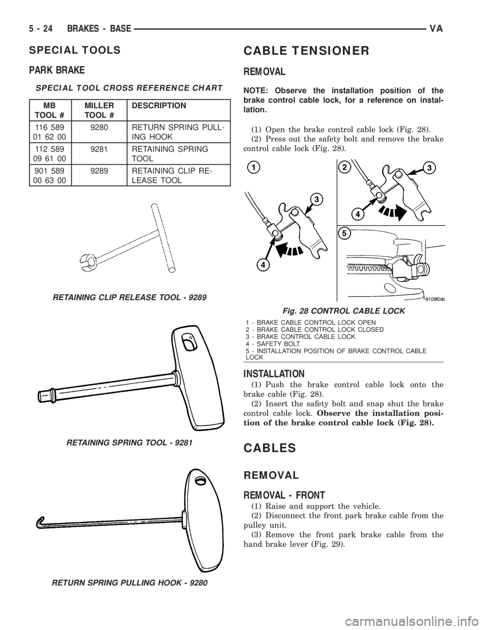
(1) Open the brake control cable lock (Fig. 28).
(2) Press out the safety bolt and remove the brake
control cable lock (Fig. 28).
INSTALLATION
(1) Push the brake control cable lock onto the
brake cable (Fig. 28).
(2) Insert the safety bolt and snap shut the brake
control cable lock.Observe the installation posi-
tion of the brake control cable lock (Fig. 28).
CABLES
REMOVAL
REMOVAL - FRONT
(1) Raise and support the vehicle.
(2) Disconnect the front park brake cable from the
pulley unit.
(3) Remove the front park brake cable from the
hand brake lever (Fig. 29).
RETAINING CLIP RELEASE TOOL - 9289
RETAINING SPRING TOOL - 9281
RETURN SPRING PULLING HOOK - 9280
Fig. 28 CONTROL CABLE LOCK
1 - BRAKE CABLE CONTROL LOCK OPEN
2 - BRAKE CABLE CONTROL LOCK CLOSED
3 - BRAKE CONTROL CABLE LOCK
4 - SAFETY BOLT
5 - INSTALLATION POSITION OF BRAKE CONTROL CABLE
LOCK
5 - 24 BRAKES - BASEVA
Page 814 of 2305
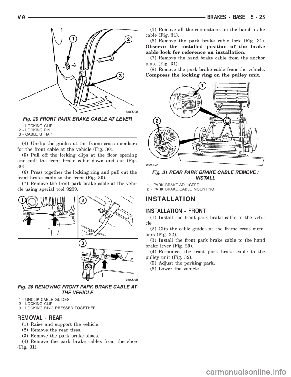
(4) Unclip the guides at the frame cross members
for the front cable at the vehicle (Fig. 30).
(5) Pull off the locking clips at the floor opening
and pull the front brake cable down and out (Fig.
30).
(6) Press together the locking ring and pull out the
front brake cable to the front (Fig. 30).
(7) Remove the front park brake cable at the vehi-
cle using special tool 9289.
REMOVAL - REAR
(1) Raise and support the vehicle.
(2) Remove the rear tires.
(3) Remove the park brake shoes.
(4) Remove the park brake cables from the shoe
(Fig. 31).(5) Remove all the connections on the hand brake
cable (Fig. 31).
(6) Remove the park brake cable lock (Fig. 31).
Observe the installed position of the brake
cable lock for reference on installation.
(7) Remove the hand brake cable from the anchor
plate (Fig. 31).
(8) Remove the park brake cable from the vehicle.
Compress the locking ring on the pulley unit.
INSTALLATION
INSTALLATION - FRONT
(1) Install the front park brake cable to the vehi-
cle.
(2) Clip the cable guides at the frame cross mem-
bers (Fig. 32).
(3) Install the front park brake cable to the hand
brake lever (Fig. 29).
(4) Reconnect the front park brake cable to the
pulley unit (Fig. 32).
(5) Adjust the parking park.
(6) Lower the vehicle.
Fig. 29 FRONT PARK BRAKE CABLE AT LEVER
1 - LOCKING CLIP
2 - LOCKING PIN
3 - CABLE STRAP
Fig. 30 REMOVING FRONT PARK BRAKE CABLE AT
THE VEHICLE
1 - UNCLIP CABLE GUIDES
2 - LOCKING CLIP
3 - LOCKING RING PRESSED TOGETHER
Fig. 31 REAR PARK BRAKE CABLE REMOVE /
INSTALL
1 - PARK BRAKE ADJUSTER
2 - PARK BRAKE CABLE MOUNTING
VABRAKES - BASE 5 - 25
Page 815 of 2305
INSTALLATION - REAR
NOTE: Route the park brake cable free of tension
and the risk of chafing.
(1) Install the hand brake cable to the anchor
plate (Fig. 31).
(2) Install the park brake cable lock (Fig. 31).
(3) Install all connections on the hardware cable
(Fig. 31).
(4) Install the park brake cables to the shoe (Fig.
31).
(5) Install the park brake shoes.
(6) Install the rear wheels.
(7) Adjust the park brakes.
(8) Lower the vehicle.
ADJUSTMENTS
ADJUSTMENT - PARKING BRAKE CABLES
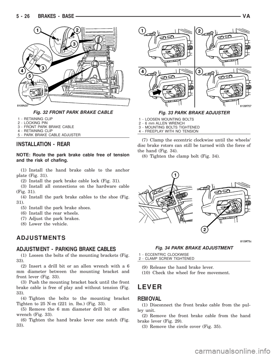
(1) Loosen the bolts of the mounting brackets (Fig.
33).
(2) Insert a drill bit or an allen wrench with a 6
mm diameter between the mounting bracket and
front lever (Fig. 33).
(3) Push the mounting bracket back until the front
brake cable is free of play and without tension (Fig.
33).
(4) Tighten the bolts to the mounting bracket
Tighten to 25 N´m (221 in. lbs.) (Fig. 33).
(5) Remove the 6 mm diameter drill bit or allen
wrench (Fig. 33).
(6) Tighten the hand brake lever one notch (Fig.
33).(7) Clamp the eccentric clockwise until the wheels/
disc brake rotors can still be turned with the force of
the hand (Fig. 34).
(8) Tighten the clamp bolt (Fig. 34).
(9) Release the hand brake lever.
(10) Check the wheel for free movement.
LEVER
REMOVAL
(1) Disconnect the front brake cable from the pul-
ley unit.
(2) Remove the front brake cable from the hand
brake lever (Fig. 29).
(3) Remove the circle cover (Fig. 35).
Fig. 32 FRONT PARK BRAKE CABLE
1 - RETAINING CLIP
2 - LOCKING PIN
3 - FRONT PARK BRAKE CABLE
4 - RETAINING CLIP
5 - PARK BRAKE CABLE ADJUSTER
Fig. 33 PARK BRAKE ADJUSTER
1 - LOOSEN MOUNTING BOLTS
2-6mmALLEN WRENCH
3 - MOUNTING BOLTS TIGHTENED
4 - FREEPLAY WITH NO TENSION
Fig. 34 PARK BRAKE ADJUSTMENT
1 - ECCENTRIC CLOCKWISE
2 - CLAMP SCREW TIGHTENED
5 - 26 BRAKES - BASEVA
Page 816 of 2305
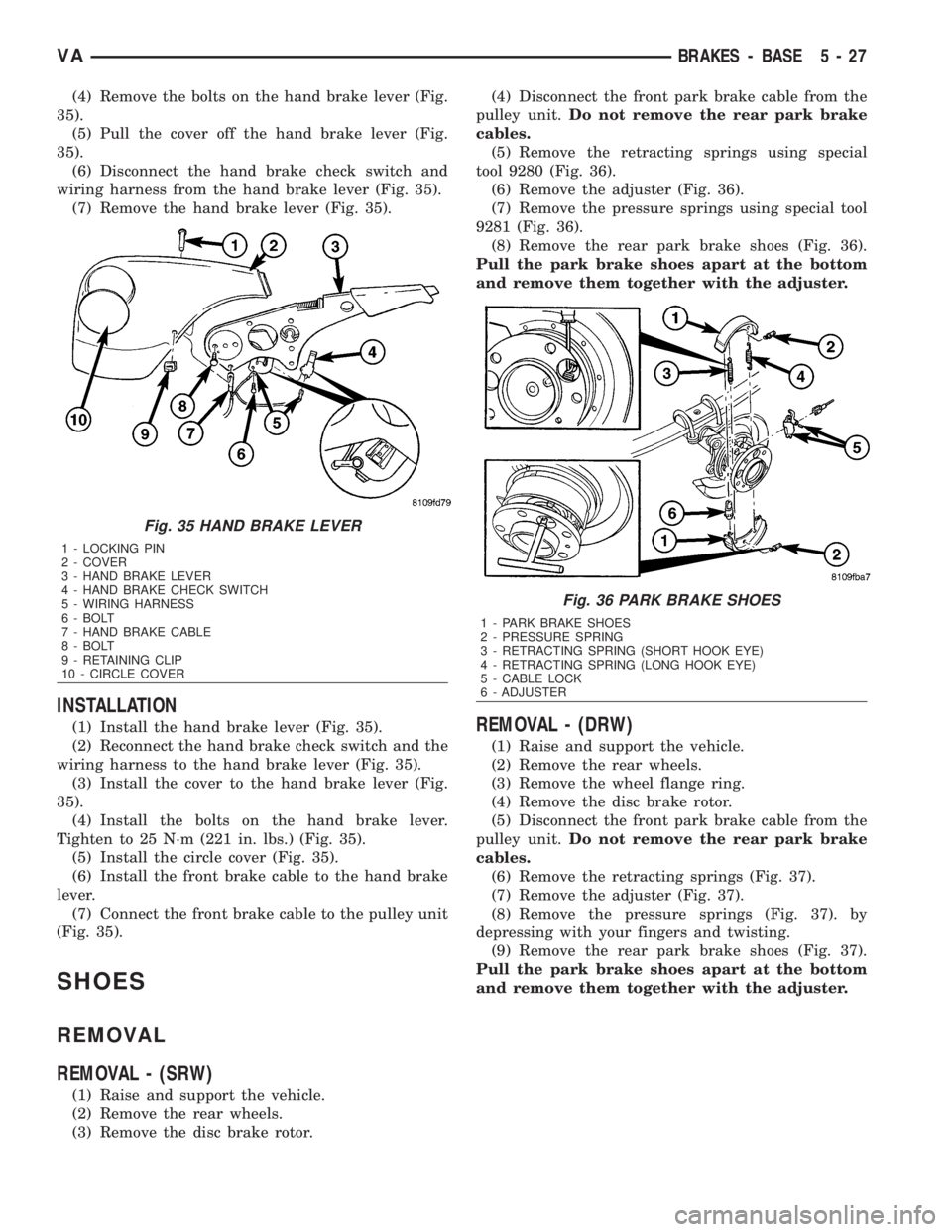
(4) Remove the bolts on the hand brake lever (Fig.
35).
(5) Pull the cover off the hand brake lever (Fig.
35).
(6) Disconnect the hand brake check switch and
wiring harness from the hand brake lever (Fig. 35).
(7) Remove the hand brake lever (Fig. 35).
INSTALLATION
(1) Install the hand brake lever (Fig. 35).
(2) Reconnect the hand brake check switch and the
wiring harness to the hand brake lever (Fig. 35).
(3) Install the cover to the hand brake lever (Fig.
35).
(4) Install the bolts on the hand brake lever.
Tighten to 25 N´m (221 in. lbs.) (Fig. 35).
(5) Install the circle cover (Fig. 35).
(6) Install the front brake cable to the hand brake
lever.
(7) Connect the front brake cable to the pulley unit
(Fig. 35).
SHOES
REMOVAL
REMOVAL - (SRW)
(1) Raise and support the vehicle.
(2) Remove the rear wheels.
(3) Remove the disc brake rotor.(4) Disconnect the front park brake cable from the
pulley unit.Do not remove the rear park brake
cables.
(5) Remove the retracting springs using special
tool 9280 (Fig. 36).
(6) Remove the adjuster (Fig. 36).
(7) Remove the pressure springs using special tool
9281 (Fig. 36).
(8) Remove the rear park brake shoes (Fig. 36).
Pull the park brake shoes apart at the bottom
and remove them together with the adjuster.
REMOVAL - (DRW)
(1) Raise and support the vehicle.
(2) Remove the rear wheels.
(3) Remove the wheel flange ring.
(4) Remove the disc brake rotor.
(5) Disconnect the front park brake cable from the
pulley unit.Do not remove the rear park brake
cables.
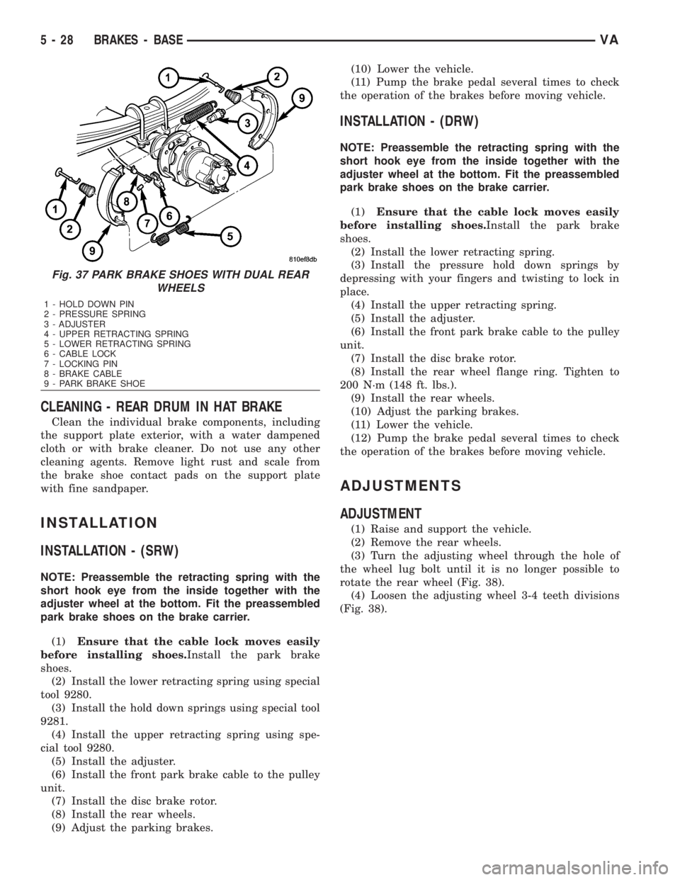
(6) Remove the retracting springs (Fig. 37).
(7) Remove the adjuster (Fig. 37).
(8) Remove the pressure springs (Fig. 37). by
depressing with your fingers and twisting.
(9) Remove the rear park brake shoes (Fig. 37).
Pull the park brake shoes apart at the bottom
and remove them together with the adjuster.
Fig. 35 HAND BRAKE LEVER
1 - LOCKING PIN
2 - COVER
3 - HAND BRAKE LEVER
4 - HAND BRAKE CHECK SWITCH
5 - WIRING HARNESS
6 - BOLT
7 - HAND BRAKE CABLE
8 - BOLT
9 - RETAINING CLIP
10 - CIRCLE COVER
Fig. 36 PARK BRAKE SHOES
1 - PARK BRAKE SHOES
2 - PRESSURE SPRING
3 - RETRACTING SPRING (SHORT HOOK EYE)
4 - RETRACTING SPRING (LONG HOOK EYE)
5 - CABLE LOCK
6 - ADJUSTER
VABRAKES - BASE 5 - 27
Page 817 of 2305
CLEANING - REAR DRUM IN HAT BRAKE
Clean the individual brake components, including
the support plate exterior, with a water dampened
cloth or with brake cleaner. Do not use any other
cleaning agents. Remove light rust and scale from
the brake shoe contact pads on the support plate
with fine sandpaper.
INSTALLATION
INSTALLATION - (SRW)
NOTE: Preassemble the retracting spring with the
short hook eye from the inside together with the
adjuster wheel at the bottom. Fit the preassembled
park brake shoes on the brake carrier.
(1)Ensure that the cable lock moves easily
before installing shoes.Install the park brake
shoes.
(2) Install the lower retracting spring using special
tool 9280.
(3) Install the hold down springs using special tool
9281.
(4) Install the upper retracting spring using spe-
cial tool 9280.
(5) Install the adjuster.
(6) Install the front park brake cable to the pulley
unit.
(7) Install the disc brake rotor.
(8) Install the rear wheels.
(9) Adjust the parking brakes.(10) Lower the vehicle.
(11) Pump the brake pedal several times to check
the operation of the brakes before moving vehicle.
INSTALLATION - (DRW)
NOTE: Preassemble the retracting spring with the
short hook eye from the inside together with the
adjuster wheel at the bottom. Fit the preassembled
park brake shoes on the brake carrier.
(1)Ensure that the cable lock moves easily
before installing shoes.Install the park brake
shoes.
(2) Install the lower retracting spring.
(3) Install the pressure hold down springs by
depressing with your fingers and twisting to lock in
place.
(4) Install the upper retracting spring.
(5) Install the adjuster.
(6) Install the front park brake cable to the pulley
unit.
(7) Install the disc brake rotor.
(8) Install the rear wheel flange ring. Tighten to
200 N´m (148 ft. lbs.).
(9) Install the rear wheels.
(10) Adjust the parking brakes.
(11) Lower the vehicle.
(12) Pump the brake pedal several times to check
the operation of the brakes before moving vehicle.
ADJUSTMENTS
ADJUSTMENT
(1) Raise and support the vehicle.
(2) Remove the rear wheels.
(3) Turn the adjusting wheel through the hole of
the wheel lug bolt until it is no longer possible to
rotate the rear wheel (Fig. 38).
(4) Loosen the adjusting wheel 3-4 teeth divisions
(Fig. 38).
Fig. 37 PARK BRAKE SHOES WITH DUAL REAR
WHEELS
1 - HOLD DOWN PIN
2 - PRESSURE SPRING
3 - ADJUSTER
4 - UPPER RETRACTING SPRING
5 - LOWER RETRACTING SPRING
6 - CABLE LOCK
7 - LOCKING PIN
8 - BRAKE CABLE
9 - PARK BRAKE SHOE
5 - 28 BRAKES - BASEVA
Page 820 of 2305

to determine a deceleration rate that would indicate
a possible wheel-locking tendency.
The signal strength of any magnetic induction sen-
sor is directly affected by:
²Magnetic field strength; the stronger the mag-
netic field, the stronger the signal
²Number of windings in the sensor; more wind-
ings provide a stronger signal
²Exciter ring speed; the faster the exciter ring/
tone wheel rotates, the stronger the signal will be
²Distance between the exciter ring teeth and
WSS; the closer the WSS is to the exciter ring/tone
wheel, the stronger the signal will be.
FRONT WHEEL SPEED SEN-
SOR
REMOVAL
(1) Raise and support the vehicle.
(2) Remove the front wheels.
(3) Pull the wheel speed sensor out of the front
wheel hub (Fig. 2).
(4)Only do this step if sensor replacement is
necessary.Cut through the wheel speed sensor
cable at an easily accessible point (Fig. 2).
(5) Remove clamping sleeve from the knuckle if
damaged or being replaced with new sensor (Fig.
2).
INSTALLATION
(1) Connect separate wheel speed sensor cables
with shrink-fit sleeves and shrink-fit tubing (Fig. 2).
Only do this step if replacing the sensor.
(2) Install the clamping bushing into the knuckle
(Fig. 2)Only do this step if replacing the sensor
or the clamping bushing was damaged.
(3) Install the wheel speed sensor all the way into
the front wheel hub the wheel speed sensor will self
adjust when the vehicle is moved (Fig. 2).
(4) Install the front wheels.
(5) Lower the vehicle.
REAR WHEEL SPEED SENSOR
REMOVAL
(1) Raise and support the vehicle.
(2) Remove the rear wheels.
(3) Pull the wheel speed sensor out of the mount-
ing hole in the axle supporting tube (Fig. 3).
(4)Only do this step if sensor replacement is
necessary.Cut through the wheel speed sensor
cable at an easily accessible point (Fig. 3).
(5) Remove clamping sleeve from the knuckle if
damaged or being replaced with new sensor (Fig.
3).
Fig. 1 Operation of the Wheel Speed Sensor
1 - MAGNETIC CORE
2 - CAB
3 - AIR GAP
4 - EXCITER RING
5 - COIL
Fig. 2 FRONT WHEEL SPEED SENSOR
1 - SHRINK-FIT SLEEVE
2 - CLAMPING BUSHING
3 - SPEED SENSOR
4 - SHRINK TUBE
VABRAKES - ABS 5 - 31
Page 821 of 2305

INSTALLATION
(1) Connect separate wheel speed sensor cables
with shrink-fit sleeves and shrink-fit tubing (Fig. 3).
Only do this step if replacing the sensor.
(2) Install the clamping bushing into the knuckle
(Fig. 3)Only do this step if replacing the sensor
or the clamping bushing was damaged.
(3) Install the wheel speed sensor all the way into
the axle tube, the wheel speed sensor will self adjust
when the vehicle is moved (Fig. 3).
(4) Install the rear wheels.
(5) Lower the vehicle.
TONE WHEEL
REMOVAL
(1) Remove the hub/bearing assembly (DRW)
(Refer to 3 - DIFFERENTIAL & DRIVELINE/REAR
AXLE/AXLE BEARINGS - REMOVAL).
(2) Insert a hooked prybar between the hub/bear-
ing and the inside of the tone wheel and pry upwards
slightly and work your way around the tone wheel
until the wheel is loose (Fig. 4).
(3) Remove the tone wheel.
INSTALLATION
(1) Install the tone wheel to the hub/bearing with
a thin bead of silicone around the tone wheel.
(2) Tap the tone wheel down with a soft hammer
until seated.
(3) Install the hub/bearing (DRW) (Refer to 3 -
DIFFERENTIAL & DRIVELINE/REAR AXLE/AXLE
BEARINGS - INSTALLATION).
STEERING ANGLE SENSOR
DESCRIPTION
Fig. 3 REAR WHEEL SPEED SENSORS
1 - SHRINK-FIT SLEEVE
2 - SPEED SENSOR
3 - CLAMPING BUSHING
4 - SHRINK TUBE
Fig. 4 TONE WHEEL REMOVAL
1 - HOOKED PRYBAR
2 - TONE WHEEL
3 - HUB/BEARING ASSEMBLY
Fig. 5 STEERING ANGLE SENSOR
1 - UPPER STEERING COLUMN COVER
2 - CLOCKSPRING
3 - STEERING ANGLE SENSOR
4 - LOWER STEERING COLUMN COVER
5 - FRONT COVER
6 - STEERING ANGLE SENSOR ELECTRICAL CONNECTION
5 - 32 BRAKES - ABSVA