2006 MERCEDES-BENZ SPRINTER lock
[x] Cancel search: lockPage 863 of 2305

N2 and N3 Speed Sensors
The N2 and N3 Input Speed Sensors are two Hall-
effect speed sensors that are mounted internally in
the transmission and are used by the TCM to calcu-
late the transmission's input speed. Since the input
speed cannot be measured directly, two of the drive
elements are measured. Two input speed sensors
were required because both drive elements are not
active in all gears.
CAN C Bus Indirect Input Signals
A 2.5-volt bias (operating voltage) is present on the
CAN C bus any time the ignition switch is in the
RUN position. Both the TCM and the ABS apply this
bias. On this vehicle, the CAN C bus is used for mod-
ule data exchange only. The indirect inputs used on
the NAG1 electronic control system are:
²Wheel Speed Sensors.
²Brake Switch.
²Engine RPM.
²Engine Temperature.
²Cruise Control Status.
²Gear Limit Request.
²Throttle Position - 0% at idle, 100% at WOT. If
open, TCM assumes idle (0% throttle opening).
²Odometer Mileage
²Maximum Effective Torque.
²Engine in Limp-In Mode/Mileage Where DTC
Was Set.
BRAKE TRANSMISSION SHIFT INTERLOCK (BTSI)
The BTSI solenoid prevents shifting out of the
PARK position until the ignition key is in the RUN
position and the brake pedal is pressed. The TCM
controls the ground while the ignition switch supplies
power to the BTSI solenoid. The PCM monitors the
brake switch and broadcasts brake switch status
messages over the CAN C bus. If the park brake is
depressed and there is power (Run/Start) to SLA, the
BTSI solenoid deactivates.
SHIFT SCHEDULES
The basic shift schedule includes up and down-
shifts for all five gears. The TCM adapts the shift
program according to driving style, accelerator pedal
position and deviation of vehicle speed. Influencing
factors are:
²Road Conditions.
²Incline, Decline and Altitude.
²Trailer Operation, Loading.
²Engine Coolant Temperature.
²Cruise Control Operation.
²Sporty Driving Style.
²Low and High ATF Temperature.
Upshift
To :1-2 2-3 3-4 4-5
Activat-
ed By
Sole-
noid:1-2/4-5 2-3 3-4 1-2/4-5
Shift
Point
(at
35.2%
of throt-
tle)17.8
km/h
(11.6
mph)32.1
km/h
(19.95
mph)67.5
km/h
(41.94
mph)73.8
km/h
(45.86
mph)
Down-
shift
From:5-4 4-3 3-2 2-1
Activat-
ed By
Sole-
noid:1-2/4-5 3-4 2-3 1-2/4-5
Shift
Point55.7
km/h
(34.61
mph)40.5
km/h
(25.17
mph)24.4
km/h
(15.16
mph)15.1
km/h
(9.38
mph)
DOWNSHIFT SAFETY
Selector lever downshifts are not performed if inad-
missible high engine rpm is sensed.
ADAPTATION
To equalize tolerances and wear, an automatic
adaptation takes place for:
²Shift Time.
²Clutch Filling Time.
²Clutch Filling Pressure.
²Torque Converter Lock-Up Control.
Adaptation data may be stored permanently and to
some extent, can be diagnosed.
Driving Style Adaptation
The shift point is modified in steps based on the
information from the inputs. The control module
looks at inputs such as:
²vehicle acceleration and deceleration (calculated
by the TCM).
²rate of change as well as the position of the
throttle pedal (fuel injection information from the
ECM).
²lateral acceleration (calculated by the TCM).
²gear change frequency (how often the shift
occurs).
Based on how aggressive the driver is, the TCM
moves up the shift so that the present gear is held a
8E - 8 ELECTRONIC CONTROL MODULESVA
Page 875 of 2305
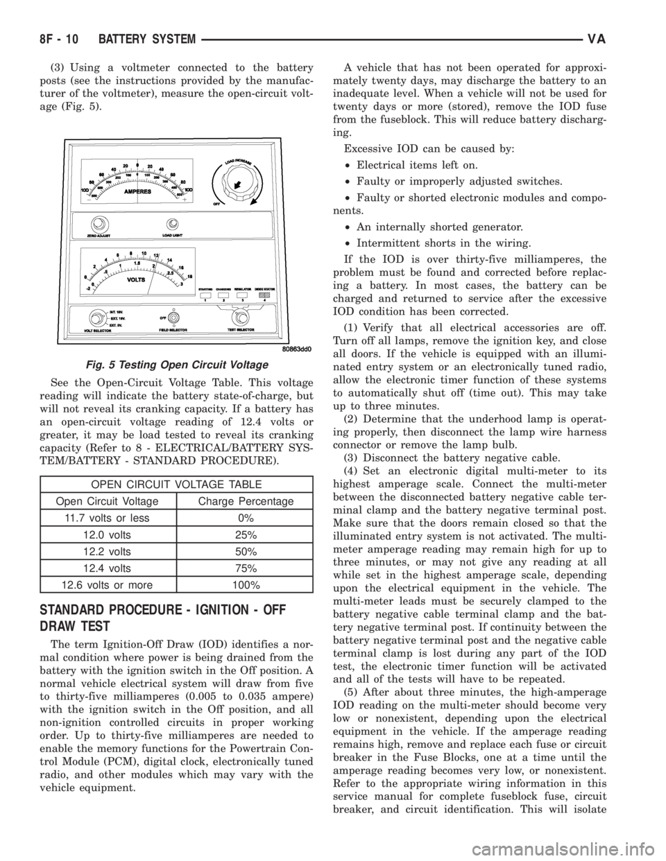
(3) Using a voltmeter connected to the battery
posts (see the instructions provided by the manufac-
turer of the voltmeter), measure the open-circuit volt-
age (Fig. 5).
See the Open-Circuit Voltage Table. This voltage
reading will indicate the battery state-of-charge, but
will not reveal its cranking capacity. If a battery has
an open-circuit voltage reading of 12.4 volts or
greater, it may be load tested to reveal its cranking
capacity (Refer to 8 - ELECTRICAL/BATTERY SYS-
TEM/BATTERY - STANDARD PROCEDURE).
OPEN CIRCUIT VOLTAGE TABLE
Open Circuit Voltage Charge Percentage
11.7 volts or less 0%
12.0 volts 25%
12.2 volts 50%
12.4 volts 75%
12.6 volts or more 100%
STANDARD PROCEDURE - IGNITION - OFF
DRAW TEST
The term Ignition-Off Draw (IOD) identifies a nor-
mal condition where power is being drained from the
battery with the ignition switch in the Off position. A
normal vehicle electrical system will draw from five
to thirty-five milliamperes (0.005 to 0.035 ampere)
with the ignition switch in the Off position, and all
non-ignition controlled circuits in proper working
order. Up to thirty-five milliamperes are needed to
enable the memory functions for the Powertrain Con-
trol Module (PCM), digital clock, electronically tuned
radio, and other modules which may vary with the
vehicle equipment.A vehicle that has not been operated for approxi-
mately twenty days, may discharge the battery to an
inadequate level. When a vehicle will not be used for
twenty days or more (stored), remove the IOD fuse
from the fuseblock. This will reduce battery discharg-
ing.
Excessive IOD can be caused by:
²Electrical items left on.
²Faulty or improperly adjusted switches.
²Faulty or shorted electronic modules and compo-
nents.
²An internally shorted generator.
²Intermittent shorts in the wiring.
If the IOD is over thirty-five milliamperes, the
problem must be found and corrected before replac-
ing a battery. In most cases, the battery can be
charged and returned to service after the excessive
IOD condition has been corrected.
(1) Verify that all electrical accessories are off.
Turn off all lamps, remove the ignition key, and close
all doors. If the vehicle is equipped with an illumi-
nated entry system or an electronically tuned radio,
allow the electronic timer function of these systems
to automatically shut off (time out). This may take
up to three minutes.
(2) Determine that the underhood lamp is operat-
ing properly, then disconnect the lamp wire harness
connector or remove the lamp bulb.
(3) Disconnect the battery negative cable.
(4) Set an electronic digital multi-meter to its
highest amperage scale. Connect the multi-meter
between the disconnected battery negative cable ter-
minal clamp and the battery negative terminal post.
Make sure that the doors remain closed so that the
illuminated entry system is not activated. The multi-
meter amperage reading may remain high for up to
three minutes, or may not give any reading at all
while set in the highest amperage scale, depending
upon the electrical equipment in the vehicle. The
multi-meter leads must be securely clamped to the
battery negative cable terminal clamp and the bat-
tery negative terminal post. If continuity between the
battery negative terminal post and the negative cable
terminal clamp is lost during any part of the IOD
test, the electronic timer function will be activated
and all of the tests will have to be repeated.
(5) After about three minutes, the high-amperage
IOD reading on the multi-meter should become very
low or nonexistent, depending upon the electrical
equipment in the vehicle. If the amperage reading
remains high, remove and replace each fuse or circuit
breaker in the Fuse Blocks, one at a time until the
amperage reading becomes very low, or nonexistent.
Refer to the appropriate wiring information in this
service manual for complete fuseblock fuse, circuit
breaker, and circuit identification. This will isolate
Fig. 5 Testing Open Circuit Voltage
8F - 10 BATTERY SYSTEMVA
Page 880 of 2305
The following operation will require a voltmeter
accurate to 1/10 (0.10) volt. Before performing this
test, be certain that the following procedures are
accomplished:
²The battery is fully-charged and tested. (Refer to
8 - ELECTRICAL/BATTERY SYSTEM/BATTERY -
STANDARD PROCEDURE).
²Fully engage the parking brake.
²Place the automatic transmission gearshift selec-
tor lever in the Park position.
²Verify that all lamps and accessories are turned
off.
²Prevent the engine from starting.
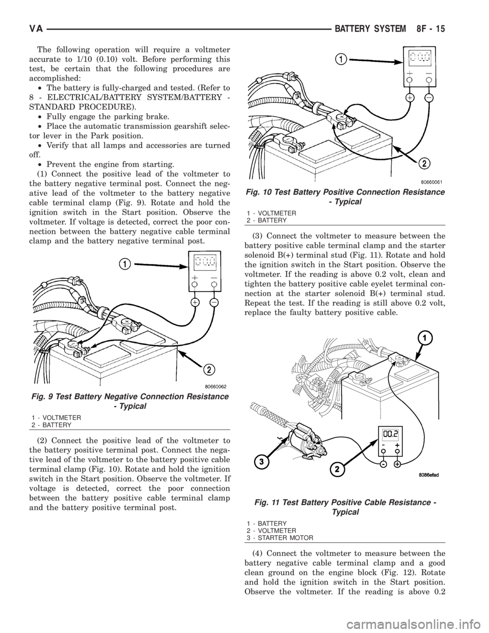
(1) Connect the positive lead of the voltmeter to
the battery negative terminal post. Connect the neg-
ative lead of the voltmeter to the battery negative
cable terminal clamp (Fig. 9). Rotate and hold the
ignition switch in the Start position. Observe the
voltmeter. If voltage is detected, correct the poor con-
nection between the battery negative cable terminal
clamp and the battery negative terminal post.
(2) Connect the positive lead of the voltmeter to
the battery positive terminal post. Connect the nega-
tive lead of the voltmeter to the battery positive cable
terminal clamp (Fig. 10). Rotate and hold the ignition
switch in the Start position. Observe the voltmeter. If
voltage is detected, correct the poor connection
between the battery positive cable terminal clamp
and the battery positive terminal post.(3) Connect the voltmeter to measure between the
battery positive cable terminal clamp and the starter
solenoid B(+) terminal stud (Fig. 11). Rotate and hold
the ignition switch in the Start position. Observe the
voltmeter. If the reading is above 0.2 volt, clean and
tighten the battery positive cable eyelet terminal con-
nection at the starter solenoid B(+) terminal stud.
Repeat the test. If the reading is still above 0.2 volt,
replace the faulty battery positive cable.
(4) Connect the voltmeter to measure between the
battery negative cable terminal clamp and a good
clean ground on the engine block (Fig. 12). Rotate
and hold the ignition switch in the Start position.
Observe the voltmeter. If the reading is above 0.2
Fig. 9 Test Battery Negative Connection Resistance
- Typical
1 - VOLTMETER
2 - BATTERY
Fig. 10 Test Battery Positive Connection Resistance
- Typical
1 - VOLTMETER
2 - BATTERY
Fig. 11 Test Battery Positive Cable Resistance -
Typical
1 - BATTERY
2 - VOLTMETER
3 - STARTER MOTOR
VABATTERY SYSTEM 8F - 15
Page 881 of 2305

volt, clean and tighten the battery negative cable
eyelet terminal connection to the engine block.
Repeat the test. If the reading is still above 0.2 volt,
replace the faulty battery negative cable.
REMOVAL
(1) Turn the ignition switch to the Off position. Be
certain that all electrical accessories are turned off.
(2) Disconnect and isolate the remote battery neg-
ative cable terminal.
(3) One at a time, trace and disconnect the battery
cable retaining pushpins, fasteners and routing clips
until the cables are free from the vehicle.
(4) Feed the battery cable assembly out of the
vehicle.
INSTALLATION
(1) Position the battery cable in the vehicle.
(2) One at a time, install the battery cable retain-
ing pushpins, fasteners and routing clips until the
cable is installed exactly in the factory installed loca-
tion in the vehicle. Refer to the Wiring Diagram sec-
tion of the service manual for reference.
(3) Connect the battery negative cable terminal.
BATTERY TRAY
DESCRIPTION
The battery is mounted in a stamped steel battery
tray located in the left front corner of the engine
compartment. The battery tray is secured with bolts
to the left front wheelhouse inner steel panel. A hole
in the bottom of the battery tray is fitted with aformed drain tube. A second hole in the bottom of the
tray is fitted with a battery temperature sensor.
OPERATION
The battery tray provides a mounting location and
support for the vehicle battery. The battery tray sup-
port supports the battery tray and provides an
anchor point for the inboard battery hold down hard-
ware. The battery tray and the battery hold down
hardware combine to secure and stabilize the battery
in the engine compartment, which prevents battery
movement during vehicle operation. Unrestrained
battery movement during vehicle operation could
result in damage to the vehicle, the battery or both.
The battery tray drain tube directs spilled water or
electrolyte from a leaking battery to the ground
through another hole in the front extension of the
left front wheelhouse inner panel.
REMOVAL
(1) Remove the battery from the battery tray.
(Refer to 8 - ELECTRICAL/BATTERY SYSTEM/BAT-
TERY - REMOVAL).
(2) Remove the battery temperature sensor from
the battery tray. (Refer to 8 - ELECTRICAL/CHARG-
ING/BATTERY TEMPERATURE SENSOR -
REMOVAL).
(3) Remove the bolts that secure the battery tray
to the battery tray support.
(4) Remove the battery tray from the vehicle.
INSTALLATION
(1) Clean and inspect the battery tray. (Refer to 8 -
ELECTRICAL/BATTERY SYSTEM - CLEANING).
(2) Position the battery tray onto the battery tray
support.
(3) Install and tighten the bolts that secure the
battery tray to the battery tray support. Tighten the
screws to 11.8 N´m (105 in. lbs.).
(4) Install the battery temperature sensor onto the
battery tray. (Refer to 8 - ELECTRICAL/CHARGING/
BATTERY TEMPERATURE SENSOR - INSTALLA-
TION).
(5) Install the battery onto the battery tray. (Refer
to 8 - ELECTRICAL/BATTERY SYSTEM/BATTERY -
INSTALLATION).
Fig. 12 Test Ground Circuit Resistance - Typical
1 - VOLTMETER
2 - BATTERY
3 - ENGINE GROUND
8F - 16 BATTERY SYSTEMVA
Page 885 of 2305
DIAGNOSIS AND TESTING - GENERATOR DECOUPLER
CONDITION POSSIBLE CAUSES CORRECTION
Does not drive generator
(generator not charging)Internal failure Replace decoupler
Noise coming from decou-
plerInternal failure Replace decoupler
REMOVAL
The generator decoupler is used only with
certain engines.
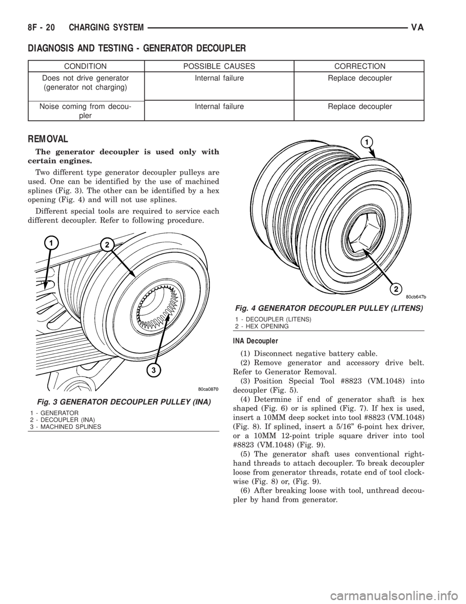
Two different type generator decoupler pulleys are
used. One can be identified by the use of machined
splines (Fig. 3). The other can be identified by a hex
opening (Fig. 4) and will not use splines.
Different special tools are required to service each
different decoupler. Refer to following procedure.
INA Decoupler
(1) Disconnect negative battery cable.
(2) Remove generator and accessory drive belt.
Refer to Generator Removal.
(3) Position Special Tool #8823 (VM.1048) into
decoupler (Fig. 5).
(4) Determine if end of generator shaft is hex
shaped (Fig. 6) or is splined (Fig. 7). If hex is used,
insert a 10MM deep socket into tool #8823 (VM.1048)
(Fig. 8). If splined, insert a 5/16º 6-point hex driver,
or a 10MM 12-point triple square driver into tool
#8823 (VM.1048) (Fig. 9).
(5) The generator shaft uses conventional right-
hand threads to attach decoupler. To break decoupler
loose from generator threads, rotate end of tool clock-
wise (Fig. 8) or, (Fig. 9).
(6) After breaking loose with tool, unthread decou-
pler by hand from generator.
Fig. 3 GENERATOR DECOUPLER PULLEY (INA)
1 - GENERATOR
2 - DECOUPLER (INA)
3 - MACHINED SPLINES
Fig. 4 GENERATOR DECOUPLER PULLEY (LITENS)
1 - DECOUPLER (LITENS)
2 - HEX OPENING
8F - 20 CHARGING SYSTEMVA
Page 887 of 2305
Litens Decoupler
(1) Disconnect negative battery cable.
(2) Remove generator and accessory drive belt.
Refer to Generator Removal.
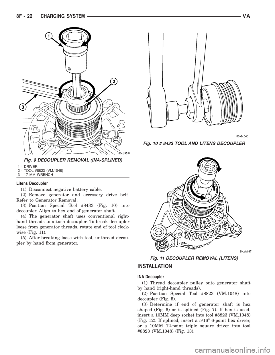
(3) Position Special Tool #8433 (Fig. 10) into
decoupler. Align to hex end of generator shaft.
(4) The generator shaft uses conventional right-
hand threads to attach decoupler. To break decoupler
loose from generator threads, rotate end of tool clock-
wise (Fig. 11).
(5) After breaking loose with tool, unthread decou-
pler by hand from generator.
INSTALLATION
INA Decoupler
(1) Thread decoupler pulley onto generator shaft
by hand (right-hand threads).
(2) Position Special Tool #8823 (VM.1048) into
decoupler (Fig. 5).
(3) Determine if end of generator shaft is hex
shaped (Fig. 6) or is splined (Fig. 7). If hex is used,
insert a 10MM deep socket into tool #8823 (VM.1048)
(Fig. 12). If splined, insert a 5/16º 6-point hex driver,
or a 10MM 12-point triple square driver into tool
#8823 (VM.1048) (Fig. 13).
Fig. 9 DECOUPLER REMOVAL (INA-SPLINED)
1 - DRIVER
2 - TOOL #8823 (VM.1048)
3 - 17 MM WRENCH
Fig. 10 # 8433 TOOL AND LITENS DECOUPLER
Fig. 11 DECOUPLER REMOVAL (LITENS)
8F - 22 CHARGING SYSTEMVA
Page 888 of 2305
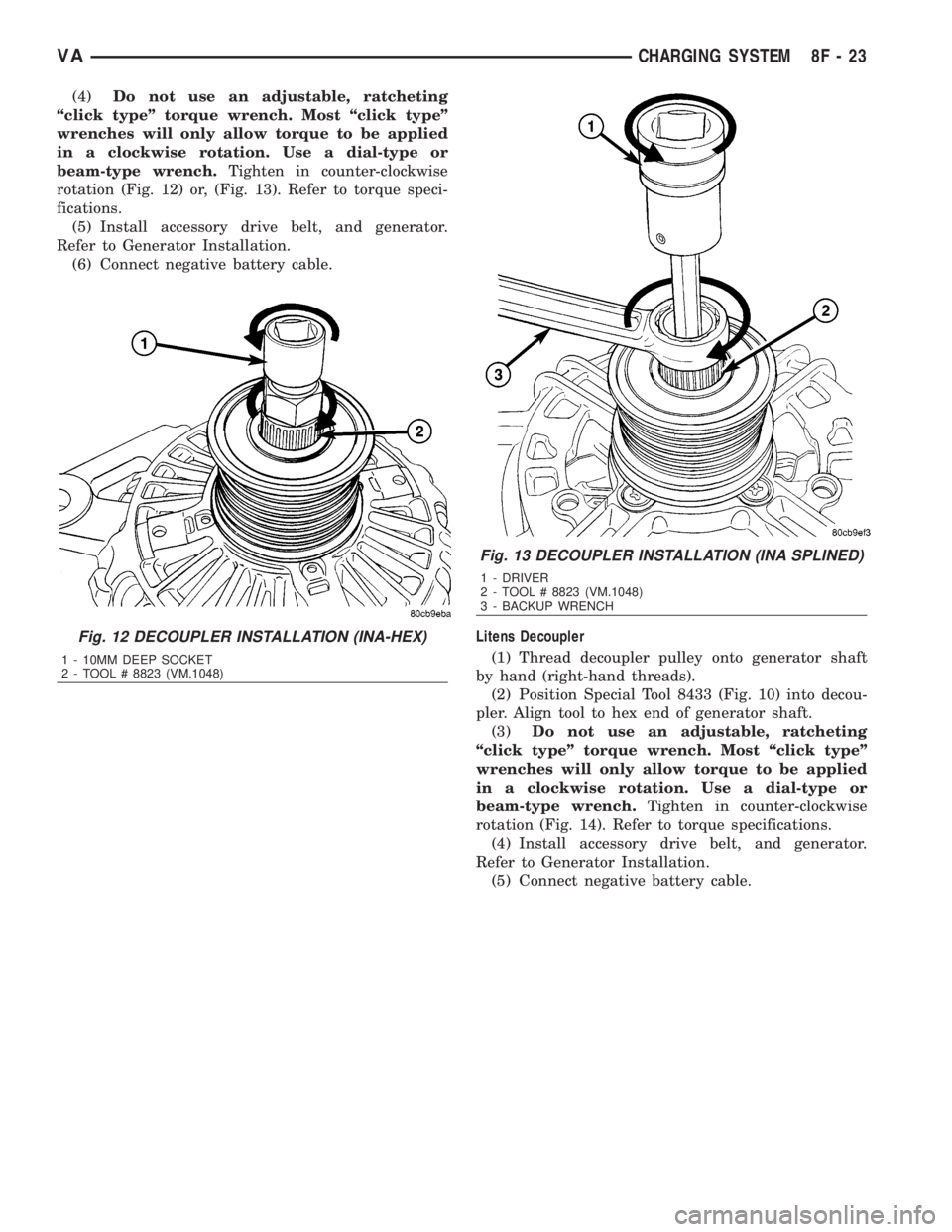
(4)Do not use an adjustable, ratcheting
ªclick typeº torque wrench. Most ªclick typeº
wrenches will only allow torque to be applied
in a clockwise rotation. Use a dial-type or
beam-type wrench.Tighten in counter-clockwise
rotation (Fig. 12) or, (Fig. 13). Refer to torque speci-
fications.
(5) Install accessory drive belt, and generator.
Refer to Generator Installation.
(6) Connect negative battery cable.
Litens Decoupler
(1) Thread decoupler pulley onto generator shaft
by hand (right-hand threads).
(2) Position Special Tool 8433 (Fig. 10) into decou-
pler. Align tool to hex end of generator shaft.
(3)Do not use an adjustable, ratcheting
ªclick typeº torque wrench. Most ªclick typeº
wrenches will only allow torque to be applied
in a clockwise rotation. Use a dial-type or
beam-type wrench.Tighten in counter-clockwise
rotation (Fig. 14). Refer to torque specifications.
(4) Install accessory drive belt, and generator.
Refer to Generator Installation.
(5) Connect negative battery cable.
Fig. 12 DECOUPLER INSTALLATION (INA-HEX)
1 - 10MM DEEP SOCKET
2 - TOOL # 8823 (VM.1048)
Fig. 13 DECOUPLER INSTALLATION (INA SPLINED)
1 - DRIVER
2 - TOOL # 8823 (VM.1048)
3 - BACKUP WRENCH
VACHARGING SYSTEM 8F - 23
Page 893 of 2305

STARTING SYSTEM
TABLE OF CONTENTS
page page
STARTING SYSTEM
DESCRIPTION.........................28
OPERATION...........................28
DIAGNOSIS AND TESTING - STARTING
SYSTEM............................29
SPECIFICATIONS
TORQUE - STARTER - DIESEL...........33
SPECIFICATIONS - STARTER MOTOR -
DIESEL.............................33STARTER MOTOR
DIAGNOSIS AND TESTING - STARTER
MOTOR .............................33
REMOVAL.............................34
INSTALLATION.........................35
STARTER MOTOR RELAY
DESCRIPTION.........................35
REMOVAL.............................35
INSTALLATION.........................36
STARTING SYSTEM
DESCRIPTION
The starting system consists of:
²Starter relay
²Starter motor (including an integral starter sole-
noid)
Other components to be considered as part of start-
ing system are:
²Battery
²Battery cables
²Ignition switch and key lock cylinder
²Park/neutral position switch (automatic trans-
mission)
²Wire harnesses and connections.
The Battery, Starting, and Charging systems oper-
ate in conjunction with one another, and must be
tested as a complete system. For correct operation of
starting/charging systems, all components used in
these 3 systems must perform within specifications.
When attempting to diagnose any of these systems, it
is important that you keep their interdependency in
mind.
The diagnostic procedures used in each of these
groups include the most basic conventional diagnostic
methods, to the more sophisticated On-Board Diag-
nostics (OBD) built into the Engine Control Module
(ECM). Use of an induction-type milliampere amme-
ter, volt/ohmmeter, battery charger, carbon pile rheo-
stat (load tester), and 12-volt test lamp may be
required.
Certain starting system components are monitored
by the ECM and may produce a Diagnostic Trouble
Code (DTC).
OPERATION
The starting system components form two separate
circuits. A high-amperage feed circuit that feeds the
starter motor high-amperage, and a low-amperagecontrol circuit that operates on less than 20 amperes.
The high-amperage feed circuit components include
the battery, the battery cables, the contact disc por-
tion of the starter solenoid, and the starter motor
itself. The low-amperage control circuit components
include the ignition switch, the park/neutral position
switch (automatic transmission), the starter relay,
the electromagnetic windings of the starter solenoid,
and the connecting wire harness components.
If the vehicle is equipped with an automatic trans-
mission, battery voltage is supplied through the low-
amperage control circuit to the coil battery terminal
of the starter relay when the ignition switch is
turned to the momentary Start position. The park/
neutral position switch is installed in series between
the starter relay coil ground terminal and ground.
This normally open switch prevents the starter relay
from being energized and the starter motor from
operating unless the automatic transmission gear
selector is in the Neutral or Park positions.
When the starter relay coil is energized, the nor-
mally open relay contacts close. The relay contacts
connect the relay common feed terminal to the relay
normally open terminal. The closed relay contacts
energize the starter solenoid coil windings.
The energized solenoid pull-in coil pulls in the sole-
noid plunger. The solenoid plunger pulls the shift
lever in the starter motor. This engages the starter
overrunning clutch and pinion gear with the starter
ring gear on the manual transmission flywheel or on
the automatic transmission torque converter or
torque converter drive plate.
As the solenoid plunger reaches the end of its
travel, the solenoid contact disc completes the high-
amperage starter feed circuit and energizes the sole-
noid plunger hold-in coil. Current now flows between
the solenoid battery terminal and the starter motor,
energizing the starter.
Once the engine starts, the overrunning clutch pro-
tects the starter motor from damage by allowing the
8F - 28 STARTING SYSTEMVA