2006 MERCEDES-BENZ SPRINTER lock
[x] Cancel search: lockPage 690 of 2305
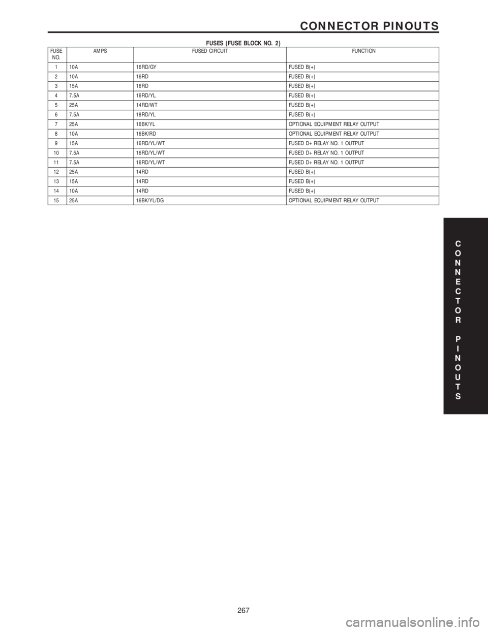
FUSES (FUSE BLOCK NO. 2)FUSE
NO.AMPS FUSED CIRCUIT FUNCTION
1 10A 16RD/GY FUSED B(+)
2 10A 16RD FUSED B(+)
3 15A 16RD FUSED B(+)
4 7.5A 16RD/YL FUSED B(+)
5 25A 14RD/WT FUSED B(+)
6 7.5A 18RD/YL FUSED B(+)
7 25A 16BK/YL OPTIONAL EQUIPMENT RELAY OUTPUT
8 10A 16BK/RD OPTIONAL EQUIPMENT RELAY OUTPUT
9 15A 16RD/YL/WT FUSED D+ RELAY NO. 1 OUTPUT
10 7.5A 16RD/YL/WT FUSED D+ RELAY NO. 1 OUTPUT
11 7.5A 16RD/YL/WT FUSED D+ RELAY NO. 1 OUTPUT
12 25A 14RD FUSED B(+)
13 15A 14RD FUSED B(+)
14 10A 14RD FUSED B(+)
15 25A 16BK/YL/DG OPTIONAL EQUIPMENT RELAY OUTPUT
C
O
N
N
E
C
T
O
R
P
I
N
O
U
T
S
267
CONNECTOR PINOUTS
Page 692 of 2305
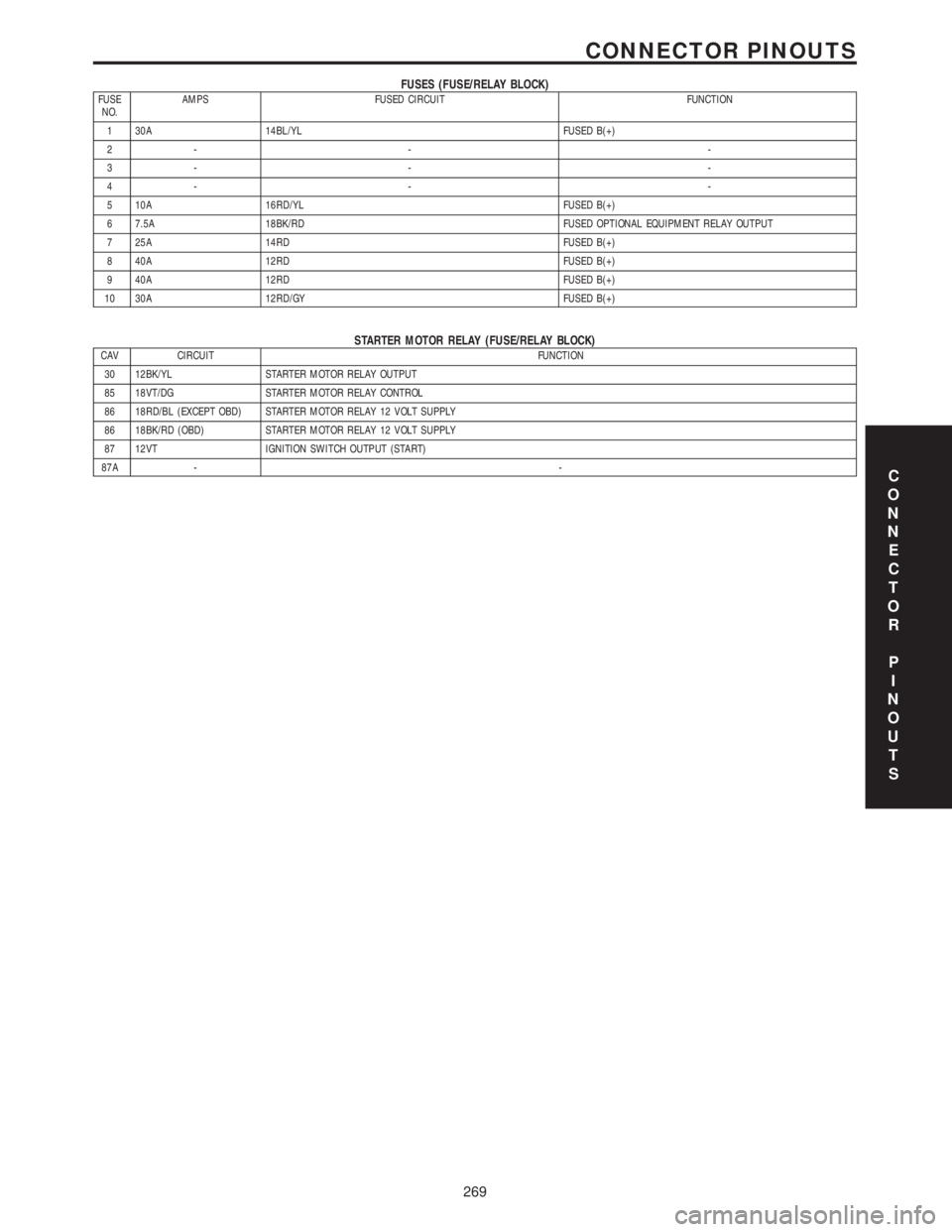
FUSES (FUSE/RELAY BLOCK)FUSE
NO.AMPS FUSED CIRCUIT FUNCTION
1 30A 14BL/YL FUSED B(+)
2- - -
3- - -
4- - -
5 10A 16RD/YL FUSED B(+)
6 7.5A 18BK/RD FUSED OPTIONAL EQUIPMENT RELAY OUTPUT
7 25A 14RD FUSED B(+)
8 40A 12RD FUSED B(+)
9 40A 12RD FUSED B(+)
10 30A 12RD/GY FUSED B(+)
STARTER MOTOR RELAY (FUSE/RELAY BLOCK)CAV CIRCUIT FUNCTION
30 12BK/YL STARTER MOTOR RELAY OUTPUT
85 18VT/DG STARTER MOTOR RELAY CONTROL
86 18RD/BL (EXCEPT OBD) STARTER MOTOR RELAY 12 VOLT SUPPLY
86 18BK/RD (OBD) STARTER MOTOR RELAY 12 VOLT SUPPLY
87 12VT IGNITION SWITCH OUTPUT (START)
87A --
C
O
N
N
E
C
T
O
R
P
I
N
O
U
T
S
269
CONNECTOR PINOUTS
Page 696 of 2305

FUSED IGNITION SWITCH RUN-START RELAY (RELAY BLOCK)CAV CIRCUIT FUNCTION
30 14RD FUSED B(+)
85 18BK FUSED IGNITION SWITCH OUTPUT (RUN-START)
86 16BR GROUND
87 14BK/YL FUSED IGNITION SWITCH RUN-START RELAY OUTPUT
87A --
SPEED CONTROL SWITCHCAV CIRCUIT FUNCTION
1 18GY OFF SIGNAL
2 18BK VERIFICATION SIGNAL
3 18BL RESUME SIGNAL
4 18YL DECEL/SET SIGNAL
5 18DG ACCEL/SET SIGNAL
6 18RD S/C SWITCH 12 VOLT SUPPLY
WATER IN FUEL SENSOR - BLACKCAV CIRCUIT FUNCTION
1 18BR WATER IN FUEL SENSOR GROUND
2 18BR/RD WATER IN FUEL SENSOR 12 VOLT SUPPLY
3 18BK/YL WATER IN FUEL SENSOR SIGNAL
C
O
N
N
E
C
T
O
R
P
I
N
O
U
T
S
273
CONNECTOR PINOUTS
Page 717 of 2305
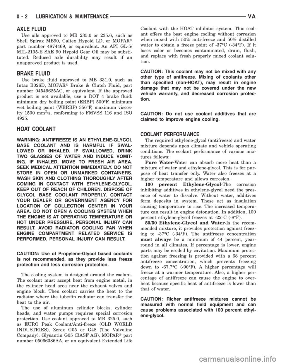
AXLE FLUID
Use oils approved to MB 235.0 or 235.6, such as
Shell Spirax MB90, Caltex Hypoid LD, or MOPARt
part number 4874469, or equivalent. An API GL-5/
MIL-2105-E SAE 90 Hypoid Gear Oil may be substi-
tuted. Reduced axle durability may result if an
unapproved product is used.
BRAKE FLUID
Use brake fluid approved to MB 331.0, such as
Intac B026D, MOPARtBrake & Clutch Fluid, part
number 04549625AC, or equivalent. If the approved
product is not available, use a DOT 4 brake fluid:
minimum dry boiling point (ERBP) 500ÉF, minimum
wet boiling point (WERBP) 356ÉF, maximum viscos-
ity 1500 mm
2/s, conforming to FMVSS 116 and ISO
4925.
HOAT COOLANT
WARNING: ANTIFREEZE IS AN ETHYLENE-GLYCOL
BASE COOLANT AND IS HARMFUL IF SWAL-
LOWED OR INHALED. IF SWALLOWED, DRINK
TWO GLASSES OF WATER AND INDUCE VOMIT-
ING. IF INHALED, MOVE TO FRESH AIR AREA.
SEEK MEDICAL ATTENTION IMMEDIATELY. DO NOT
STORE IN OPEN OR UNMARKED CONTAINERS.
WASH SKIN AND CLOTHING THOROUGHLY AFTER
COMING IN CONTACT WITH ETHYLENE-GLYCOL.
KEEP OUT OF REACH OF CHILDREN. DISPOSE OF
GLYCOL BASE COOLANT PROPERLY, CONTACT
YOUR DEALER OR GOVERNMENT AGENCY FOR
LOCATION OF COLLECTION CENTER IN YOUR
AREA. DO NOT OPEN A COOLING SYSTEM WHEN
THE ENGINE IS AT OPERATING TEMPERATURE OR
HOT UNDER PRESSURE, PERSONAL INJURY CAN
RESULT. AVOID RADIATOR COOLING FAN WHEN
ENGINE COMPARTMENT RELATED SERVICE IS
PERFORMED, PERSONAL INJURY CAN RESULT.
CAUTION: Use of Propylene-Glycol based coolants
is not recommended, as they provide less freeze
protection and less corrosion protection.
The cooling system is designed around the coolant.
The coolant must accept heat from engine metal, in
the cylinder head area near the exhaust valves and
engine block. Then coolant carries the heat to the
radiator where the tube/fin radiator can transfer the
heat to the air.
The use of aluminum cylinder blocks, cylinder
heads, and water pumps requires special corrosion
protection. Use coolant approved to MB 325.0, such
as EURO Peak Coolant/Anti-freeze (OLD WORLD
INDUSTRIES), Zerex G05 or G48 (The Valvoline
Company), Glysantin G05 (BASF AG), MOPARtpart
number 05066386AA, or an equivalent Extended LifeCoolant with the HOAT inhibitor system. This cool-
ant offers the best engine cooling without corrosion
when mixed with 50% anti-freeze and 50% distilled
water to obtain a freeze point of -37ÉC (-34ÉF). If it
loses color or becomes contaminated, drain, flush,
and replace with fresh properly mixed coolant solu-
tion.
CAUTION: This coolant may not be mixed with any
other type of antifreeze. Mixing of coolants other
than specified (non-HOAT), may result in engine
damage that may not be covered under the new
vehicle warranty, and decreased corrosion protec-
tion.
CAUTION: Do not use coolant additives that are
claimed to improve engine cooling.
COOLANT PERFORMANCE
The required ethylene-glycol (antifreeze) and water
mixture depends upon climate and vehicle operating
conditions. The coolant performance of various mix-
tures follows:
Pure Water-Water can absorb more heat than a
mixture of water and ethylene-glycol. This is for pur-
pose of heat transfer only. Water also freezes at a
higher temperature and allows corrosion.
100 percent Ethylene-Glycol-The corrosion
inhibiting additives in ethylene-glycol need the pres-
ence of water to dissolve. Without water, additives
form deposits in system. These act as insulation
causing temperature to rise. The increased tempera-
ture can result in engine detonation. In addition, 100
percent ethylene-glycol freezes at -22ÉC (-8ÉF).
50/50 Ethylene-Glycol and Water-Is the recom-
mended mixture, it provides protection against freez-
ing to -37ÉC (-34ÉF). The antifreeze concentration
must alwaysbe a minimum of 44 percent, year-
round in all climates. If percentage is lower, engine
parts may be eroded by cavitation. Maximum protec-
tion against freezing is provided with a 68 percent
antifreeze concentration, which prevents freezing
down to -67.7ÉC (-90ÉF). A higher percentage will
freeze at a warmer temperature. Also, a higher per-
centage of antifreeze can cause the engine to over-
heat because specific heat of antifreeze is lower than
that of water.
CAUTION: Richer antifreeze mixtures cannot be
measured with normal field equipment and can
cause problems associated with 100 percent ethyl-
ene-glycol.
0 - 2 LUBRICATION & MAINTENANCEVA
Page 722 of 2305
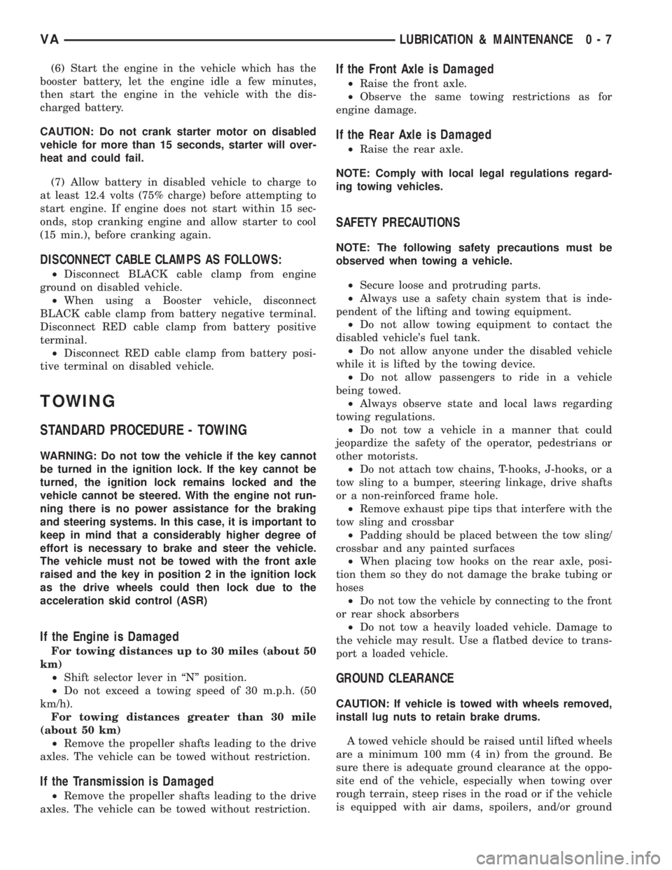
(6) Start the engine in the vehicle which has the
booster battery, let the engine idle a few minutes,
then start the engine in the vehicle with the dis-
charged battery.
CAUTION: Do not crank starter motor on disabled
vehicle for more than 15 seconds, starter will over-
heat and could fail.
(7) Allow battery in disabled vehicle to charge to
at least 12.4 volts (75% charge) before attempting to
start engine. If engine does not start within 15 sec-
onds, stop cranking engine and allow starter to cool
(15 min.), before cranking again.
DISCONNECT CABLE CLAMPS AS FOLLOWS:
²Disconnect BLACK cable clamp from engine
ground on disabled vehicle.
²When using a Booster vehicle, disconnect
BLACK cable clamp from battery negative terminal.
Disconnect RED cable clamp from battery positive
terminal.
²Disconnect RED cable clamp from battery posi-
tive terminal on disabled vehicle.
TOWING
STANDARD PROCEDURE - TOWING
WARNING: Do not tow the vehicle if the key cannot
be turned in the ignition lock. If the key cannot be
turned, the ignition lock remains locked and the
vehicle cannot be steered. With the engine not run-
ning there is no power assistance for the braking
and steering systems. In this case, it is important to
keep in mind that a considerably higher degree of
effort is necessary to brake and steer the vehicle.
The vehicle must not be towed with the front axle
raised and the key in position 2 in the ignition lock
as the drive wheels could then lock due to the
acceleration skid control (ASR)
If the Engine is Damaged
For towing distances up to 30 miles (about 50
km)
²Shift selector lever in ªNº position.
²Do not exceed a towing speed of 30 m.p.h. (50
km/h).
For towing distances greater than 30 mile
(about 50 km)
²Remove the propeller shafts leading to the drive
axles. The vehicle can be towed without restriction.
If the Transmission is Damaged
²Remove the propeller shafts leading to the drive
axles. The vehicle can be towed without restriction.
If the Front Axle is Damaged
²Raise the front axle.
²Observe the same towing restrictions as for
engine damage.
If the Rear Axle is Damaged
²Raise the rear axle.
NOTE: Comply with local legal regulations regard-
ing towing vehicles.
SAFETY PRECAUTIONS
NOTE: The following safety precautions must be
observed when towing a vehicle.
²Secure loose and protruding parts.
²Always use a safety chain system that is inde-
pendent of the lifting and towing equipment.
²Do not allow towing equipment to contact the
disabled vehicle's fuel tank.
²Do not allow anyone under the disabled vehicle
while it is lifted by the towing device.
²Do not allow passengers to ride in a vehicle
being towed.
²Always observe state and local laws regarding
towing regulations.
²Do not tow a vehicle in a manner that could
jeopardize the safety of the operator, pedestrians or
other motorists.
²Do not attach tow chains, T-hooks, J-hooks, or a
tow sling to a bumper, steering linkage, drive shafts
or a non-reinforced frame hole.
²Remove exhaust pipe tips that interfere with the
tow sling and crossbar
²Padding should be placed between the tow sling/
crossbar and any painted surfaces
²When placing tow hooks on the rear axle, posi-
tion them so they do not damage the brake tubing or
hoses
²Do not tow the vehicle by connecting to the front
or rear shock absorbers
²Do not tow a heavily loaded vehicle. Damage to
the vehicle may result. Use a flatbed device to trans-
port a loaded vehicle.
GROUND CLEARANCE
CAUTION: If vehicle is towed with wheels removed,
install lug nuts to retain brake drums.
A towed vehicle should be raised until lifted wheels
are a minimum 100 mm (4 in) from the ground. Be
sure there is adequate ground clearance at the oppo-
site end of the vehicle, especially when towing over
rough terrain, steep rises in the road or if the vehicle
is equipped with air dams, spoilers, and/or ground
VALUBRICATION & MAINTENANCE 0 - 7
Page 723 of 2305
effect panels. If necessary, remove the wheels from
the lifted end of the vehicle and lower the vehicle
closer to the ground, to increase the ground clearance
at the opposite end of the vehicle. Install lug nuts on
wheel attaching studs to retain brake drums.
RAMP ANGLE
If a vehicle with flat-bed towing equipment is used,
the approach ramp angle should not exceed 15
degrees.
TOWING WHEN KEYS ARE NOT AVAILABLE
When the vehicle is locked and keys are not avail-
able, use a flat bed hauler. A Wheel-lift or Sling-type
device can be used provided all the wheels are lifted
off the ground using tow dollies.
MAINTENANCE SCHEDULES
DESCRIPTION
The use of special lubricant additives is not recom-
mended. The use of such additives may affect the
warranty rights. With regard to legal stipulations
concerning emissions control, please note that
engines have to be serviced and adjusted in accor-
dance with special instructions and using special
measuring equipment. Modifications to or interfer-
ence with the emissions control systems are not per-
missible.
MAINTENANCE - WITHOUT ASSYST MAINTE-
NANCE COMPUTER
Maintenance Intervals
²Oil service ±Normal Operationevery 10,000
miles or 16,000 km or 12 months.
²Maintenance service every 30,000 miles or
48,000 km.
Additional work must be carried out at yearly
intervals.
MAINTENANCE - WITH ASSYST MAINTENANCE
COMPUTER
ASSYST provides information on the best possible
timing for maintenance work.
When the next maintenance service is due, this
will be indicated in the multi-function display with
the wrench icon symbol displayed in km/miles or
days.
²One wrench icon showing indicates Oil Service
is necessary.
²Two wrench icons showing indicates Mainte-
nance Service is necessary ± displayed in km/miles or
days.
If the display shows the number of days, a clock
symbol will also appear in the multi-function display.You should have the maintenance performed
within the stated period/distance.
The service indicator will be reset after an oil ser-
vice and/or maintenance service has been performed.
REGULAR CHECK - UPS
To maintain the safe operation of the vehicle, it is
recommended that the following tasks be performed
on a regular basis (i.e. weekly or whenever the vehi-
cle is refueled). Check:
²Engine oil level
²Brake system - fluid level
²Battery - acid level
²Windshield washer system and headlamp clean-
ing system - fluid level
²Mechanical assemblies (e.g. engine, transmis-
sion, etc.) - check for leaks
²Condition of tires and tires pressures
²All exterior lights
SPECIAL MAINTENANCE REQUIREMENTS
If bodies built by manufacturers other than
DaimlerChrysler Corporation are fitted to the vehi-
cle, the maintenance requirements and lubrication
intervals specified by the body manufacturer must be
adhered to, in addition to all standard maintenance
requirements.
Coolant
Corrosion inhibitor/antifreeze concentration in the
coolant should be checked before the onset of winter
(once year in countries with high prevailing temper-
atures).
Replace the coolant every five years or 100,000
miles.
Dust Filter for Heating / Ventilation Replacement
The dust filter and the tailgate interior filter are to
be renewed during routine maintenance service. If
operating conditions are dusty, these filters should be
renewed more frequently.
ENGINE OIL CHANGE AND FILTER REPLACEMENT
At a minimum, change the engine oil and oil filter
once a year ± even if the vehicle mileage per year is
extremely low. For standard oil service schedules
refer to the chapter oil service and maintenance ser-
vice.
Once a Year
Select the viscosity of the engine oil (SAE classes)
according to the outside air temperature.
Only use engine oil approved by DaimlerChrysler
Corporation if following the ASSYST system guide-
lines.
0 - 8 LUBRICATION & MAINTENANCEVA
Page 727 of 2305
DESCRIPTION N´m Ft. Lbs. In. Lbs.
Bottom Spring Clamp
Plate To Front Axle
M10 Bolt65 48 Ð
Sway Bar Clamp To The
Front Axle30 22 Ð
Hexagon Socket Bolt For
Clamping Nut To Adjust
Wheel Bearing Play12 9 106
Lower Control Arm To
Front Axle Beam150 110 Ð
Stop Plate For Lower
Control Arm60 44 Ð
Outer Tie Rod End Nut 130 96 Ð
Outer Tie Rod End Nut
Jam Nut50 37 Ð
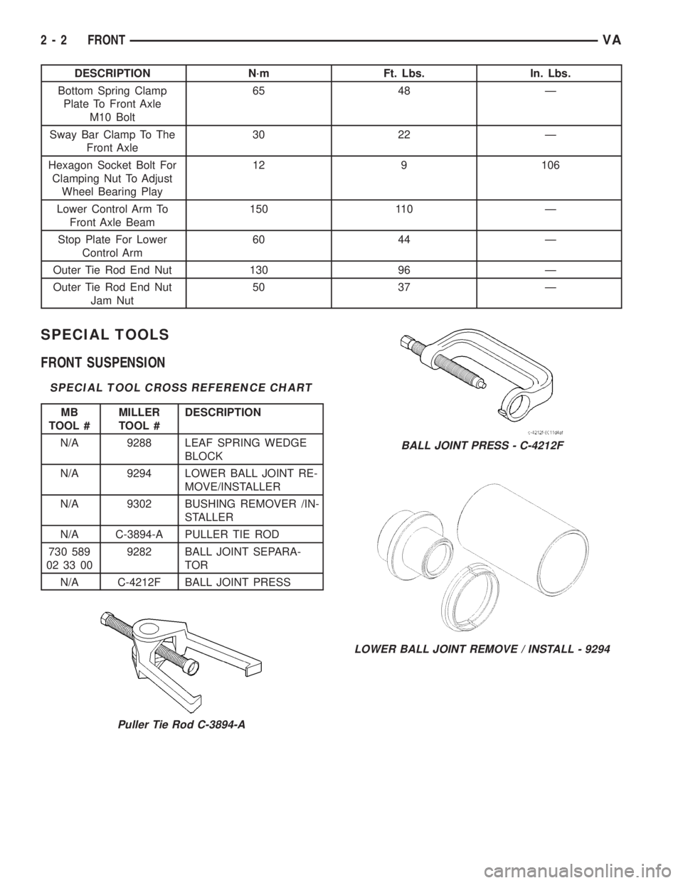
SPECIAL TOOLS
FRONT SUSPENSION
SPECIAL TOOL CROSS REFERENCE CHART
MB
TOOL #MILLER
TOOL #DESCRIPTION
N/A 9288 LEAF SPRING WEDGE
BLOCK
N/A 9294 LOWER BALL JOINT RE-
MOVE/INSTALLER
N/A 9302 BUSHING REMOVER /IN-
STALLER
N/A C-3894-A PULLER TIE ROD
730 589
02 33 009282 BALL JOINT SEPARA-
TOR
N/A C-4212F BALL JOINT PRESS
Puller Tie Rod C-3894-A
BALL JOINT PRESS - C-4212F
LOWER BALL JOINT REMOVE / INSTALL - 9294
2 - 2 FRONTVA
Page 728 of 2305
BUSHINGS
REMOVAL
(1) Remove the lower control arm (Refer to 2 -
SUSPENSION/FRONT/LOWER CONTROL ARM -
REMOVAL).
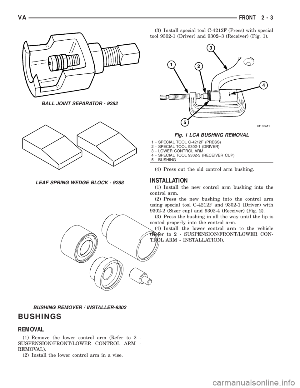
(2) Install the lower control arm in a vise.(3) Install special tool C-4212F (Press) with special
tool 9302-1 (Driver) and 9302±3 (Receiver) (Fig. 1).
(4) Press out the old control arm bushing.
INSTALLATION
(1) Install the new control arm bushing into the
control arm.
(2) Press the new bushing into the control arm
using special tool C-4212F and 9302-1 (Driver) with
9302-2 (Sizer cup) and 9302-4 (Receiver) (Fig. 2).
(3) Press the bushing in all the way until the lip is
seated properly into the control arm.
(4) Install the lower control arm to the vehicle
(Refer to 2 - SUSPENSION/FRONT/LOWER CON-
TROL ARM - INSTALLATION).
BALL JOINT SEPARATOR - 9282
LEAF SPRING WEDGE BLOCK - 9288
BUSHING REMOVER / INSTALLER-9302
Fig. 1 LCA BUSHING REMOVAL
1 - SPECIAL TOOL C-4212F (PRESS)
2 - SPECIAL TOOL 9302-1 (DRIVER)
3 - LOWER CONTROL ARM
4 - SPECIAL TOOL 9302-3 (RECEIVER CUP)
5 - BUSHING
VAFRONT 2 - 3