2006 MERCEDES-BENZ SPRINTER wheel alignment
[x] Cancel search: wheel alignmentPage 393 of 2305

Symptom:
STEERING ANGLE SENSOR IMPLAUSIBLE WHEEL SPEED
POSSIBLE CAUSES
STEERING ANGLE SENSOR INTERMITTENT DTC
STEERING COMPONENT INSPECTION
STEERING ANGLE SENSOR
TEST ACTION APPLICABILITY
1NOTE: If a system undervoltage or overvoltage DTC is set along with this
DTC, diagnose the system voltage DTC first.
NOTE: Electromagnetic (radio) interference can cause an intermittent
system malfunction by interrupting communication between the sensor
and the CAB.
NOTE: The Steering Angle Sensor is very sensitive to changes due to
alignment problems. The sensor must be recalculated using the DRBIIItif
alignment has been changed by more than 5 degrees.
Turn the ignition on.
With the DRBIIIt, erase DTCs.
Test drive the vehicle.
Using the DRBIIIt, perform the road test procedure.
With the DRBIIIt, read DTCs.
NOTE: If the ESP lamp remains illuminated after the test has completed, a
fault code will be set indicating the cause of the failure.
Does this DTC reset?All
Ye s!Go To 2
No!Go To 3
2NOTE: When the vehicle is in a turn, the ESP compares the Steering Angle
Sensor value and the speed of the inner and outer wheels to determine if the
values are plausible.
Inspect the front end and steering components for damage or misalignment.
Inspect the steering column and Steering Angle Sensor for correct mounting and
installation.
Inspect the tires and wheels to make sure that they are the correct size. All tires must
be the same size.
Inspect the left and right Wheel Speed Sensors to make sure they are connected
correctly, i.e. left harness connected to left sensor, etc.
Were any problems found?All
Ye s!Repair or replace components as necessary in accordance with the
Service Information.
No!Replace the Steering Angle Sensor in accordance with the Service
Information.
72
BRAKES (CAB)
Page 395 of 2305

Symptom:
STEERING ANGLE SENSOR INTERNAL FAULT
POSSIBLE CAUSES
STEERING ANGLE SENSOR INTERMITTENT DTC
STEERING ANGLE SENSOR
TEST ACTION APPLICABILITY
1NOTE: If a system undervoltage or overvoltage DTC is set along with this
DTC, diagnose the system voltage DTC first.
NOTE: Electromagnetic (radio) interference can cause an intermittent
system malfunction by interrupting communication between the sensor
and the CAB.
Turn the ignition on.
With the DRBIIIt, erase DTCs.
Move the Steering Wheel from stop to stop several times.
With the DRBIIIt, perform the road test procedure.
With the DRBIIIt, read DTCs.
NOTE: The Steering Angle Sensor is very sensitive to changes due to
alignment problems. The sensor must be recalculated using the DRBIIItif
alignment has been changed by more than 5 degrees.
Does this DTC reset?All
Ye s!Inspect the Steering Angle Sensor for proper installation. Inspect
the wiring and connectors. Repair as necessary. If no other
problems are found, replace the Steering Angle Sensor in accor-
dance with the Service Information.
No!Go To 2
2 The condition that set this DTC is not present at this time.
Monitor the DRBIIItwhile wiggle testing the related harness and connectors. Look
for any related parameters to change or for the DTC to reset.
Inspect the related harness and connectors.
Look for any chafed, pierced, pinched, or partially broken wires.
Look for broken, bent, pushed out, or corroded terminals.
Inspect the tires and wheels to make sure that they are the correct size. All tires must
be the same size.
Inspect the steering column and Steering Angle Sensor for correct mounting and
installation.
Inspect the front end and steering components for damage or misalignment.
Were any problems found?All
Ye s!Repair as necessary.
No!Test Complete.
74
BRAKES (CAB)
Page 726 of 2305
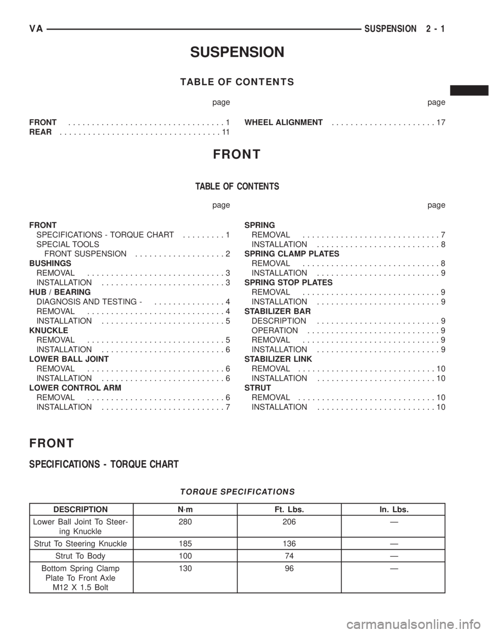
SUSPENSION
TABLE OF CONTENTS
page page
FRONT.................................1
REAR..................................11WHEEL ALIGNMENT......................17
FRONT
TABLE OF CONTENTS
page page
FRONT
SPECIFICATIONS - TORQUE CHART.........1
SPECIAL TOOLS
FRONT SUSPENSION...................2
BUSHINGS
REMOVAL.............................3
INSTALLATION..........................3
HUB / BEARING
DIAGNOSIS AND TESTING -...............4
REMOVAL.............................4
INSTALLATION..........................5
KNUCKLE
REMOVAL.............................5
INSTALLATION..........................6
LOWER BALL JOINT
REMOVAL.............................6
INSTALLATION..........................6
LOWER CONTROL ARM
REMOVAL.............................6
INSTALLATION..........................7SPRING
REMOVAL.............................7
INSTALLATION..........................8
SPRING CLAMP PLATES
REMOVAL.............................8
INSTALLATION..........................9
SPRING STOP PLATES
REMOVAL.............................9
INSTALLATION..........................9
STABILIZER BAR
DESCRIPTION..........................9
OPERATION............................9
REMOVAL.............................9
INSTALLATION..........................9
STABILIZER LINK
REMOVAL.............................10
INSTALLATION.........................10
STRUT
REMOVAL.............................10
INSTALLATION.........................10
FRONT
SPECIFICATIONS - TORQUE CHART
TORQUE SPECIFICATIONS
DESCRIPTION N´m Ft. Lbs. In. Lbs.
Lower Ball Joint To Steer-
ing Knuckle280 206 Ð
Strut To Steering Knuckle 185 136 Ð
Strut To Body 100 74 Ð
Bottom Spring Clamp
Plate To Front Axle
M12 X 1.5 Bolt130 96 Ð
VASUSPENSION 2 - 1
Page 731 of 2305

INSTALLATION
(1) Install the steering knuckle on the lower ball
joint stud (Fig. 6).
(2) Install the lower ball joint nut (Fig. 6). Tighten
to 280 N´m (206 ft. lbs.)
(3) Install the strut to the steering knuckle (Fig.
6). Tighten to 185 N´m (136 ft. lbs.).
(4) Install the outer tie rod end to the steering
knuckle (Fig. 6) and tighten the nut to 130 N´m (96
ft. lbs.).
(5) Install the ABS sensor by pushing the sensor
all the way into the knuckle and the sensor will self
adjust when the wheel is turned.
(6) Install the hub/bearing (Refer to 2 - SUSPEN-
SION/FRONT/HUB / BEARING - INSTALLATION).
(7) Install the disc brake caliper adapter with the
brake caliper (Refer to 5 - BRAKES/HYDRAULIC/
MECHANICAL/DISC BRAKE CALIPER ADAPTER -
INSTALLATION).
(8) Install the front wheels (Refer to 22 - TIRES/
WHEELS/WHEELS - INSTALLATION).
(9) Lower the vehicle.
(10) Check and set toe if necessary (Refer to 2 -
SUSPENSION/WHEEL ALIGNMENT - STANDARD
PROCEDURE).
LOWER BALL JOINT
REMOVAL
(1) Raise and support the vehicle.
(2) Remove the front tire and wheel assembly.
(3) Remove the front strut (Refer to 2 - SUSPEN-
SION/FRONT/STRUT - REMOVAL).(4) Remove the steering knuckle (Refer to 2 - SUS-
PENSION/FRONT/KNUCKLE - REMOVAL).
(5) Remove the lower ball joint using special tool
9294-1 (Driver) with 9294-2 (Reciever) and C-4212±F.
(Fig. 7).
INSTALLATION
(1) Install the ball joint into the lower control arm
using special tool 9294-3 (Installer ring) inserted in
9294-2 (Reciever) and C-4212±F (Fig. 7).
(2) Install the front strut (Refer to 2 - SUSPEN-
SION/FRONT/STRUT - INSTALLATION).
(3) Install the steering knuckle (Refer to 2 - SUS-
PENSION/FRONT/KNUCKLE - INSTALLATION).
(4) Install the tire and wheel assembly (Refer to 22
- TIRES/WHEELS/WHEELS - INSTALLATION).
(5) Lower the vehicle.
(6) Check the front wheel alignment (Refer to 2 -
SUSPENSION/WHEEL ALIGNMENT - SPECIFICA-
TIONS).
LOWER CONTROL ARM
REMOVAL
(1) Insert spring blocks special tool 9288 between
the spring and the spring clamp plates, While the
vehicles wheels are on the ground.
(2) Raise and support the vehicle.
(3) Remove the front wheels (Refer to 22 - TIRES/
WHEELS/WHEELS - REMOVAL).
(4) Remove the disc brake caliper adapter (Refer to
5 - BRAKES/HYDRAULIC/MECHANICAL/DISC
BRAKE CALIPER ADAPTER - REMOVAL).Hang
the caliper. Do not allow brake hose to support
the caliper weight.
(5) Remove the retaining nut holding the tie rod to
the steering knuckle (Fig. 8).
Fig. 6 STEERING KNUCKLE
1 - STRUT
2 - STRUT BOLT
3 - STEERING KNUCKLE
4 - LOWER BALL JOINT NUT
5 - OUTER TIE ROD END RETAINING NUT
6 - INNER TIE ROD END
7 - LOWER CONTROL ARM
Fig. 7 LOWER BALL JOINT
1 - LOWER CONTROL ARM
2 - LOWER BALL JOINT
2 - 6 FRONTVA
Page 734 of 2305
(5) Remove the spring clamp plate and rubber
block.
(6) Remove the shear bushings from the front and
rear bolts.
INSTALLATION
(1) Install a jack under the lower ball joint and
lower the weight of the vehicle enough to allow a
wrench between the lower control arm and the
bracket tighten the nut.
(2) Fit one spring clamp plate together with the
lower spring rubber block.
(3) Install the bolt with the shear bushing on the
rear mounting,Do not tighten yet.
(4) Install the four retaining bolts for the spring
clamp plate. Tighten to 65 N´m (48 ft.lbs.).
(5) Align the holes for the front clamp plate joint
using a suitable drift (shear bushing not installed).
(6) Remove the alignment drift.
(7) Insert the shear bushing and retaining bolt
into the hole and tighten to 130 N´m (96 ft.lbs.).
(8) Remove the jack and lower the vehicle.
SPRING STOP PLATES
REMOVAL
(1) Raise and support the vehicle.
(2) Remove the tire and wheel assembly.
(3) Remove the lower end of the stabilizer link
from the stop plate.
(4) Remove the three bolts retaining the spring
stop plate from the lower control arm.
INSTALLATION
(1) Install the spring stop plate to the lower con-
trol arm. Tighten the bolts to 60 N´m (44 ft. lbs.).
(2) Install the stabilizer link to the spring stop
plate.
(3) Install the tire and wheel assembly.
(4) Lower the vehicle.
STABILIZER BAR
DESCRIPTION
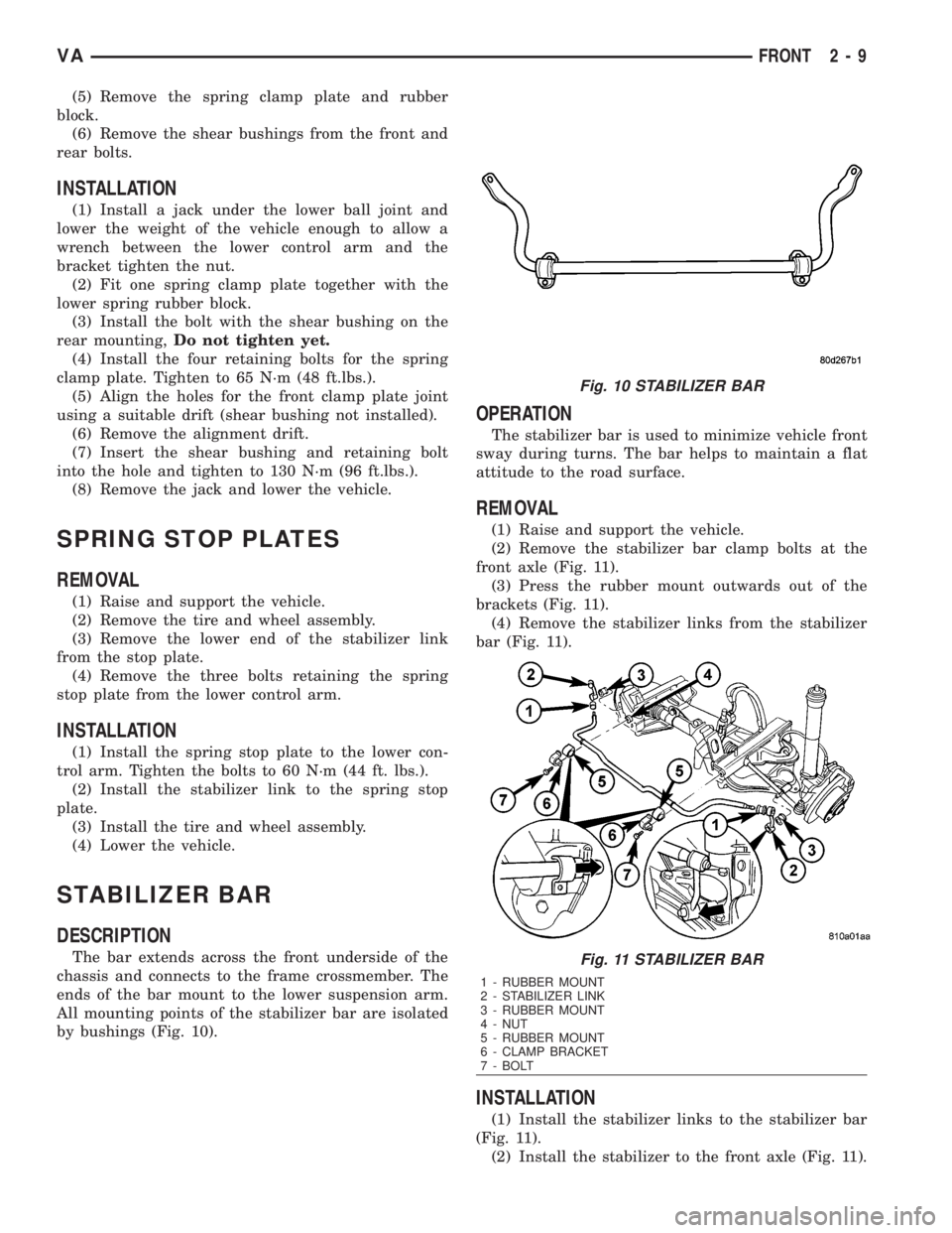
The bar extends across the front underside of the
chassis and connects to the frame crossmember. The
ends of the bar mount to the lower suspension arm.
All mounting points of the stabilizer bar are isolated
by bushings (Fig. 10).
OPERATION
The stabilizer bar is used to minimize vehicle front
sway during turns. The bar helps to maintain a flat
attitude to the road surface.
REMOVAL
(1) Raise and support the vehicle.
(2) Remove the stabilizer bar clamp bolts at the
front axle (Fig. 11).
(3) Press the rubber mount outwards out of the
brackets (Fig. 11).
(4) Remove the stabilizer links from the stabilizer
bar (Fig. 11).
INSTALLATION
(1) Install the stabilizer links to the stabilizer bar
(Fig. 11).
(2) Install the stabilizer to the front axle (Fig. 11).
Fig. 10 STABILIZER BAR
Fig. 11 STABILIZER BAR
1 - RUBBER MOUNT
2 - STABILIZER LINK
3 - RUBBER MOUNT
4 - NUT
5 - RUBBER MOUNT
6 - CLAMP BRACKET
7 - BOLT
VAFRONT 2 - 9
Page 742 of 2305
WHEEL ALIGNMENT
TABLE OF CONTENTS
page page
WHEEL ALIGNMENT
DESCRIPTION........................17
DIAGNOSIS AND TESTING - PRE-ALIGNMENT
INSPECTION.........................17STANDARD PROCEDURE - TOE
ADJUSTMENT........................18
SPECIFICATIONS.....................19
WHEEL ALIGNMENT
DESCRIPTION
NOTE: Camber and Caster are not adjustable on
this vehicle. (TOE ONLY).
NOTE: Suspension components with rubber/ure-
thane bushings should be tightened with the vehi-
cle at normal ride height. It is important to have the
springs supporting the weight of the vehicle when
the fasteners are torqued. If springs are not at their
normal ride position, vehicle ride comfort could be
affected and premature bushing wear may occur.
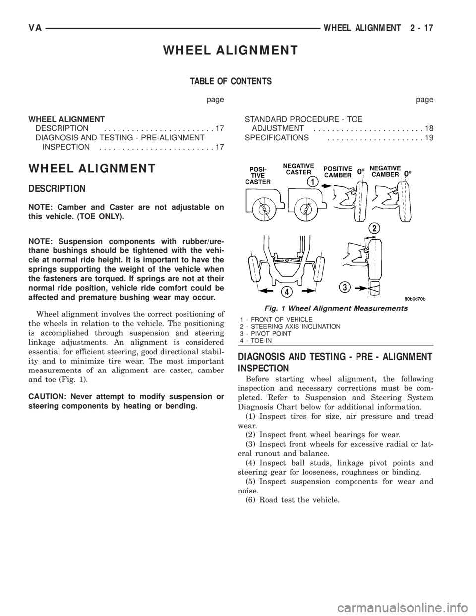
Wheel alignment involves the correct positioning of
the wheels in relation to the vehicle. The positioning
is accomplished through suspension and steering
linkage adjustments. An alignment is considered
essential for efficient steering, good directional stabil-
ity and to minimize tire wear. The most important
measurements of an alignment are caster, camber
and toe (Fig. 1).
CAUTION: Never attempt to modify suspension or
steering components by heating or bending.
DIAGNOSIS AND TESTING - PRE - ALIGNMENT
INSPECTION
Before starting wheel alignment, the following
inspection and necessary corrections must be com-
pleted. Refer to Suspension and Steering System
Diagnosis Chart below for additional information.
(1) Inspect tires for size, air pressure and tread
wear.
(2) Inspect front wheel bearings for wear.
(3) Inspect front wheels for excessive radial or lat-
eral runout and balance.
(4) Inspect ball studs, linkage pivot points and
steering gear for looseness, roughness or binding.
(5) Inspect suspension components for wear and
noise.
(6) Road test the vehicle.
Fig. 1 Wheel Alignment Measurements
1 - FRONT OF VEHICLE
2 - STEERING AXIS INCLINATION
3 - PIVOT POINT
4 - TOE-IN
VAWHEEL ALIGNMENT 2 - 17
Page 743 of 2305
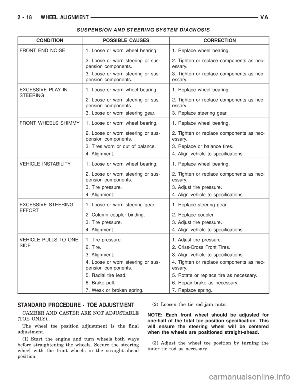
SUSPENSION AND STEERING SYSTEM DIAGNOSIS
CONDITION POSSIBLE CAUSES CORRECTION
FRONT END NOISE 1. Loose or worn wheel bearing. 1. Replace wheel bearing.
2. Loose or worn steering or sus-
pension components.2. Tighten or replace components as nec-
essary.
3. Loose or worn steering or sus-
pension components.3. Tighten or replace components as nec-
essary.
EXCESSIVE PLAY IN
STEERING1. Loose or worn wheel bearing. 1. Replace wheel bearing.
2. Loose or worn steering or sus-
pension components.2. Tighten or replace components as nec-
essary.
3. Loose or worn steering gear. 3. Replace steering gear.
FRONT WHEELS SHIMMY 1. Loose or worn wheel bearing. 1. Replace wheel bearing.
2. Loose or worn steering or sus-
pension components.2. Tighten or replace components as nec-
essary.
3. Tires worn or out of balance. 3. Replace or balance tires.
4. Alignment. 4. Align vehicle to specifications.
VEHICLE INSTABILITY 1. Loose or worn wheel bearing. 1. Replace wheel bearing.
2. Loose or worn steering or sus-
pension components.2. Tighten or replace components as nec-
essary.
3. Tire pressure. 3. Adjust tire pressure.
4. Alignment. 4. Align vehicle to specifications.
EXCESSIVE STEERING
EFFORT1. Loose or worn steering gear. 1. Replace steering gear.
2. Column coupler binding. 2. Replace coupler.
3. Tire pressure. 3. Adjust tire pressure.
4. Alignment. 4. Align vehicle to specifications.
VEHICLE PULLS TO ONE
SIDE1. Tire pressure. 1. Adjust tire pressure.
2. Tire. 2. Criss-Cross Front Tires.
3. Alignment. 3. Align vehicle to specifications.
4. Loose or worn steering or sus-
pension components.4. Tighten or replace components as nec-
essary.
5. Radial tire lead. 5. Rotate or replace tire as necessary.
6. Brake pull. 6. Repair brake as necessary.
7. Weak or broken spring. 7. Replace spring.
STANDARD PROCEDURE - TOE ADJUSTMENT
CAMBER AND CASTER ARE NOT ADJUSTABLE
(TOE ONLY)..
The wheel toe position adjustment is the final
adjustment.
(1) Start the engine and turn wheels both ways
before straightening the wheels. Secure the steering
wheel with the front wheels in the straight-ahead
position.(2) Loosen the tie rod jam nuts.
NOTE: Each front wheel should be adjusted for
one-half of the total toe position specification. This
will ensure the steering wheel will be centered
when the wheels are positioned straight-ahead.
(3) Adjust the wheel toe position by turning the
inner tie rod as necessary.
2 - 18 WHEEL ALIGNMENTVA
Page 744 of 2305
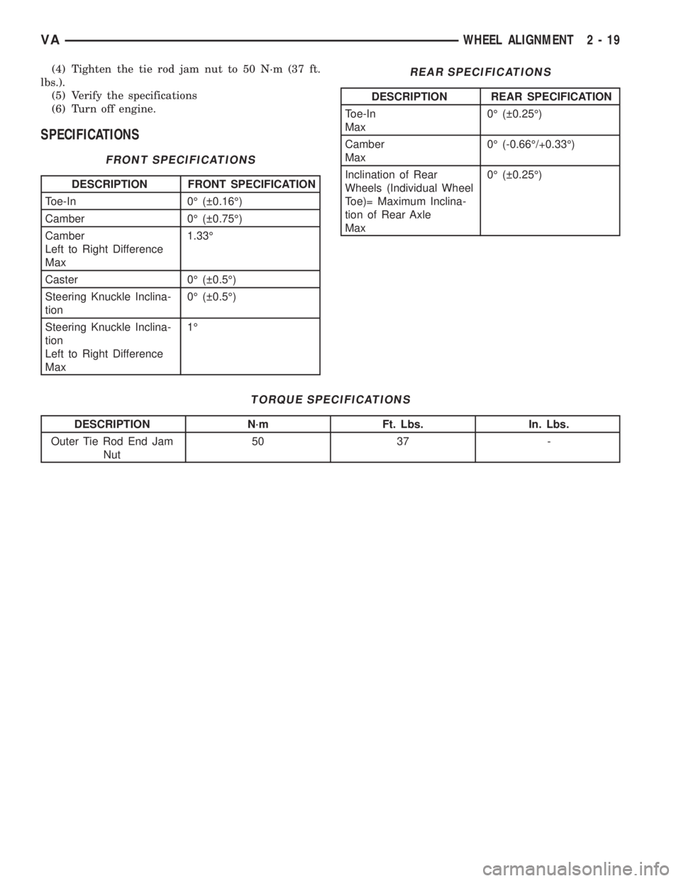
(4) Tighten the tie rod jam nut to 50 N´m (37 ft.
lbs.).
(5) Verify the specifications
(6) Turn off engine.
SPECIFICATIONS
FRONT SPECIFICATIONS
DESCRIPTION FRONT SPECIFICATION
Toe-In 0É ( 0.16É)
Camber 0É ( 0.75É)
Camber
Left to Right Difference
Max1.33É
Caster 0É ( 0.5É)
Steering Knuckle Inclina-
tion0É ( 0.5É)
Steering Knuckle Inclina-
tion
Left to Right Difference
Max1É
REAR SPECIFICATIONS
DESCRIPTION REAR SPECIFICATION
Toe-In
Max0É ( 0.25É)
Camber
Max0É (-0.66É/+0.33É)
Inclination of Rear
Wheels (Individual Wheel
Toe)= Maximum Inclina-
tion of Rear Axle
Max0É ( 0.25É)
TORQUE SPECIFICATIONS
DESCRIPTION N´m Ft. Lbs. In. Lbs.
Outer Tie Rod End Jam
Nut50 37 -
VAWHEEL ALIGNMENT 2 - 19