2006 MERCEDES-BENZ SPRINTER airbag
[x] Cancel search: airbagPage 1049 of 2305
DIAGNOSIS AND TESTING - WIPER &
WASHER SYSTEM
If the wiper motor operates, but the wipers do not
move on the windshield, replace the faulty wiper
linkage module. If the washer pump/motor operates,
but no washer fluid is dispensed on the glass; or, if
the wipers operate, but chatter, lift, or do not clear
the glass, clean and inspect the wiper and washer
system components as required. (Refer to 8 - ELEC-
TRICAL/WIPERS/WASHERS - CLEANING) and
(Refer to 8 - ELECTRICAL/WIPERS/WASHERS -
INSPECTION). For diagnosis and testing of the
multi-function switch (Refer to 8 - ELECTRICAL/
LAMPS/LIGHTING - EXTERIOR/MULTI-FUNC-
TION SWITCH - DIAGNOSIS AND TESTING).
Refer to the appropriate wiring information. The wir-
ing information includes wiring diagrams, proper
wire and connector repair procedures, details of wire
harness routing and retention, connector pin-out
information and location views for the various wire
harness connectors, splices and grounds.
The hard wired circuits and components of the
wiper and washer system may be diagnosed andtested using conventional diagnostic tools and proce-
dures. However, conventional diagnostic methods
may not prove conclusive in the diagnosis of the
intermittent wipe logic circuitry contained within the
fuse block underneath the steering column, the rain
sensor within the base of the rear view mirror on the
windshield, or the rain sensor control module under
the instrument panel.
WARNING: To avoid personal injury or death, on
vehicles equipped with airbags, disable the supple-
mental restraint system before attempting any
steering wheel, steering column, airbag, seat belt
tensioner, or instrument panel component diagno-
sis or service. Disconnect and isolate the battery
negative (ground) cable, then wait two minutes for
the system capacitor to discharge before perform-
ing further diagnosis or service. This is the only
sure way to disable the supplemental restraint sys-
tem. Failure to take the proper precautions could
result in accidental airbag deployment.
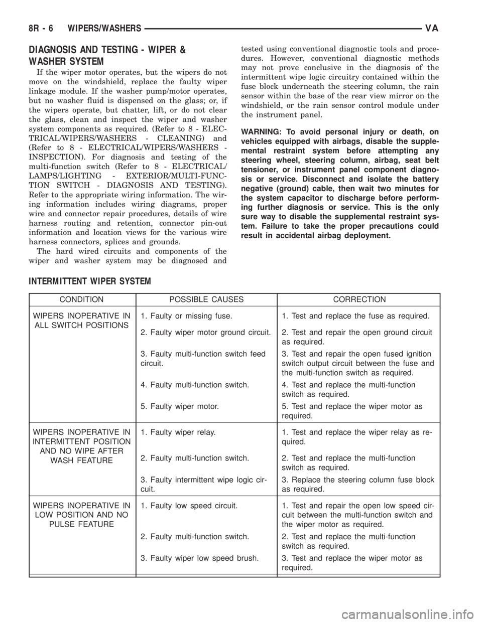
INTERMITTENT WIPER SYSTEM
CONDITION POSSIBLE CAUSES CORRECTION
WIPERS INOPERATIVE IN
ALL SWITCH POSITIONS1. Faulty or missing fuse. 1. Test and replace the fuse as required.
2. Faulty wiper motor ground circuit. 2. Test and repair the open ground circuit
as required.
3. Faulty multi-function switch feed
circuit.3. Test and repair the open fused ignition
switch output circuit between the fuse and
the multi-function switch as required.
4. Faulty multi-function switch. 4. Test and replace the multi-function
switch as required.
5. Faulty wiper motor. 5. Test and replace the wiper motor as
required.
WIPERS INOPERATIVE IN
INTERMITTENT POSITION
AND NO WIPE AFTER
WASH FEATURE1. Faulty wiper relay. 1. Test and replace the wiper relay as re-
quired.
2. Faulty multi-function switch. 2. Test and replace the multi-function
switch as required.
3. Faulty intermittent wipe logic cir-
cuit.3. Replace the steering column fuse block
as required.
WIPERS INOPERATIVE IN
LOW POSITION AND NO
PULSE FEATURE1. Faulty low speed circuit. 1. Test and repair the open low speed cir-
cuit between the multi-function switch and
the wiper motor as required.
2. Faulty multi-function switch. 2. Test and replace the multi-function
switch as required.
3. Faulty wiper low speed brush. 3. Test and replace the wiper motor as
required.
8R - 6 WIPERS/WASHERSVA
Page 1056 of 2305
WARNING: To avoid personal injury or death, on
vehicles equipped with airbags, disable the supple-
mental restraint system before attempting any
steering wheel, steering column, airbag, seat belt
tensioner, or instrument panel component diagno-
sis or service. Disconnect and isolate the battery
negative (ground) cable, then wait two minutes for
the system capacitor to discharge before perform-
ing further diagnosis or service. This is the only
sure way to disable the supplemental restraint sys-
tem. Failure to take the proper precautions could
result in accidental airbag deployment.
CAUTION: Do not touch the gel-like surface of the
rain sensor or the sensor function may be impaired
and the sensor rendered unusable.
(1) Disconnect and isolate the battery negative
cable.
(2) Remove the rear view mirror and the rain sen-
sor from the rain sensor bracket. (Refer to 8 - ELEC-
TRICAL/WIPERS/WASHERS/RAIN SENSOR -
REMOVAL).
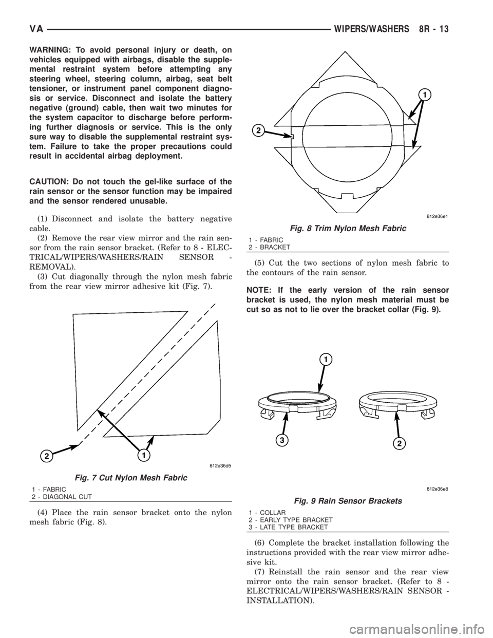
(3) Cut diagonally through the nylon mesh fabric
from the rear view mirror adhesive kit (Fig. 7).
(4) Place the rain sensor bracket onto the nylon
mesh fabric (Fig. 8).(5) Cut the two sections of nylon mesh fabric to
the contours of the rain sensor.
NOTE: If the early version of the rain sensor
bracket is used, the nylon mesh material must be
cut so as not to lie over the bracket collar (Fig. 9).
(6) Complete the bracket installation following the
instructions provided with the rear view mirror adhe-
sive kit.
(7) Reinstall the rain sensor and the rear view
mirror onto the rain sensor bracket. (Refer to 8 -
ELECTRICAL/WIPERS/WASHERS/RAIN SENSOR -
INSTALLATION).
Fig. 7 Cut Nylon Mesh Fabric
1 - FABRIC
2 - DIAGONAL CUT
Fig. 8 Trim Nylon Mesh Fabric
1 - FABRIC
2 - BRACKET
Fig. 9 Rain Sensor Brackets
1 - COLLAR
2 - EARLY TYPE BRACKET
3 - LATE TYPE BRACKET
VAWIPERS/WASHERS 8R - 13
Page 1057 of 2305
(8) Reconnect the battery negative cable.
REMOVAL
WARNING: To avoid personal injury or death, on
vehicles equipped with airbags, disable the supple-
mental restraint system before attempting any
steering wheel, steering column, airbag, seat belt
tensioner, or instrument panel component diagno-
sis or service. Disconnect and isolate the battery
negative (ground) cable, then wait two minutes for
the system capacitor to discharge before perform-
ing further diagnosis or service. This is the only
sure way to disable the supplemental restraint sys-
tem. Failure to take the proper precautions could
result in accidental airbag deployment.
(1) Disconnect and isolate the battery negative
cable.
(2) Unsnap the base covers from each other and
remove them from the rear view mirror arm at the
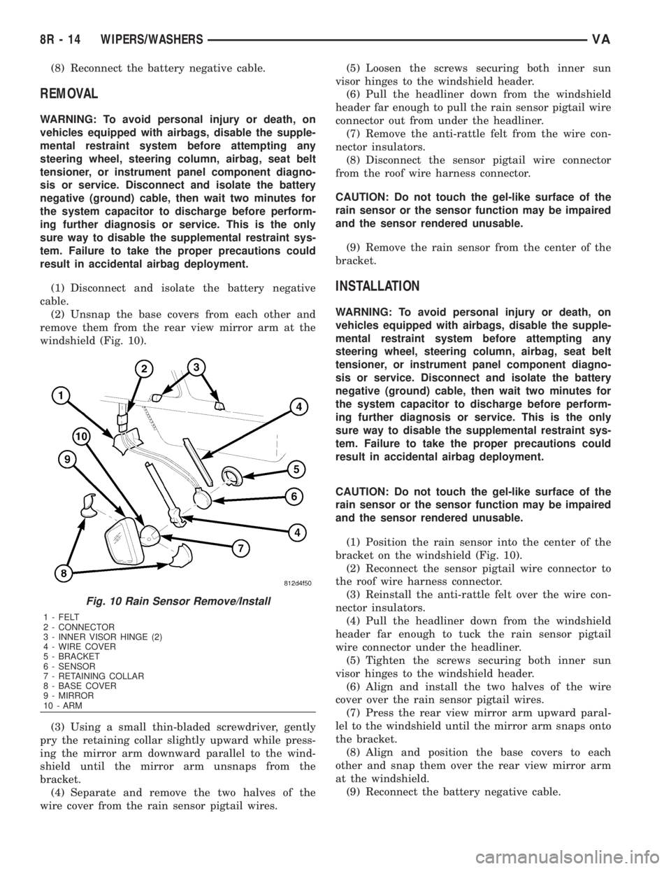
windshield (Fig. 10).
(3) Using a small thin-bladed screwdriver, gently
pry the retaining collar slightly upward while press-
ing the mirror arm downward parallel to the wind-
shield until the mirror arm unsnaps from the
bracket.
(4) Separate and remove the two halves of the
wire cover from the rain sensor pigtail wires.(5) Loosen the screws securing both inner sun
visor hinges to the windshield header.
(6) Pull the headliner down from the windshield
header far enough to pull the rain sensor pigtail wire
connector out from under the headliner.
(7) Remove the anti-rattle felt from the wire con-
nector insulators.
(8) Disconnect the sensor pigtail wire connector
from the roof wire harness connector.
CAUTION: Do not touch the gel-like surface of the
rain sensor or the sensor function may be impaired
and the sensor rendered unusable.
(9) Remove the rain sensor from the center of the
bracket.
INSTALLATION
WARNING: To avoid personal injury or death, on
vehicles equipped with airbags, disable the supple-
mental restraint system before attempting any
steering wheel, steering column, airbag, seat belt
tensioner, or instrument panel component diagno-
sis or service. Disconnect and isolate the battery
negative (ground) cable, then wait two minutes for
the system capacitor to discharge before perform-
ing further diagnosis or service. This is the only
sure way to disable the supplemental restraint sys-
tem. Failure to take the proper precautions could
result in accidental airbag deployment.
CAUTION: Do not touch the gel-like surface of the
rain sensor or the sensor function may be impaired
and the sensor rendered unusable.
(1) Position the rain sensor into the center of the
bracket on the windshield (Fig. 10).
(2) Reconnect the sensor pigtail wire connector to
the roof wire harness connector.
(3) Reinstall the anti-rattle felt over the wire con-
nector insulators.
(4) Pull the headliner down from the windshield
header far enough to tuck the rain sensor pigtail
wire connector under the headliner.
(5) Tighten the screws securing both inner sun
visor hinges to the windshield header.
(6) Align and install the two halves of the wire
cover over the rain sensor pigtail wires.
(7) Press the rear view mirror arm upward paral-
lel to the windshield until the mirror arm snaps onto
the bracket.
(8) Align and position the base covers to each
other and snap them over the rear view mirror arm
at the windshield.
(9) Reconnect the battery negative cable.
Fig. 10 Rain Sensor Remove/Install
1 - FELT
2 - CONNECTOR
3 - INNER VISOR HINGE (2)
4 - WIRE COVER
5 - BRACKET
6 - SENSOR
7 - RETAINING COLLAR
8 - BASE COVER
9 - MIRROR
10 - ARM
8R - 14 WIPERS/WASHERSVA
Page 1058 of 2305
RAIN SENSOR CONTROL MOD-
ULE
DESCRIPTION
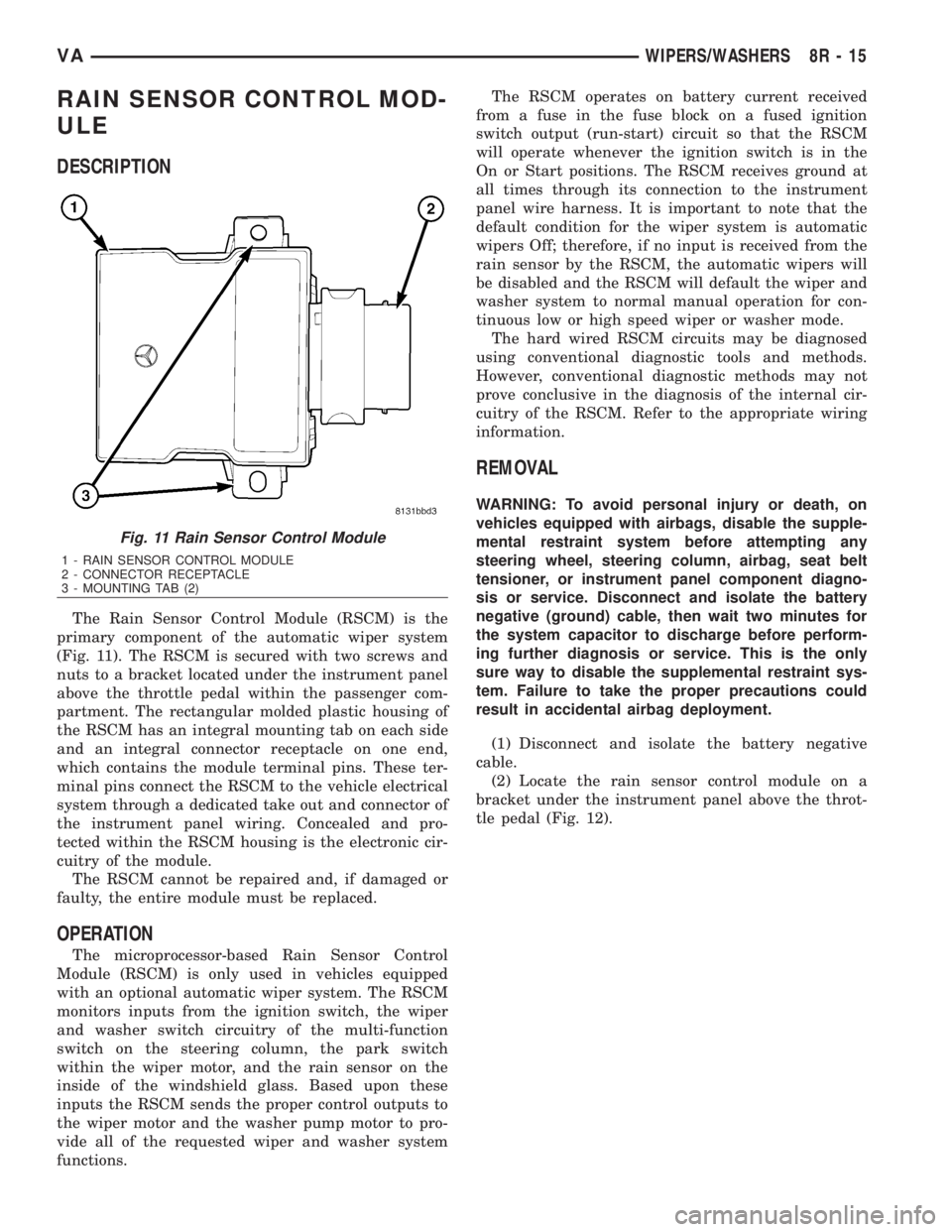
The Rain Sensor Control Module (RSCM) is the
primary component of the automatic wiper system
(Fig. 11). The RSCM is secured with two screws and
nuts to a bracket located under the instrument panel
above the throttle pedal within the passenger com-
partment. The rectangular molded plastic housing of
the RSCM has an integral mounting tab on each side
and an integral connector receptacle on one end,
which contains the module terminal pins. These ter-
minal pins connect the RSCM to the vehicle electrical
system through a dedicated take out and connector of
the instrument panel wiring. Concealed and pro-
tected within the RSCM housing is the electronic cir-
cuitry of the module.
The RSCM cannot be repaired and, if damaged or
faulty, the entire module must be replaced.
OPERATION
The microprocessor-based Rain Sensor Control
Module (RSCM) is only used in vehicles equipped
with an optional automatic wiper system. The RSCM
monitors inputs from the ignition switch, the wiper
and washer switch circuitry of the multi-function
switch on the steering column, the park switch
within the wiper motor, and the rain sensor on the
inside of the windshield glass. Based upon these
inputs the RSCM sends the proper control outputs to
the wiper motor and the washer pump motor to pro-
vide all of the requested wiper and washer system
functions.The RSCM operates on battery current received
from a fuse in the fuse block on a fused ignition
switch output (run-start) circuit so that the RSCM
will operate whenever the ignition switch is in the
On or Start positions. The RSCM receives ground at
all times through its connection to the instrument
panel wire harness. It is important to note that the
default condition for the wiper system is automatic
wipers Off; therefore, if no input is received from the
rain sensor by the RSCM, the automatic wipers will
be disabled and the RSCM will default the wiper and
washer system to normal manual operation for con-
tinuous low or high speed wiper or washer mode.
The hard wired RSCM circuits may be diagnosed
using conventional diagnostic tools and methods.
However, conventional diagnostic methods may not
prove conclusive in the diagnosis of the internal cir-
cuitry of the RSCM. Refer to the appropriate wiring
information.
REMOVAL
WARNING: To avoid personal injury or death, on
vehicles equipped with airbags, disable the supple-
mental restraint system before attempting any
steering wheel, steering column, airbag, seat belt
tensioner, or instrument panel component diagno-
sis or service. Disconnect and isolate the battery
negative (ground) cable, then wait two minutes for
the system capacitor to discharge before perform-
ing further diagnosis or service. This is the only
sure way to disable the supplemental restraint sys-
tem. Failure to take the proper precautions could
result in accidental airbag deployment.
(1) Disconnect and isolate the battery negative
cable.
(2) Locate the rain sensor control module on a
bracket under the instrument panel above the throt-
tle pedal (Fig. 12).
Fig. 11 Rain Sensor Control Module
1 - RAIN SENSOR CONTROL MODULE
2 - CONNECTOR RECEPTACLE
3 - MOUNTING TAB (2)
VAWIPERS/WASHERS 8R - 15
Page 1059 of 2305
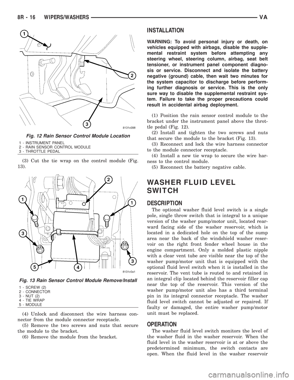
(3) Cut the tie wrap on the control module (Fig.
13).
(4) Unlock and disconnect the wire harness con-
nector from the module connector receptacle.
(5) Remove the two screws and nuts that secure
the module to the bracket.
(6) Remove the module from the bracket.
INSTALLATION
WARNING: To avoid personal injury or death, on
vehicles equipped with airbags, disable the supple-
mental restraint system before attempting any
steering wheel, steering column, airbag, seat belt
tensioner, or instrument panel component diagno-
sis or service. Disconnect and isolate the battery
negative (ground) cable, then wait two minutes for
the system capacitor to discharge before perform-
ing further diagnosis or service. This is the only
sure way to disable the supplemental restraint sys-
tem. Failure to take the proper precautions could
result in accidental airbag deployment.
(1) Position the rain sensor control module to the
bracket under the instrument panel above the throt-
tle pedal (Fig. 12).
(2) Install and tighten the two screws and nuts
that secure the module to the bracket (Fig. 13).
(3) Reconnect and lock the wire harness connector
to the module connector receptacle.
(4) Install a new tie wrap to secure the wire har-
ness to the control module.
(5) Reconnect the battery negative cable.
WASHER FLUID LEVEL
SWITCH
DESCRIPTION
The optional washer fluid level switch is a single
pole, single throw switch that is integral to a unique
version of the washer pump/motor unit, located rear-
ward facing side of the washer reservoir, which is
located in a dedicated hole on the top of the sump
area near the back of the windshield washer reser-
voir on the right front fender wheel house in the
engine compartment. Only a molded plastic nipple
with a clear vent tube are visible near the top of the
washer pump/motor unit that is equipped with the
optional fluid level switch when it is installed in the
reservoir. The vent tube is routed to and retained in
an integral clip located behind the reservoir filler cap
near the top of the reservoir. This version of the
washer pump/motor unit also has a third terminal
pin in its integral connector receptacle. The washer
fluid level switch cannot be adjusted or repaired. If
faulty or damaged, the entire washer pump/motor
unit must be replaced.
OPERATION
The washer fluid level switch monitors the level of
the washer fluid in the washer reservoir. When the
fluid level in the washer reservoir is at or above the
predetermined minimum, the switch contacts are
open. When the fluid level in the washer reservoir
Fig. 12 Rain Sensor Control Module Location
1 - INSTRUMENT PANEL
2 - RAIN SENSOR CONTROL MODULE
3 - THROTTLE PEDAL
Fig. 13 Rain Sensor Control Module Remove/Install
1 - SCREW (2)
2 - CONNECTOR
3 - NUT (2)
4 - TIE WRAP
5 - MODULE
8R - 16 WIPERS/WASHERSVA
Page 1078 of 2305
²The normally closed terminal (87A) is connected
to battery current through a fused ignition switch
output circuit whenever the ignition switch is in the
On position.
The wiper relay can be diagnosed using conven-
tional diagnostic tools and methods.
REMOVAL
WARNING: To avoid personal injury or death, on
vehicles equipped with airbags, disable the supple-
mental restraint system before attempting any
steering wheel, steering column, airbag, seat belt
tensioner, or instrument panel component diagno-
sis or service. Disconnect and isolate the battery
negative (ground) cable, then wait two minutes for
the system capacitor to discharge before perform-
ing further diagnosis or service. This is the only
sure way to disable the supplemental restraint sys-
tem. Failure to take the proper precautions could
result in accidental airbag deployment.
(1) Disconnect and isolate the battery negative
cable.
(2) Remove the fuse access panel from the steering
column opening cover below the steering column on
the instrument panel.
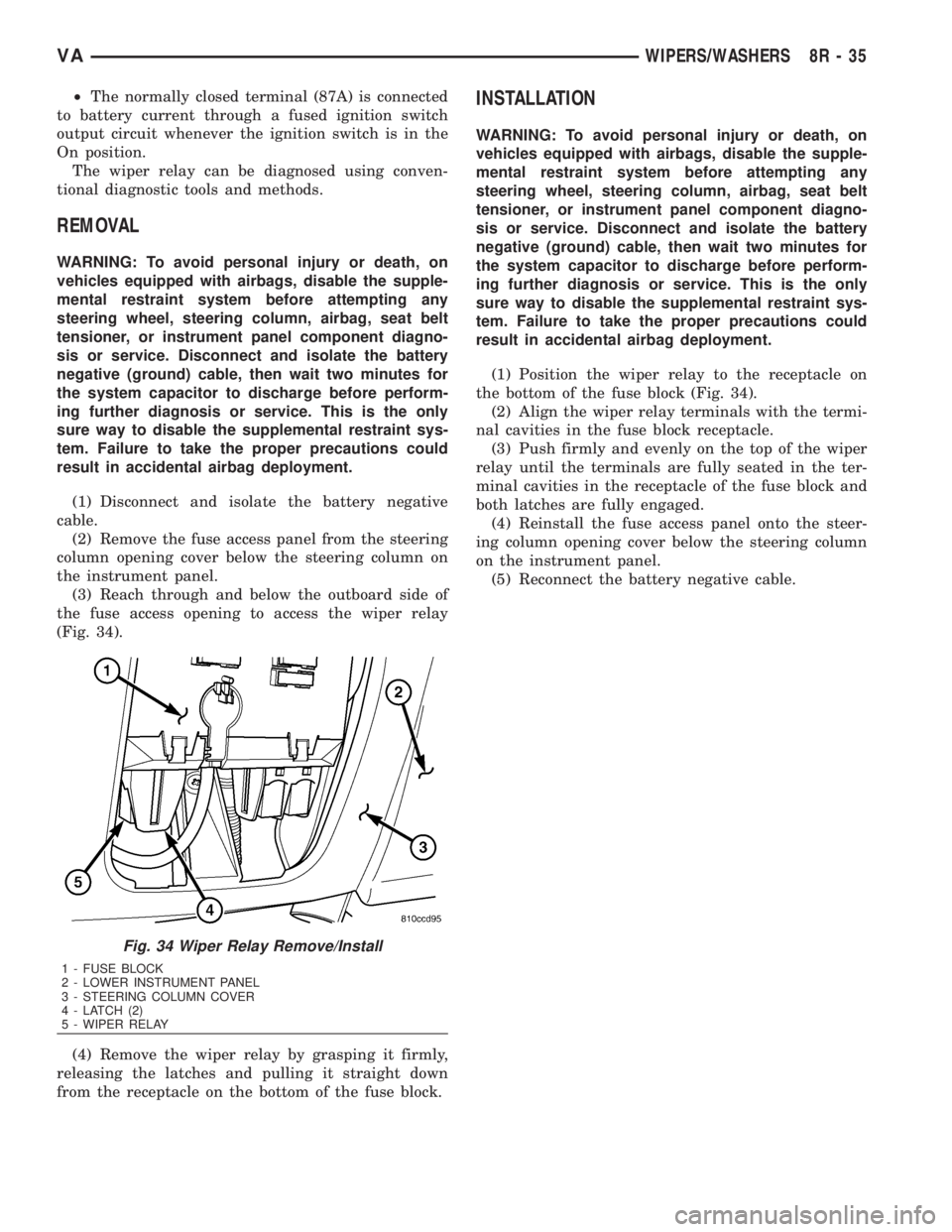
(3) Reach through and below the outboard side of
the fuse access opening to access the wiper relay
(Fig. 34).
(4) Remove the wiper relay by grasping it firmly,
releasing the latches and pulling it straight down
from the receptacle on the bottom of the fuse block.
INSTALLATION
WARNING: To avoid personal injury or death, on
vehicles equipped with airbags, disable the supple-
mental restraint system before attempting any
steering wheel, steering column, airbag, seat belt
tensioner, or instrument panel component diagno-
sis or service. Disconnect and isolate the battery
negative (ground) cable, then wait two minutes for
the system capacitor to discharge before perform-
ing further diagnosis or service. This is the only
sure way to disable the supplemental restraint sys-
tem. Failure to take the proper precautions could
result in accidental airbag deployment.
(1) Position the wiper relay to the receptacle on
the bottom of the fuse block (Fig. 34).
(2) Align the wiper relay terminals with the termi-
nal cavities in the fuse block receptacle.
(3) Push firmly and evenly on the top of the wiper
relay until the terminals are fully seated in the ter-
minal cavities in the receptacle of the fuse block and
both latches are fully engaged.
(4) Reinstall the fuse access panel onto the steer-
ing column opening cover below the steering column
on the instrument panel.
(5) Reconnect the battery negative cable.
Fig. 34 Wiper Relay Remove/Install
1 - FUSE BLOCK
2 - LOWER INSTRUMENT PANEL
3 - STEERING COLUMN COVER
4 - LATCH (2)
5 - WIPER RELAY
VAWIPERS/WASHERS 8R - 35
Page 1080 of 2305
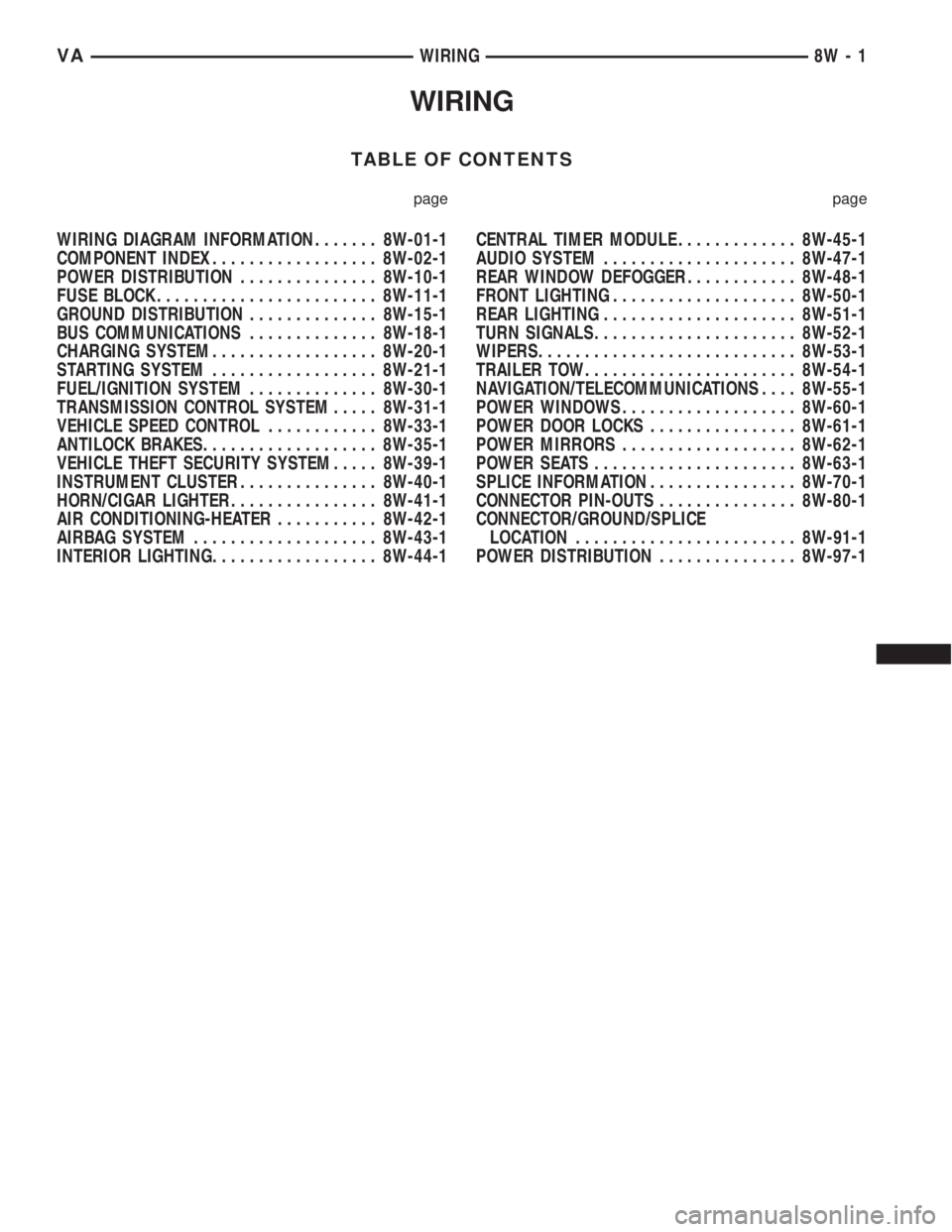
WIRING
TABLE OF CONTENTS
page page
WIRING DIAGRAM INFORMATION....... 8W-01-1
COMPONENT INDEX.................. 8W-02-1
POWER DISTRIBUTION............... 8W-10-1
FUSE BLOCK........................ 8W-11-1
GROUND DISTRIBUTION.............. 8W-15-1
BUS COMMUNICATIONS.............. 8W-18-1
CHARGING SYSTEM.................. 8W-20-1
STARTING SYSTEM.................. 8W-21-1
FUEL/IGNITION SYSTEM.............. 8W-30-1
TRANSMISSION CONTROL SYSTEM..... 8W-31-1
VEHICLE SPEED CONTROL............ 8W-33-1
ANTILOCK BRAKES................... 8W-35-1
VEHICLE THEFT SECURITY SYSTEM..... 8W-39-1
INSTRUMENT CLUSTER............... 8W-40-1
HORN/CIGAR LIGHTER................ 8W-41-1
AIR CONDITIONING-HEATER........... 8W-42-1
AIRBAG SYSTEM.................... 8W-43-1
INTERIOR LIGHTING.................. 8W-44-1CENTRAL TIMER MODULE............. 8W-45-1
AUDIO SYSTEM..................... 8W-47-1
REAR WINDOW DEFOGGER............ 8W-48-1
FRONT LIGHTING.................... 8W-50-1
REAR LIGHTING..................... 8W-51-1
TURN SIGNALS...................... 8W-52-1
WIPERS............................ 8W-53-1
TRAILER TOW....................... 8W-54-1
NAVIGATION/TELECOMMUNICATIONS.... 8W-55-1
POWER WINDOWS................... 8W-60-1
POWER DOOR LOCKS................ 8W-61-1
POWER MIRRORS................... 8W-62-1
POWER SEATS...................... 8W-63-1
SPLICE INFORMATION................ 8W-70-1
CONNECTOR PIN-OUTS............... 8W-80-1
CONNECTOR/GROUND/SPLICE
LOCATION........................ 8W-91-1
POWER DISTRIBUTION............... 8W-97-1 VAWIRING 8W - 1
Page 1092 of 2305
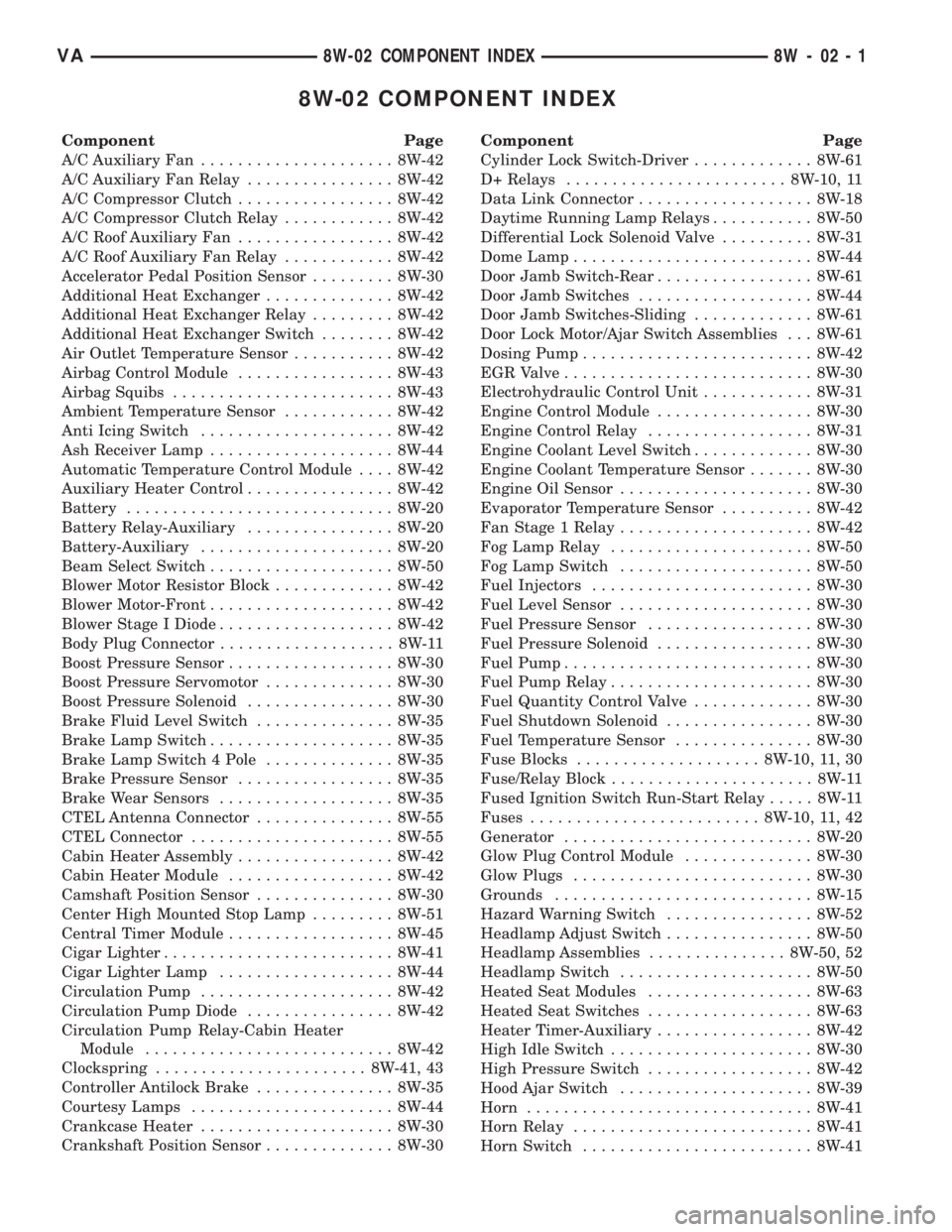
8W-02 COMPONENT INDEX
Component Page
A/C Auxiliary Fan..................... 8W-42
A/C Auxiliary Fan Relay................ 8W-42
A/C Compressor Clutch................. 8W-42
A/C Compressor Clutch Relay............ 8W-42
A/C Roof Auxiliary Fan................. 8W-42
A/C Roof Auxiliary Fan Relay............ 8W-42
Accelerator Pedal Position Sensor......... 8W-30
Additional Heat Exchanger.............. 8W-42
Additional Heat Exchanger Relay......... 8W-42
Additional Heat Exchanger Switch........ 8W-42
Air Outlet Temperature Sensor........... 8W-42
Airbag Control Module................. 8W-43
Airbag Squibs........................ 8W-43
Ambient Temperature Sensor............ 8W-42
Anti Icing Switch..................... 8W-42
Ash Receiver Lamp.................... 8W-44
Automatic Temperature Control Module.... 8W-42
Auxiliary Heater Control................ 8W-42
Battery............................. 8W-20
Battery Relay-Auxiliary................ 8W-20
Battery-Auxiliary..................... 8W-20
Beam Select Switch.................... 8W-50
Blower Motor Resistor Block............. 8W-42
Blower Motor-Front.................... 8W-42
Blower Stage I Diode................... 8W-42
Body Plug Connector................... 8W-11
Boost Pressure Sensor.................. 8W-30
Boost Pressure Servomotor.............. 8W-30
Boost Pressure Solenoid................ 8W-30
Brake Fluid Level Switch............... 8W-35
Brake Lamp Switch.................... 8W-35
Brake Lamp Switch 4 Pole.............. 8W-35
Brake Pressure Sensor................. 8W-35
Brake Wear Sensors................... 8W-35
CTEL Antenna Connector............... 8W-55
CTEL Connector...................... 8W-55
Cabin Heater Assembly................. 8W-42
Cabin Heater Module.................. 8W-42
Camshaft Position Sensor............... 8W-30
Center High Mounted Stop Lamp......... 8W-51
Central Timer Module.................. 8W-45
Cigar Lighter......................... 8W-41
Cigar Lighter Lamp................... 8W-44
Circulation Pump..................... 8W-42
Circulation Pump Diode................ 8W-42
Circulation Pump Relay-Cabin Heater
Module........................... 8W-42
Clockspring....................... 8W-41, 43
Controller Antilock Brake............... 8W-35
Courtesy Lamps...................... 8W-44
Crankcase Heater..................... 8W-30
Crankshaft Position Sensor.............. 8W-30Component Page
Cylinder Lock Switch-Driver............. 8W-61
D+ Relays........................ 8W-10, 11
Data Link Connector................... 8W-18
Daytime Running Lamp Relays........... 8W-50
Differential Lock Solenoid Valve.......... 8W-31
Dome Lamp.......................... 8W-44
Door Jamb Switch-Rear................. 8W-61
Door Jamb Switches................... 8W-44
Door Jamb Switches-Sliding............. 8W-61
Door Lock Motor/Ajar Switch Assemblies . . . 8W-61
Dosing Pump......................... 8W-42
EGR Valve........................... 8W-30
Electrohydraulic Control Unit............ 8W-31
Engine Control Module................. 8W-30
Engine Control Relay.................. 8W-31
Engine Coolant Level Switch............. 8W-30
Engine Coolant Temperature Sensor....... 8W-30
Engine Oil Sensor..................... 8W-30
Evaporator Temperature Sensor.......... 8W-42
Fan Stage 1 Relay..................... 8W-42
Fog Lamp Relay...................... 8W-50
Fog Lamp Switch..................... 8W-50
Fuel Injectors........................ 8W-30
Fuel Level Sensor..................... 8W-30
Fuel Pressure Sensor.................. 8W-30
Fuel Pressure Solenoid................. 8W-30
Fuel Pump........................... 8W-30
Fuel Pump Relay...................... 8W-30
Fuel Quantity Control Valve............. 8W-30
Fuel Shutdown Solenoid................ 8W-30
Fuel Temperature Sensor............... 8W-30
Fuse Blocks.................... 8W-10, 11, 30
Fuse/Relay Block...................... 8W-11
Fused Ignition Switch Run-Start Relay..... 8W-11
Fuses......................... 8W-10, 11, 42
Generator........................... 8W-20
Glow Plug Control Module.............. 8W-30
Glow Plugs.......................... 8W-30
Grounds............................ 8W-15
Hazard Warning Switch................ 8W-52
Headlamp Adjust Switch................ 8W-50
Headlamp Assemblies............... 8W-50, 52
Headlamp Switch..................... 8W-50
Heated Seat Modules.................. 8W-63
Heated Seat Switches.................. 8W-63
Heater Timer-Auxiliary................. 8W-42
High Idle Switch...................... 8W-30
High Pressure Switch.................. 8W-42
Hood Ajar Switch..................... 8W-39
Horn............................... 8W-41
Horn Relay.......................... 8W-41
Horn Switch......................... 8W-41
VA8W-02 COMPONENT INDEX 8W - 02 - 1