2006 MERCEDES-BENZ SPRINTER engine coolant
[x] Cancel search: engine coolantPage 1586 of 2305
(39) Fill cooling system to proper level with the
appropriate coolant.
(40) Evacuate and recharge air conditioning.
(41) Check and refill all ancillary system fluid lev-
els.(42) Start engine and inspect for leaks (Refer to 14
- FUEL SYSTEM - WARNING).
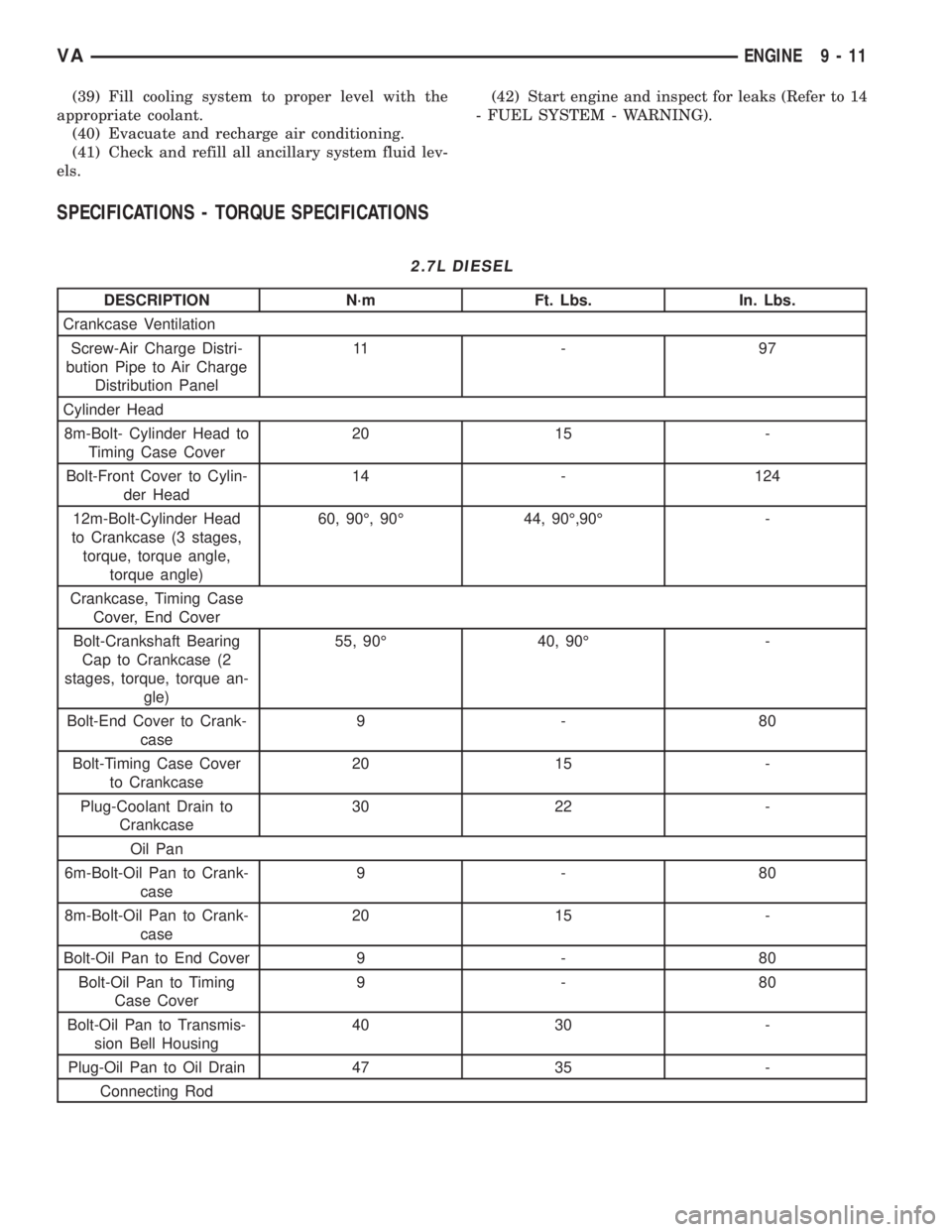
SPECIFICATIONS - TORQUE SPECIFICATIONS
2.7L DIESEL
DESCRIPTION N´m Ft. Lbs. In. Lbs.
Crankcase Ventilation
Screw-Air Charge Distri-
bution Pipe to Air Charge
Distribution Panel11 - 9 7
Cylinder Head
8m-Bolt- Cylinder Head to
Timing Case Cover20 15 -
Bolt-Front Cover to Cylin-
der Head14 - 124
12m-Bolt-Cylinder Head
to Crankcase (3 stages,
torque, torque angle,
torque angle)60, 90É, 90É 44, 90É,90É -
Crankcase, Timing Case
Cover, End Cover
Bolt-Crankshaft Bearing
Cap to Crankcase (2
stages, torque, torque an-
gle)55, 90É 40, 90É -
Bolt-End Cover to Crank-
case9-80
Bolt-Timing Case Cover
to Crankcase20 15 -
Plug-Coolant Drain to
Crankcase30 22 -
Oil Pan
6m-Bolt-Oil Pan to Crank-
case9-80
8m-Bolt-Oil Pan to Crank-
case20 15 -
Bolt-Oil Pan to End Cover 9 - 80
Bolt-Oil Pan to Timing
Case Cover9-80
Bolt-Oil Pan to Transmis-
sion Bell Housing40 30 -
Plug-Oil Pan to Oil Drain 47 35 -
Connecting Rod
VAENGINE 9 - 11
Page 1589 of 2305
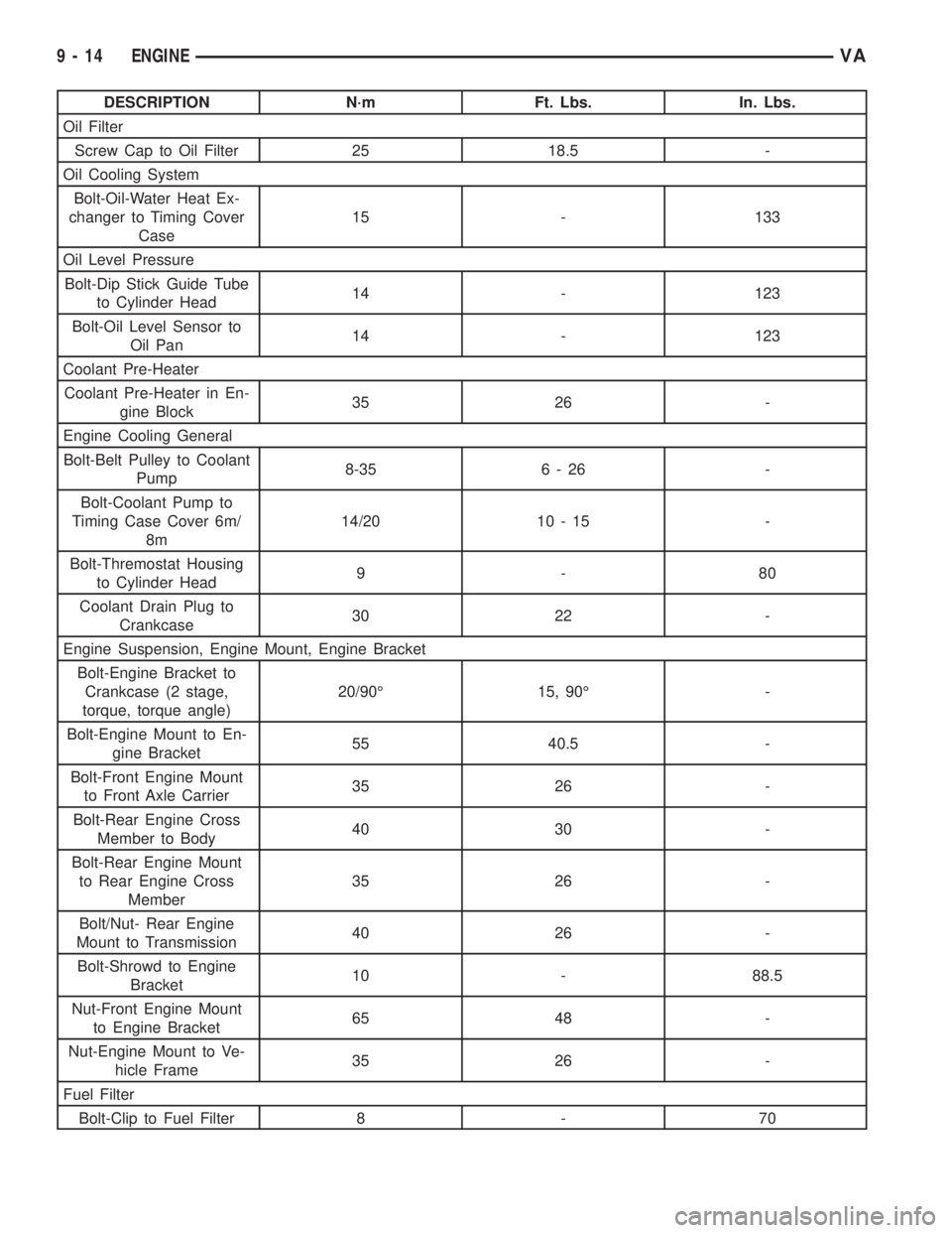
DESCRIPTION N´m Ft. Lbs. In. Lbs.
Oil Filter
Screw Cap to Oil Filter 25 18.5 -
Oil Cooling System
Bolt-Oil-Water Heat Ex-
changer to Timing Cover
Case15 - 133
Oil Level Pressure
Bolt-Dip Stick Guide Tube
to Cylinder Head14 - 123
Bolt-Oil Level Sensor to
Oil Pan14 - 123
Coolant Pre-Heater
Coolant Pre-Heater in En-
gine Block35 26 -
Engine Cooling General
Bolt-Belt Pulley to Coolant
Pump8-35 6 - 26 -
Bolt-Coolant Pump to
Timing Case Cover 6m/
8m14/20 10 - 15 -
Bolt-Thremostat Housing
to Cylinder Head9-80
Coolant Drain Plug to
Crankcase30 22 -
Engine Suspension, Engine Mount, Engine Bracket
Bolt-Engine Bracket to
Crankcase (2 stage,
torque, torque angle)20/90É 15, 90É -
Bolt-Engine Mount to En-
gine Bracket55 40.5 -
Bolt-Front Engine Mount
to Front Axle Carrier35 26 -
Bolt-Rear Engine Cross
Member to Body40 30 -
Bolt-Rear Engine Mount
to Rear Engine Cross
Member35 26 -
Bolt/Nut- Rear Engine
Mount to Transmission40 26 -
Bolt-Shrowd to Engine
Bracket10 - 88.5
Nut-Front Engine Mount
to Engine Bracket65 48 -
Nut-Engine Mount to Ve-
hicle Frame35 26 -
Fuel Filter
Bolt-Clip to Fuel Filter 8 - 70
9 - 14 ENGINEVA
Page 1598 of 2305
NOTE: The camshaft housing Must Not be
machined. Basic bore of the camshaft bearings will
be altered.
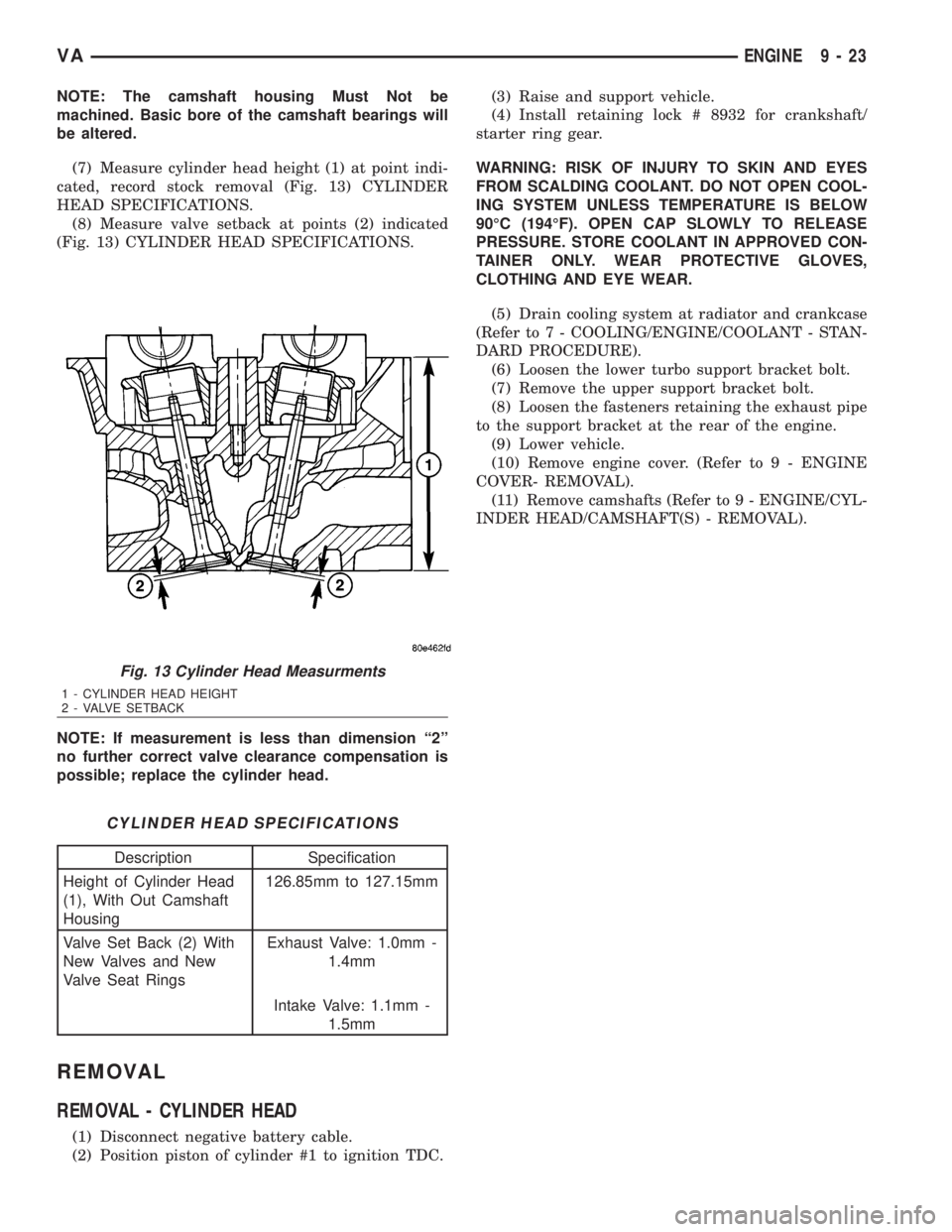
(7) Measure cylinder head height (1) at point indi-
cated, record stock removal (Fig. 13) CYLINDER
HEAD SPECIFICATIONS.
(8) Measure valve setback at points (2) indicated
(Fig. 13) CYLINDER HEAD SPECIFICATIONS.
NOTE: If measurement is less than dimension ª2º
no further correct valve clearance compensation is
possible; replace the cylinder head.
CYLINDER HEAD SPECIFICATIONS
Description Specification
Height of Cylinder Head
(1), With Out Camshaft
Housing126.85mm to 127.15mm
Valve Set Back (2) With
New Valves and New
Valve Seat RingsExhaust Valve: 1.0mm -
1.4mm
Intake Valve: 1.1mm -
1.5mm
REMOVAL
REMOVAL - CYLINDER HEAD
(1) Disconnect negative battery cable.
(2) Position piston of cylinder #1 to ignition TDC.(3) Raise and support vehicle.
(4) Install retaining lock # 8932 for crankshaft/
starter ring gear.
WARNING: RISK OF INJURY TO SKIN AND EYES
FROM SCALDING COOLANT. DO NOT OPEN COOL-
ING SYSTEM UNLESS TEMPERATURE IS BELOW
90ÉC (194ÉF). OPEN CAP SLOWLY TO RELEASE
PRESSURE. STORE COOLANT IN APPROVED CON-
TAINER ONLY. WEAR PROTECTIVE GLOVES,
CLOTHING AND EYE WEAR.
(5) Drain cooling system at radiator and crankcase
(Refer to 7 - COOLING/ENGINE/COOLANT - STAN-
DARD PROCEDURE).
(6) Loosen the lower turbo support bracket bolt.
(7) Remove the upper support bracket bolt.
(8) Loosen the fasteners retaining the exhaust pipe
to the support bracket at the rear of the engine.
(9) Lower vehicle.
(10) Remove engine cover. (Refer to 9 - ENGINE
COVER- REMOVAL).
(11) Remove camshafts (Refer to 9 - ENGINE/CYL-
INDER HEAD/CAMSHAFT(S) - REMOVAL).
Fig. 13 Cylinder Head Measurments
1 - CYLINDER HEAD HEIGHT
2 - VALVE SETBACK
VAENGINE 9 - 23
Page 1599 of 2305
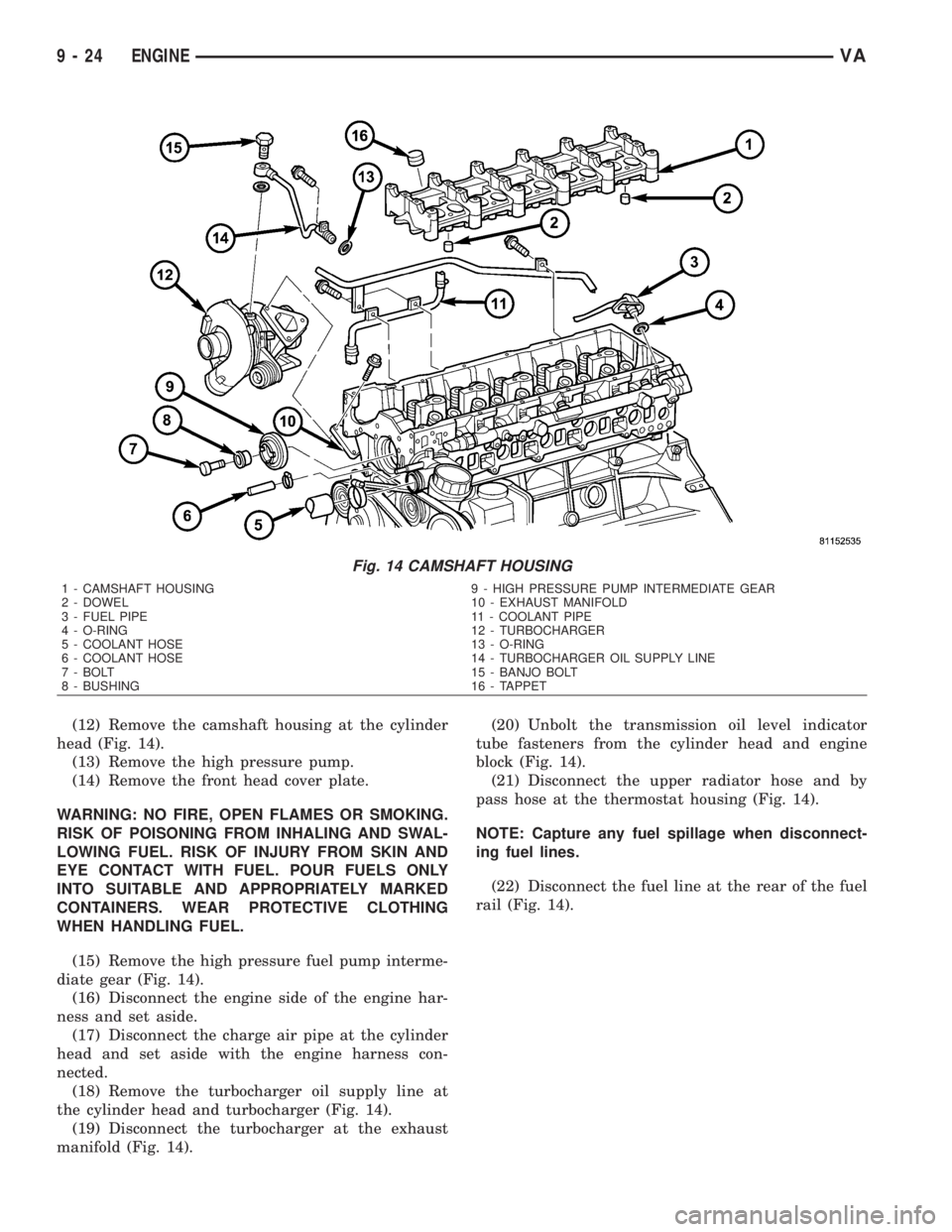
(12) Remove the camshaft housing at the cylinder
head (Fig. 14).
(13) Remove the high pressure pump.
(14) Remove the front head cover plate.
WARNING: NO FIRE, OPEN FLAMES OR SMOKING.
RISK OF POISONING FROM INHALING AND SWAL-
LOWING FUEL. RISK OF INJURY FROM SKIN AND
EYE CONTACT WITH FUEL. POUR FUELS ONLY
INTO SUITABLE AND APPROPRIATELY MARKED
CONTAINERS. WEAR PROTECTIVE CLOTHING
WHEN HANDLING FUEL.
(15) Remove the high pressure fuel pump interme-
diate gear (Fig. 14).
(16) Disconnect the engine side of the engine har-
ness and set aside.
(17) Disconnect the charge air pipe at the cylinder
head and set aside with the engine harness con-
nected.
(18) Remove the turbocharger oil supply line at
the cylinder head and turbocharger (Fig. 14).
(19) Disconnect the turbocharger at the exhaust
manifold (Fig. 14).(20) Unbolt the transmission oil level indicator
tube fasteners from the cylinder head and engine
block (Fig. 14).
(21) Disconnect the upper radiator hose and by
pass hose at the thermostat housing (Fig. 14).
NOTE: Capture any fuel spillage when disconnect-
ing fuel lines.
(22) Disconnect the fuel line at the rear of the fuel
rail (Fig. 14).
Fig. 14 CAMSHAFT HOUSING
1 - CAMSHAFT HOUSING 9 - HIGH PRESSURE PUMP INTERMEDIATE GEAR
2 - DOWEL 10 - EXHAUST MANIFOLD
3 - FUEL PIPE 11 - COOLANT PIPE
4 - O-RING 12 - TURBOCHARGER
5 - COOLANT HOSE 13 - O-RING
6 - COOLANT HOSE 14 - TURBOCHARGER OIL SUPPLY LINE
7 - BOLT 15 - BANJO BOLT
8 - BUSHING 16 - TAPPET
9 - 24 ENGINEVA
Page 1602 of 2305
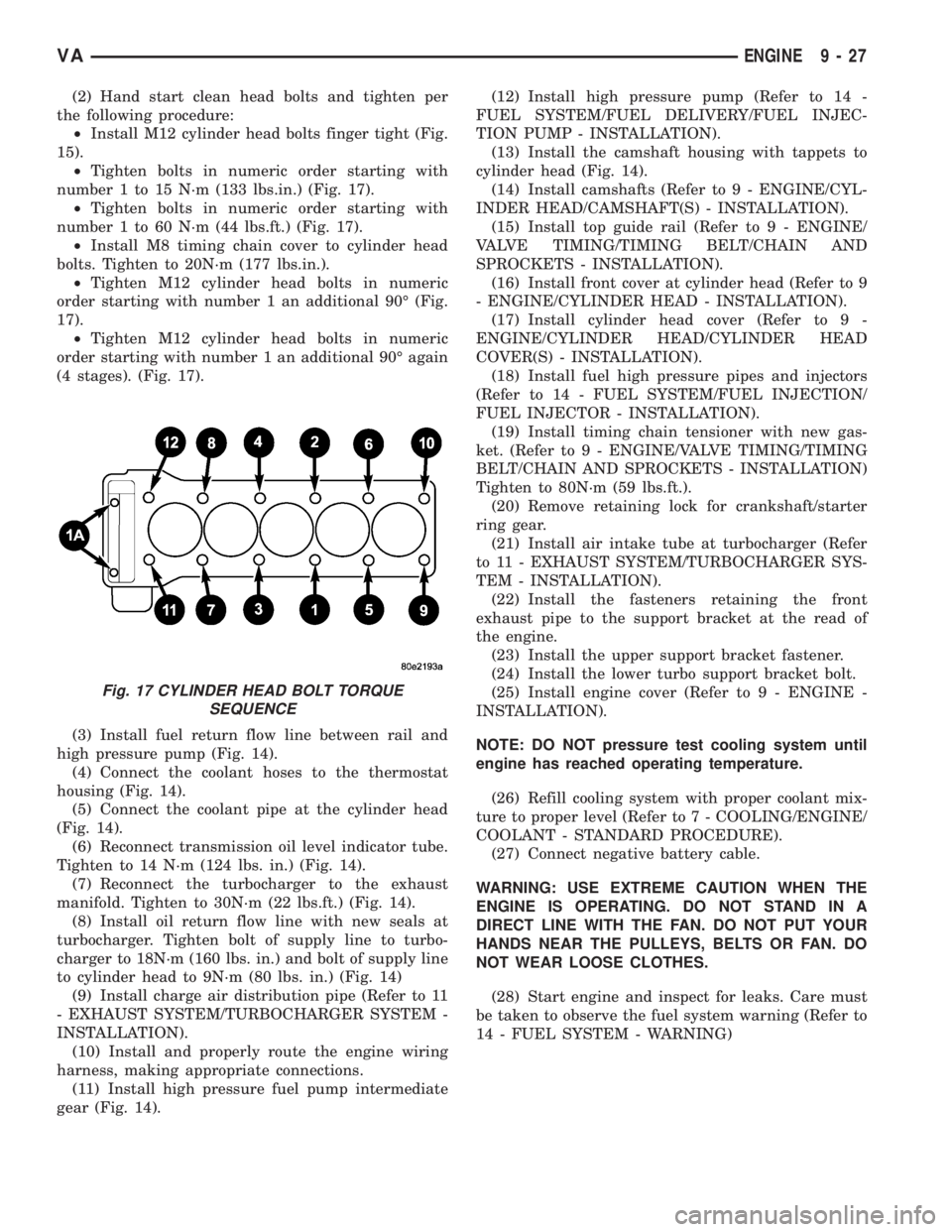
(2) Hand start clean head bolts and tighten per
the following procedure:
²Install M12 cylinder head bolts finger tight (Fig.
15).
²Tighten bolts in numeric order starting with
number 1 to 15 N´m (133 lbs.in.) (Fig. 17).
²Tighten bolts in numeric order starting with
number 1 to 60 N´m (44 lbs.ft.) (Fig. 17).
²Install M8 timing chain cover to cylinder head
bolts. Tighten to 20N´m (177 lbs.in.).
²Tighten M12 cylinder head bolts in numeric
order starting with number 1 an additional 90É (Fig.
17).
²Tighten M12 cylinder head bolts in numeric
order starting with number 1 an additional 90É again
(4 stages). (Fig. 17).
(3) Install fuel return flow line between rail and
high pressure pump (Fig. 14).
(4) Connect the coolant hoses to the thermostat
housing (Fig. 14).
(5) Connect the coolant pipe at the cylinder head
(Fig. 14).
(6) Reconnect transmission oil level indicator tube.
Tighten to 14 N´m (124 lbs. in.) (Fig. 14).
(7) Reconnect the turbocharger to the exhaust
manifold. Tighten to 30N´m (22 lbs.ft.) (Fig. 14).
(8) Install oil return flow line with new seals at
turbocharger. Tighten bolt of supply line to turbo-
charger to 18N´m (160 lbs. in.) and bolt of supply line
to cylinder head to 9N´m (80 lbs. in.) (Fig. 14)
(9) Install charge air distribution pipe (Refer to 11
- EXHAUST SYSTEM/TURBOCHARGER SYSTEM -
INSTALLATION).
(10) Install and properly route the engine wiring
harness, making appropriate connections.
(11) Install high pressure fuel pump intermediate
gear (Fig. 14).(12) Install high pressure pump (Refer to 14 -
FUEL SYSTEM/FUEL DELIVERY/FUEL INJEC-
TION PUMP - INSTALLATION).
(13) Install the camshaft housing with tappets to
cylinder head (Fig. 14).
(14) Install camshafts (Refer to 9 - ENGINE/CYL-
INDER HEAD/CAMSHAFT(S) - INSTALLATION).
(15) Install top guide rail (Refer to 9 - ENGINE/
VALVE TIMING/TIMING BELT/CHAIN AND
SPROCKETS - INSTALLATION).
(16) Install front cover at cylinder head (Refer to 9
- ENGINE/CYLINDER HEAD - INSTALLATION).
(17) Install cylinder head cover (Refer to 9 -
ENGINE/CYLINDER HEAD/CYLINDER HEAD
COVER(S) - INSTALLATION).
(18) Install fuel high pressure pipes and injectors
(Refer to 14 - FUEL SYSTEM/FUEL INJECTION/
FUEL INJECTOR - INSTALLATION).
(19) Install timing chain tensioner with new gas-
ket. (Refer to 9 - ENGINE/VALVE TIMING/TIMING
BELT/CHAIN AND SPROCKETS - INSTALLATION)
Tighten to 80N´m (59 lbs.ft.).
(20) Remove retaining lock for crankshaft/starter
ring gear.
(21) Install air intake tube at turbocharger (Refer
to 11 - EXHAUST SYSTEM/TURBOCHARGER SYS-
TEM - INSTALLATION).
(22) Install the fasteners retaining the front
exhaust pipe to the support bracket at the read of
the engine.
(23) Install the upper support bracket fastener.
(24) Install the lower turbo support bracket bolt.
(25) Install engine cover (Refer to 9 - ENGINE -
INSTALLATION).
NOTE: DO NOT pressure test cooling system until
engine has reached operating temperature.
(26) Refill cooling system with proper coolant mix-
ture to proper level (Refer to 7 - COOLING/ENGINE/
COOLANT - STANDARD PROCEDURE).
(27) Connect negative battery cable.
WARNING: USE EXTREME CAUTION WHEN THE
ENGINE IS OPERATING. DO NOT STAND IN A
DIRECT LINE WITH THE FAN. DO NOT PUT YOUR
HANDS NEAR THE PULLEYS, BELTS OR FAN. DO
NOT WEAR LOOSE CLOTHES.
(28) Start engine and inspect for leaks. Care must
be taken to observe the fuel system warning (Refer to
14 - FUEL SYSTEM - WARNING)
Fig. 17 CYLINDER HEAD BOLT TORQUE
SEQUENCE
VAENGINE 9 - 27
Page 1616 of 2305
CAUTION: Oil thread and head contact surfaces of
bolts that retain the crankshaft bearing caps;
tighten bolts from inside to outside, beginning at
the fit bearing. Rotate crankshaft to check clear-
ance.
(1) Install crankshaft.
CAUTION: The crankshaft bearing caps are num-
bered consecutively, beginning with the first crank-
shaft bearing cap at the front of the engine.
Attention must be paid to the way the crankshaft
bearing caps fit. If correctly installed, the lug, or
raised boss, on the crankshaft bearing cap is point-
ing to the left when viewed in the direction of travel
(intake side).
(2) Install the crankshaft bearing caps. Tighten
bolts in two stages. 55N´m (40.5 lbs. ft.), then 90É.
(3) Install the pistons (Refer to 9 - ENGINE/EN-
GINE BLOCK/PISTON & CONNECTING ROD -
INSTALLATION).
(4) Install the end cover (Refer to 9 - ENGINE/EN-
GINE BLOCK/CRANKSHAFT OIL SEAL - REAR -
INSTALLATION).
(5) Install the timing case cover (Refer to 9 -
ENGINE/VALVE TIMING/TIMING BELT / CHAIN
COVER(S) - INSTALLATION).
(6) Install the engine (Refer to 9 - ENGINE -
INSTALLATION).
(7) Fill the crankcase with the correct engine oil,
to the proper level. Refer to the owners manual for
specifications.
(8) Fill the cooling system with the proper coolant,
to the proper level (Refer to 7 - COOLING/ENGINE/
COOLANT - STANDARD PROCEDURE).
(9) Connect the negative battery cable.
WARNING: USE EXTREME CAUTION WHEN THE
ENGINE IS OPERATING. DO NOT STAND IN A
DIRECT LINE WITH THE FAN. DO NOT PUT YOUR
HANDS NEAR THE PULLEYS, BELTS, OR FAN. DO
NOT WEAR LOOSE CLOTHES.
(10) Start engine and inspect for leaks. Care must
be taken to observe the fuel system warning (Refer to
14 - FUEL SYSTEM - WARNING).
CRANKSHAFT OIL SEAL -
REAR
REMOVAL
This must be done with the transmission removed
from the vehicle.
(1) Disconnect the negative battery cable.
(2) Raise and support the vehicle.
(3) Drain the engine oil.NOTE: Loosen all of the oil pan bolts to assure that
the oil pan gasket is not damaged when removing
the rear main oil seal and end cover assembly.
NOTE: Inspect the oil pan gasket for damage. If the
oil pan gasket is damaged, remove the oil pan and
replace the oil pan gasket.
(4) Loosen the oil pan bolts.
(5) Remove the flywheel.
CAUTION: Care must be taken when removing the
rear main seal and adaptor assembly. Failure to do
so will result in damage to the oil pan gasket.
(6) Remove the rear main seal/adaptor retaining
bolts and carefully pry the adaptor from the crank-
case at the adaptor shoulders (Fig. 33).
VAENGINE 9 - 41
Page 1627 of 2305
(19) Fill the cooing system with proper coolant, to
the proper level (Refer to 7 - COOLING/ENGINE/
COOLANT - STANDARD PROCEDURE).
(20) Connect negative battery cable.
WARNING: USE EXTREME CAUTION WHEN THE
ENGINE IS OPERATING. DO NOT STAND IN A
DIRECT LINE WITH THE FAN. DO NOT PUT YOUR
HANDS NEAR THE PULLEYS, BELTS, OR FAN. DO
NOT WEAR LOOSE CLOTHES.
WARNING: (Refer to 14 - FUEL SYSTEM - WARN-
ING).
(21) Start the engine and inspect for leaks.
PISTON RINGS
STANDARD PROCEDURE - PISTON RING FIT-
TING
(1) Carefully clean the carbon from all ring
grooves. Oil drain openings in the oil ring groove and
pin boss must be clear. DO NOT remove metal from
the grooves or lands. This will change ring-to-groove
clearances and will damage the ring-to-land seating.
(2) Be sure the piston ring grooves are free of
nicks and burrs.
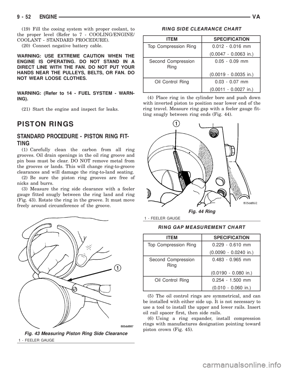
(3) Measure the ring side clearance with a feeler
gauge fitted snugly between the ring land and ring
(Fig. 43). Rotate the ring in the groove. It must move
freely around circumference of the groove.
RING SIDE CLEARANCE CHART
ITEM SPECIFICATION
Top Compression Ring 0.012 - 0.016 mm
(0.0047 - 0.0063 in.)
Second Compression
Ring0.05 - 0.09 mm
(0.0019 - 0.0035 in.)
Oil Control Ring 0.03 - 0.07 mm
(0.0011 - 0.0027 in.)
(4) Place ring in the cylinder bore and push down
with inverted piston to position near lower end of the
ring travel. Measure ring gap with a feeler gauge fit-
ting snugly between ring ends (Fig. 44).
RING GAP MEASUREMENT CHART
ITEM SPECIFICATION
Top Compression Ring 0.229 - 0.610 mm
(0.0090 - 0.0240 in.)
Second Compression
Ring0.483 - 0.965 mm
(0.0190 - 0.080 in.)
Oil Control Ring 0.254 - 1.500 mm
(0.010 - 0.060 in.)
(5) The oil control rings are symmetrical, and can
be installed with either side up. It is not necessary to
use a tool to install the upper and lower rails. Insert
oil rail spacer first, then side rails.
(6) Using a ring expander, install compression
rings with manufactures designation pointing toward
piston crown (Fig. 45).
Fig. 43 Measuring Piston Ring Side Clearance
1 - FEELER GAUGE
Fig. 44 Ring
1 - FEELER GAUGE
9 - 52 ENGINEVA
Page 1628 of 2305
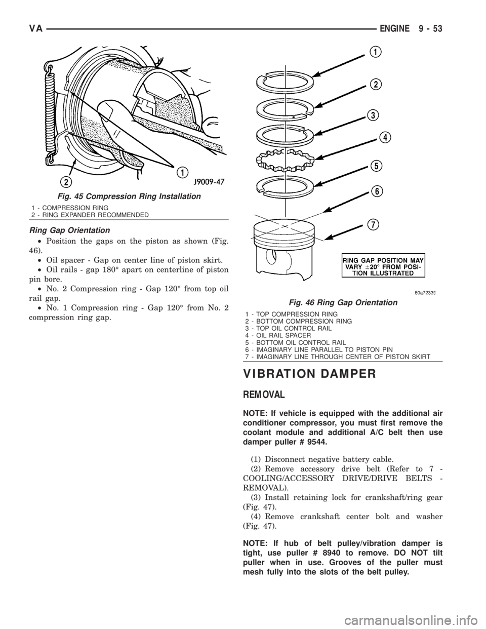
Ring Gap Orientation
²Position the gaps on the piston as shown (Fig.
46).
²Oil spacer - Gap on center line of piston skirt.
²Oil rails - gap 180É apart on centerline of piston
pin bore.
²No. 2 Compression ring - Gap 120É from top oil
rail gap.
²No. 1 Compression ring - Gap 120É from No. 2
compression ring gap.
VIBRATION DAMPER
REMOVAL
NOTE: If vehicle is equipped with the additional air
conditioner compressor, you must first remove the
coolant module and additional A/C belt then use
damper puller # 9544.
(1) Disconnect negative battery cable.
(2) Remove accessory drive belt (Refer to 7 -
COOLING/ACCESSORY DRIVE/DRIVE BELTS -
REMOVAL).
(3) Install retaining lock for crankshaft/ring gear
(Fig. 47).
(4) Remove crankshaft center bolt and washer
(Fig. 47).
NOTE: If hub of belt pulley/vibration damper is
tight, use puller # 8940 to remove. DO NOT tilt
puller when in use. Grooves of the puller must
mesh fully into the slots of the belt pulley.
Fig. 45 Compression Ring Installation
1 - COMPRESSION RING
2 - RING EXPANDER RECOMMENDED
Fig. 46 Ring Gap Orientation
1 - TOP COMPRESSION RING
2 - BOTTOM COMPRESSION RING
3 - TOP OIL CONTROL RAIL
4 - OIL RAIL SPACER
5 - BOTTOM OIL CONTROL RAIL
6 - IMAGINARY LINE PARALLEL TO PISTON PIN
7 - IMAGINARY LINE THROUGH CENTER OF PISTON SKIRT
VAENGINE 9 - 53