2006 MERCEDES-BENZ SPRINTER engine coolant
[x] Cancel search: engine coolantPage 1688 of 2305
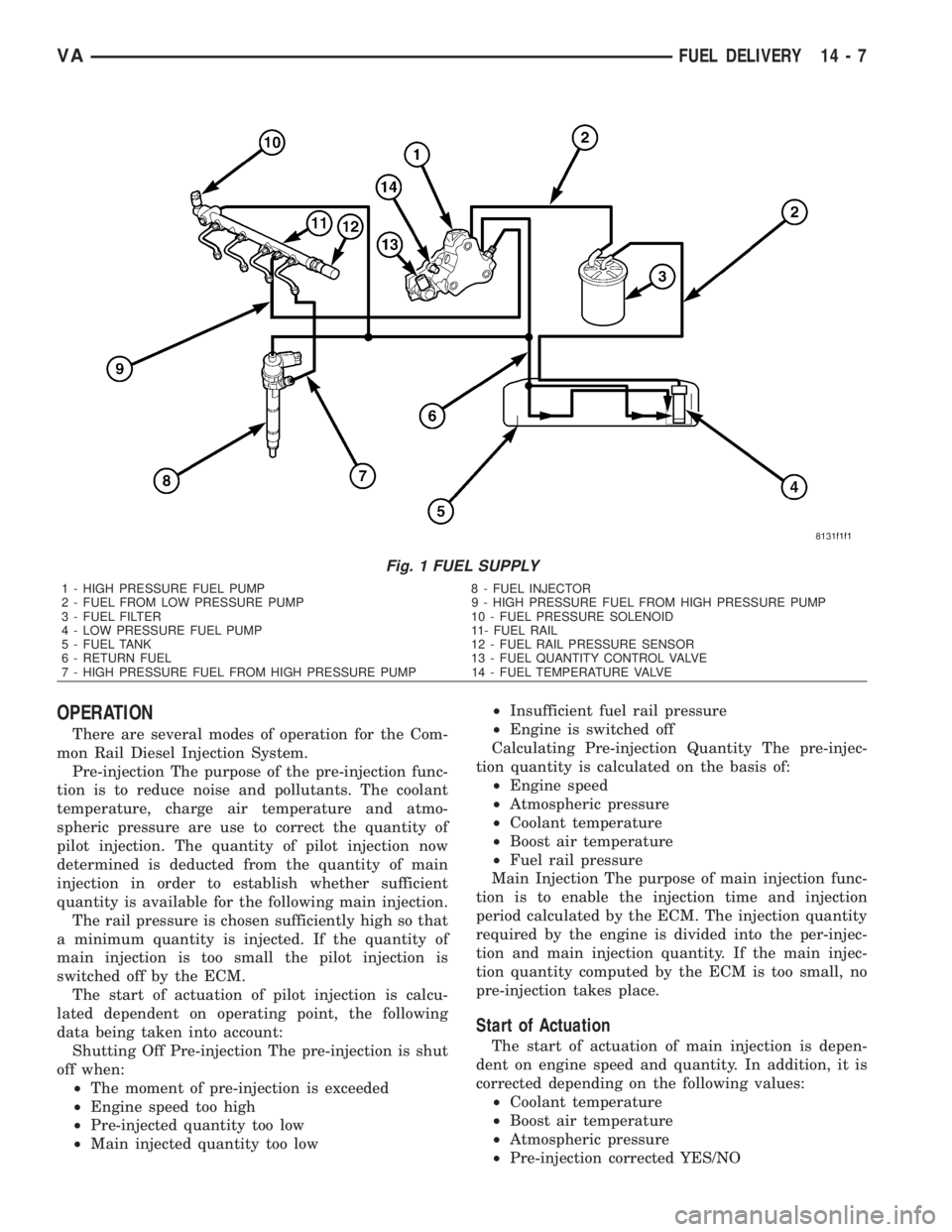
OPERATION
There are several modes of operation for the Com-
mon Rail Diesel Injection System.
Pre-injection The purpose of the pre-injection func-
tion is to reduce noise and pollutants. The coolant
temperature, charge air temperature and atmo-
spheric pressure are use to correct the quantity of
pilot injection. The quantity of pilot injection now
determined is deducted from the quantity of main
injection in order to establish whether sufficient
quantity is available for the following main injection.
The rail pressure is chosen sufficiently high so that
a minimum quantity is injected. If the quantity of
main injection is too small the pilot injection is
switched off by the ECM.
The start of actuation of pilot injection is calcu-
lated dependent on operating point, the following
data being taken into account:
Shutting Off Pre-injection The pre-injection is shut
off when:
²The moment of pre-injection is exceeded
²Engine speed too high
²Pre-injected quantity too low
²Main injected quantity too low²Insufficient fuel rail pressure
²Engine is switched off
Calculating Pre-injection Quantity The pre-injec-
tion quantity is calculated on the basis of:
²Engine speed
²Atmospheric pressure
²Coolant temperature
²Boost air temperature
²Fuel rail pressure
Main Injection The purpose of main injection func-
tion is to enable the injection time and injection
period calculated by the ECM. The injection quantity
required by the engine is divided into the per-injec-
tion and main injection quantity. If the main injec-
tion quantity computed by the ECM is too small, no
pre-injection takes place.
Start of Actuation
The start of actuation of main injection is depen-
dent on engine speed and quantity. In addition, it is
corrected depending on the following values:
²Coolant temperature
²Boost air temperature
²Atmospheric pressure
²Pre-injection corrected YES/NO
Fig. 1 FUEL SUPPLY
1 - HIGH PRESSURE FUEL PUMP 8 - FUEL INJECTOR
2 - FUEL FROM LOW PRESSURE PUMP 9 - HIGH PRESSURE FUEL FROM HIGH PRESSURE PUMP
3 - FUEL FILTER 10 - FUEL PRESSURE SOLENOID
4 - LOW PRESSURE FUEL PUMP 11- FUEL RAIL
5 - FUEL TANK 12 - FUEL RAIL PRESSURE SENSOR
6 - RETURN FUEL 13 - FUEL QUANTITY CONTROL VALVE
7 - HIGH PRESSURE FUEL FROM HIGH PRESSURE PUMP 14 - FUEL TEMPERATURE VALVE
VAFUEL DELIVERY 14 - 7
Page 1689 of 2305
Switching Off Main Injection
Main injection is switched off when:
²Engine speed is too high >4700 - 4800 rpm
²Main injection quantity too low
²Low fuel pressure in fuel rail
²Engine off
²External quantity control
²Deceleration mode
Calculating Main Injection
The quantity of main injection is calculated by:
²Engine speed
²Atmospheric pressure
²Coolant temperature
²Boost air temperature
²Fuel rail pressure
²Boost pressure
Period of Actuation
For calculating the period of actuation of the main
injection it is necessary to know whether a pre-injec-
tion has occurred or not.
The coolant temperature, charge air temperature
and the atmospheric pressure are used for correcting
the main injection quantity. If main injection quan-
tity is less than a minimum quantity which is depen-
dent on fuel rail pressure, no preinjection takes
place. In this case, only main injection is performed.
If the quantity is then still below the minimum
quantity, neither main injection or pre-injection takes
place (deceleration mode).
Deceleration Mode
The purpose of the deceleration mode is to inter-
rupt the operation of the injectors. The ECM deter-
mines the accelerator pedal position from a supplied
signal and it determines the engine speed by the
crank sensor. In the overrun and with the engine
speed above 1600, with the accelerator pedal no
pressed, the injectors are no longer actuated and the
fuel rail pressure is lowered by the pressure regula-
tor valve.
Full Load Injected Quantity
The purpose of the full load injected quantity is to
minimize the formation of smoke. The ECM limits
the fuel rail pressure when the engine is operating at
full load by way of the quantity control valve, and
quantity of fuel injected by the injectors. this mini-
mizes the formation of smoke when accelerating and
driving at constant speeds. If a fault occurs at the
boost pressure control, full load injected quantity is
reduced.
Limiting Maximum Engine Speed
The ECM determines the engine speed based on
the signal supplied by the crankshaft sensor and lim-its this by interrupting the operation of the fuel
injectors.
Fuel Quantity Control
The fuel quantity is controlled separately for each
cylinder by the ECM inline with the firing order.The
ECM detects the operating state which exists at the
engine by means of the sensors. In order adapt the
quantity injected, either the fuel rail pressure can be
adjusted by the fuel solenoid and quantity control
valve or the actuation time of the solenoid valves in
the injectors
Boiling Protection
In order to protect against thermal overload and
along with criteria programmed in the ECM, the
injection quantity is reduced as a function of the cool-
ant temperature and vehicle speed. If the coolant
temperature sensor fails the oil temperature signal
from the oil sensor is used as a suitable value.
Fuel Tank Protection
The fuel rail pressure is lowered in order to protect
the fuel tank from overheating. The fuel temperature
sensor measures the temperature of the fuel being
supplied from the tank, in the high pressure flange.
If the fuel is too warm the fuel rail pressure is fur-
ther reduced by the quantity control valve.
STANDARD PROCEDURE
STANDARD PROCEDURE - DRAINING FUEL
TANK - DIESEL
(1) Position a drain hose into the fuel fill opening.
(2) Drain fuel tank using an approved diesel fuel
draining station.
FUEL CONTAMINATION
If a diesel engine's fuel supply has been contami-
nated with gasoline, the following procedure must be
followed:
(1) Remove all fuel from the fuel tank. (Refer to 14
- FUEL SYSTEM/FUEL DELIVERY - STANDARD
PROCEDURE-DRAINING FUEL TANK) Use an
appropriate fuel container. Dispose of the contami-
nated fuel using the proper procedures.
CAUTION: Dispose of petroleum based products in
a manner consistent with all applicable Local, State,
Federal, and Provincial regulations.
(2) Remove and clean fuel tank. (Refer to 14 -
FUEL SYSTEM/FUEL DELIVERY/FUEL TANK -
REMOVAL)
(3) Install the fuel tank. (Refer to 14 - FUEL SYS-
TEM/FUEL DELIVERY/FUEL TANK - INSTALLA-
TION)
14 - 8 FUEL DELIVERYVA
Page 1693 of 2305
INSTALLATION - HIGH PRESSURE LINES
WARNING: NO SPARKS, OPEN FLAMES OR SMOK-
ING. RISK OF POISONING FROM INHALING AND
SWALLOWING FUEL. RISK OF INJURY TO EYES
AND SKIN FROM CONTACT WITH FUEL. POUR
FUELS ONLY INTO SUITABLE AND APPROPRI-
ATELY MARKED CONTAINERS. WEAR PROTECTIVE
CLOTHING.
(1) Loosen the fuel rail mounting bolts to install
lines free of stress.
CAUTION: Inspect sealing cone at lines. Replace if
compression points exist. Ensure lines are exactly
located.
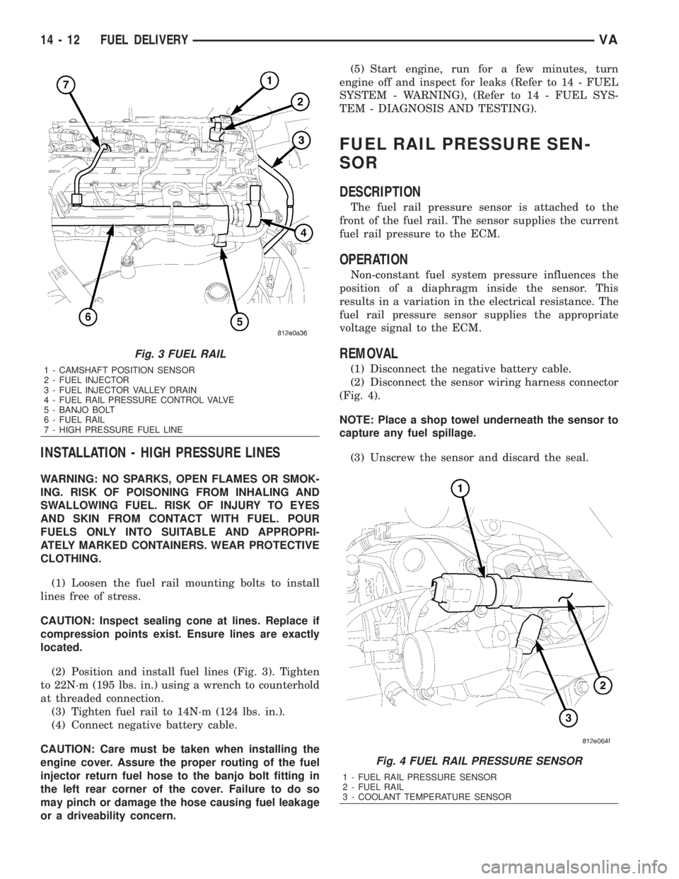
(2) Position and install fuel lines (Fig. 3). Tighten
to 22N´m (195 lbs. in.) using a wrench to counterhold
at threaded connection.
(3) Tighten fuel rail to 14N´m (124 lbs. in.).
(4) Connect negative battery cable.
CAUTION: Care must be taken when installing the
engine cover. Assure the proper routing of the fuel
injector return fuel hose to the banjo bolt fitting in
the left rear corner of the cover. Failure to do so
may pinch or damage the hose causing fuel leakage
or a driveability concern.(5) Start engine, run for a few minutes, turn
engine off and inspect for leaks (Refer to 14 - FUEL
SYSTEM - WARNING), (Refer to 14 - FUEL SYS-
TEM - DIAGNOSIS AND TESTING).
FUEL RAIL PRESSURE SEN-
SOR
DESCRIPTION
The fuel rail pressure sensor is attached to the
front of the fuel rail. The sensor supplies the current
fuel rail pressure to the ECM.
OPERATION
Non-constant fuel system pressure influences the
position of a diaphragm inside the sensor. This
results in a variation in the electrical resistance. The
fuel rail pressure sensor supplies the appropriate
voltage signal to the ECM.
REMOVAL
(1) Disconnect the negative battery cable.
(2) Disconnect the sensor wiring harness connector
(Fig. 4).
NOTE: Place a shop towel underneath the sensor to
capture any fuel spillage.
(3) Unscrew the sensor and discard the seal.
Fig. 3 FUEL RAIL
1 - CAMSHAFT POSITION SENSOR
2 - FUEL INJECTOR
3 - FUEL INJECTOR VALLEY DRAIN
4 - FUEL RAIL PRESSURE CONTROL VALVE
5 - BANJO BOLT
6 - FUEL RAIL
7 - HIGH PRESSURE FUEL LINE
Fig. 4 FUEL RAIL PRESSURE SENSOR
1 - FUEL RAIL PRESSURE SENSOR
2 - FUEL RAIL
3 - COOLANT TEMPERATURE SENSOR
14 - 12 FUEL DELIVERYVA
Page 1875 of 2305
CAUSES OF BURNT FLUID
Burnt, discolored fluid is a result of overheating
which has three primary causes.
1. Internal clutch slippage, usually caused by low
line pressure, inadequate clutch apply pressure, or
clutch seal failure.
2. A result of restricted fluid flow through the
main and/or auxiliary cooler. This condition is usu-
ally the result of a faulty or improperly installed
drainback valve, a damaged oil cooler, or severe
restrictions in the coolers and lines caused by debris
or kinked lines.
3. Heavy duty operation with a vehicle not prop-
erly equipped for this type of operation. Trailer tow-
ing or similar high load operation will overheat the
transmission fluid if the vehicle is improperly
equipped. Such vehicles should have an auxiliary
transmission fluid cooler, a heavy duty cooling sys-
tem, and the engine/axle ratio combination needed to
handle heavy loads.
FLUID CONTAMINATION
Transmission fluid contamination is generally a
result of:
²adding incorrect fluid
²failure to clean dipstick and fill tube when
checking level
²engine coolant entering the fluid
²internal failure that generates debris
²overheat that generates sludge (fluid break-
down)
²failure to replace contaminated converter after
repair
The use of non-recommended fluids can result in
transmission failure. The usual results are erratic
shifts, slippage, abnormal wear and eventual failure
due to fluid breakdown and sludge formation. Avoid
this condition by using recommended fluids only.
The dipstick cap and fill tube should be wiped
clean before checking fluid level. Dirt, grease and
other foreign material on the cap and tube could fall
into the tube if not removed beforehand. Take the
time to wipe the cap and tube clean before withdraw-
ing the dipstick.
Engine coolant in the transmission fluid is gener-
ally caused by a cooler malfunction. The only remedy
is to replace the radiator as the cooler in the radiator
is not a serviceable part. If coolant has circulated
through the transmission, an overhaul is necessary.
The torque converter should be replaced whenever
a failure generates sludge and debris. This is neces-
sary because normal converter flushing procedures
will not remove all contaminants.
STANDARD PROCEDURE
CHECK OIL LEVEL
(1) Verify that the vehicle is parked on a level sur-
face.
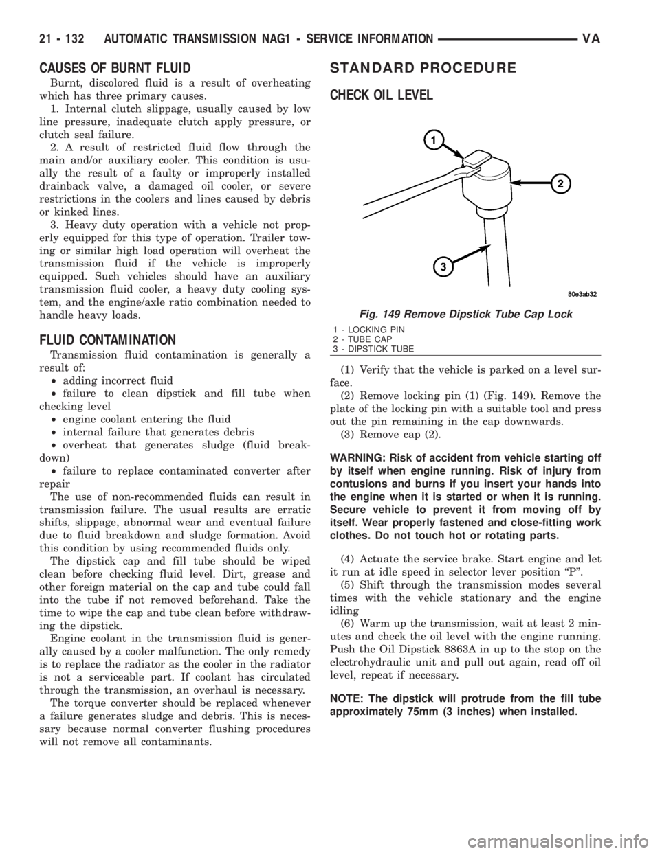
(2) Remove locking pin (1) (Fig. 149). Remove the
plate of the locking pin with a suitable tool and press
out the pin remaining in the cap downwards.
(3) Remove cap (2).
WARNING: Risk of accident from vehicle starting off
by itself when engine running. Risk of injury from
contusions and burns if you insert your hands into
the engine when it is started or when it is running.
Secure vehicle to prevent it from moving off by
itself. Wear properly fastened and close-fitting work
clothes. Do not touch hot or rotating parts.
(4) Actuate the service brake. Start engine and let
it run at idle speed in selector lever position ªPº.
(5) Shift through the transmission modes several
times with the vehicle stationary and the engine
idling
(6) Warm up the transmission, wait at least 2 min-
utes and check the oil level with the engine running.
Push the Oil Dipstick 8863A in up to the stop on the
electrohydraulic unit and pull out again, read off oil
level, repeat if necessary.
NOTE: The dipstick will protrude from the fill tube
approximately 75mm (3 inches) when installed.
Fig. 149 Remove Dipstick Tube Cap Lock
1 - LOCKING PIN
2 - TUBE CAP
3 - DIPSTICK TUBE
21 - 132 AUTOMATIC TRANSMISSION NAG1 - SERVICE INFORMATIONVA
Page 1925 of 2305
²Transmission fluid temperature
²Engine coolant temperature
²Input speed
²Throttle angle
²Engine speed
OPERATION
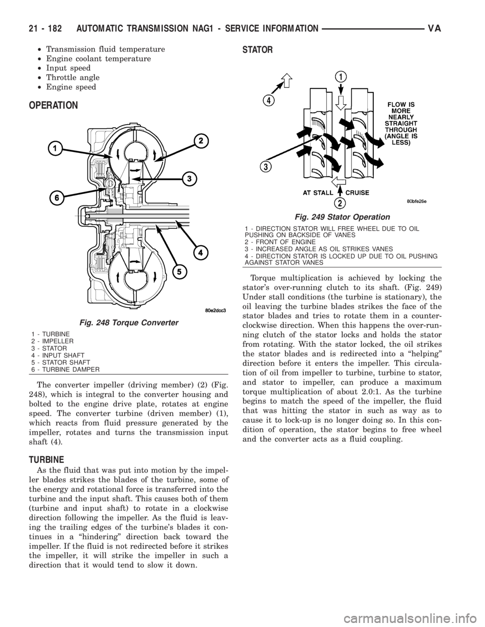
The converter impeller (driving member) (2) (Fig.
248), which is integral to the converter housing and
bolted to the engine drive plate, rotates at engine
speed. The converter turbine (driven member) (1),
which reacts from fluid pressure generated by the
impeller, rotates and turns the transmission input
shaft (4).
TURBINE
As the fluid that was put into motion by the impel-
ler blades strikes the blades of the turbine, some of
the energy and rotational force is transferred into the
turbine and the input shaft. This causes both of them
(turbine and input shaft) to rotate in a clockwise
direction following the impeller. As the fluid is leav-
ing the trailing edges of the turbine's blades it con-
tinues in a ªhinderingº direction back toward the
impeller. If the fluid is not redirected before it strikes
the impeller, it will strike the impeller in such a
direction that it would tend to slow it down.
STATOR
Torque multiplication is achieved by locking the
stator's over-running clutch to its shaft. (Fig. 249)
Under stall conditions (the turbine is stationary), the
oil leaving the turbine blades strikes the face of the
stator blades and tries to rotate them in a counter-
clockwise direction. When this happens the over-run-
ning clutch of the stator locks and holds the stator
from rotating. With the stator locked, the oil strikes
the stator blades and is redirected into a ªhelpingº
direction before it enters the impeller. This circula-
tion of oil from impeller to turbine, turbine to stator,
and stator to impeller, can produce a maximum
torque multiplication of about 2.0:1. As the turbine
begins to match the speed of the impeller, the fluid
that was hitting the stator in such as way as to
cause it to lock-up is no longer doing so. In this con-
dition of operation, the stator begins to free wheel
and the converter acts as a fluid coupling.
Fig. 248 Torque Converter
1 - TURBINE
2 - IMPELLER
3-STATOR
4 - INPUT SHAFT
5 - STATOR SHAFT
6 - TURBINE DAMPER
Fig. 249 Stator Operation
1 - DIRECTION STATOR WILL FREE WHEEL DUE TO OIL
PUSHING ON BACKSIDE OF VANES
2 - FRONT OF ENGINE
3 - INCREASED ANGLE AS OIL STRIKES VANES
4 - DIRECTION STATOR IS LOCKED UP DUE TO OIL PUSHING
AGAINST STATOR VANES
21 - 182 AUTOMATIC TRANSMISSION NAG1 - SERVICE INFORMATIONVA
Page 2038 of 2305
HEATING & AIR CONDITIONING
TABLE OF CONTENTS
page page
HEATING & AIR CONDITIONING
DESCRIPTION..........................1
OPERATION............................2
DIAGNOSIS AND TESTING
A/C PERFORMANCE....................3
HEATER PERFORMANCE TEST...........5
ATC FUNCTION TEST...................6
SPECIFICATIONS
HEATING-A/C SYSTEM..................6CONTROLS-FRONT........................8
CONTROLS - REAR......................24
DISTRIBUTION - FRONT...................45
DISTRIBUTION - REAR....................52
PLUMBING.............................60
CABIN HEATER.........................104
HEATING & AIR CONDITION-
ING
DESCRIPTION
An automatic temperature control (ATC) single
zone type heating-A/C system is standard equipment
on this model.
To maintain the performance level of the heating,
ventilation and air conditioning (HVAC) system, the
engine cooling system must be properly maintained.
The use of a bug screen is not recommended. Any
obstructions in front of the radiator or A/C condenser
will reduce the performance of the A/C and engine
cooling systems.
The engine cooling system includes the radiator,
thermostat, radiator hoses and the engine coolant
pump. Refer to 7 - Cooling for more information
before opening or attempting any service to the
engine cooling system.
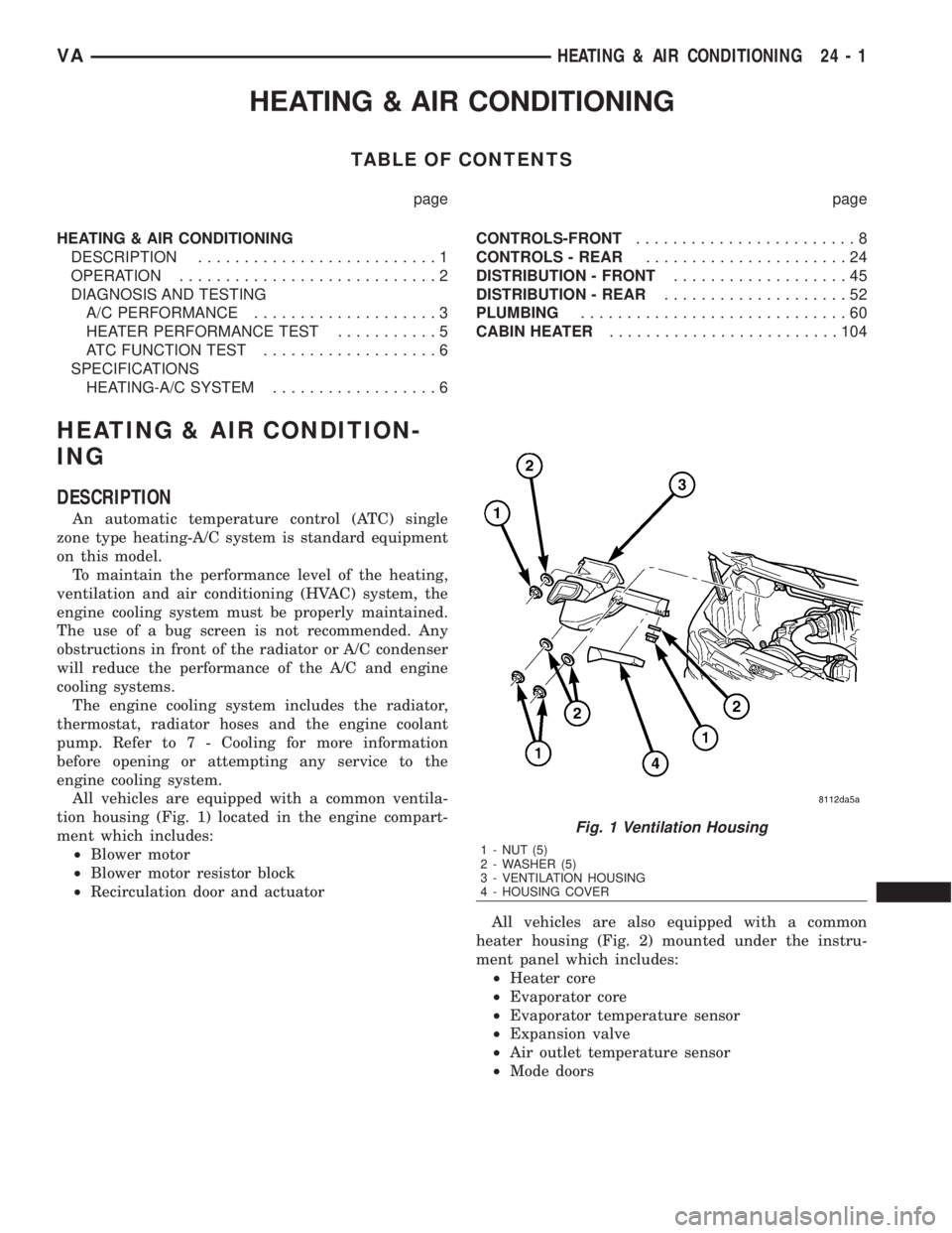
All vehicles are equipped with a common ventila-
tion housing (Fig. 1) located in the engine compart-
ment which includes:
²Blower motor
²Blower motor resistor block
²Recirculation door and actuator
All vehicles are also equipped with a common
heater housing (Fig. 2) mounted under the instru-
ment panel which includes:
²Heater core
²Evaporator core
²Evaporator temperature sensor
²Expansion valve
²Air outlet temperature sensor
²Mode doors
Fig. 1 Ventilation Housing
1 - NUT (5)
2 - WASHER (5)
3 - VENTILATION HOUSING
4 - HOUSING COVER
VAHEATING & AIR CONDITIONING 24 - 1
Page 2039 of 2305
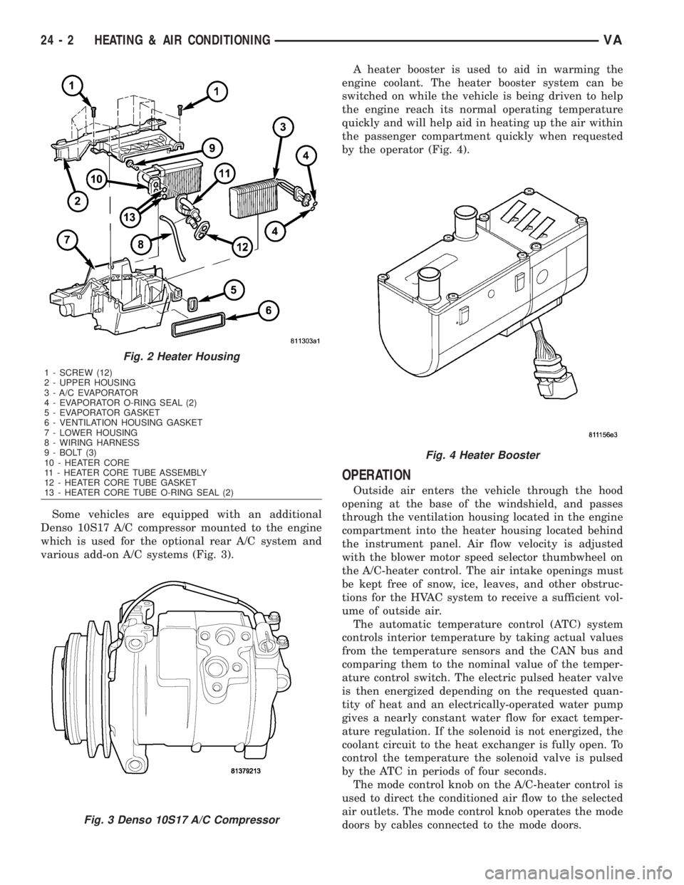
Some vehicles are equipped with an additional
Denso 10S17 A/C compressor mounted to the engine
which is used for the optional rear A/C system and
various add-on A/C systems (Fig. 3).A heater booster is used to aid in warming the
engine coolant. The heater booster system can be
switched on while the vehicle is being driven to help
the engine reach its normal operating temperature
quickly and will help aid in heating up the air within
the passenger compartment quickly when requested
by the operator (Fig. 4).
OPERATION
Outside air enters the vehicle through the hood
opening at the base of the windshield, and passes
through the ventilation housing located in the engine
compartment into the heater housing located behind
the instrument panel. Air flow velocity is adjusted
with the blower motor speed selector thumbwheel on
the A/C-heater control. The air intake openings must
be kept free of snow, ice, leaves, and other obstruc-
tions for the HVAC system to receive a sufficient vol-
ume of outside air.
The automatic temperature control (ATC) system
controls interior temperature by taking actual values
from the temperature sensors and the CAN bus and
comparing them to the nominal value of the temper-
ature control switch. The electric pulsed heater valve
is then energized depending on the requested quan-
tity of heat and an electrically-operated water pump
gives a nearly constant water flow for exact temper-
ature regulation. If the solenoid is not energized, the
coolant circuit to the heat exchanger is fully open. To
control the temperature the solenoid valve is pulsed
by the ATC in periods of four seconds.
The mode control knob on the A/C-heater control is
used to direct the conditioned air flow to the selected
air outlets. The mode control knob operates the mode
doors by cables connected to the mode doors.
Fig. 2 Heater Housing
1 - SCREW (12)
2 - UPPER HOUSING
3 - A/C EVAPORATOR
4 - EVAPORATOR O-RING SEAL (2)
5 - EVAPORATOR GASKET
6 - VENTILATION HOUSING GASKET
7 - LOWER HOUSING
8 - WIRING HARNESS
9 - BOLT (3)
10 - HEATER CORE
11 - HEATER CORE TUBE ASSEMBLY
12 - HEATER CORE TUBE GASKET
13 - HEATER CORE TUBE O-RING SEAL (2)
Fig. 3 Denso 10S17 A/C Compressor
Fig. 4 Heater Booster
24 - 2 HEATING & AIR CONDITIONINGVA
Page 2040 of 2305
When the outside air contains smoke, odors, high
humidity, or if rapid cooling is desired, interior air
can by recirculated by selecting the Recirculation
Mode with the mode control knob. The mode control
knob operates the recirculation door through use of a
vacuum actuator. When the Recirculation Mode is
selected, the recirculation door is closed to prevent
outside air from entering the passenger compart-
ment.
To maintain minimum evaporator temperature and
prevent evaporator freezing, an evaporator tempera-
ture sensor is used.
The A/C system is designed for the use of non-CFC,
R-134a refrigerant only and uses an expansion valve
to meter refrigerant flow to the evaporator.
DIAGNOSIS AND TESTING
A / C PERFORMANCE
The A/C system is designed to provide the passen-
ger compartment with low temperature and low
humidity air. The A/C evaporator, located in the
HVAC housing is cooled to temperatures near the
freezing point. As warm damp air passes over the
fins of the A/C evaporator, the air transfers its heat
to the refrigerant in the evaporator coils and the
moisture in the air condenses on the evaporator fins.
During periods of high heat and humidity, an A/C
system will be more effective in the Recirculation
mode (max-A/C). With the system in the Recircula-
tion mode, only air from the passenger compartment
passes through the A/C evaporator. As the passenger
compartment air dehumidifies, the A/C system per-
formance levels rise.
Humidity has an important bearing on the temper-
ature of the air delivered to the interior of the vehi-
cle. It is important to understand the effect that
humidity has on the performance of the A/C system.
When humidity is high, the A/C evaporator has to
perform a double duty. It must lower the air temper-
ature, and it must lower the temperature of the
moisture in the air that condenses on the evaporator
fins. Condensing the moisture in the air transfers
heat energy into the evaporator fins and coils. This
reduces the amount of heat the A/C evaporator can
absorb from the air. High humidity greatly reduces
the ability of the A/C evaporator to lower the temper-
ature of the air.
However, evaporator capacity used to reduce the
amount of moisture in the air is not wasted. Wring-
ing some of the moisture out of the air entering the
vehicle adds to the comfort of the passengers.
Although, an owner may expect too much from their
A/C system on humid days. A performance test is the
best way to determine whether the system is per-
forming up to design standards. This test also pro-
vides valuable clues as to the possible cause oftrouble with the A/C system. The ambient air tem-
perature in the location where the vehicle will be
tested must be a minimum of 21É C (70É F) for this
test.
A / C PERFORMANCE TEST
WARNING: Refer to the applicable warnings and
cautions for this system before performing the fol-
lowing operation (Refer to 24 - HEATING & AIR
CONDITIONING/PLUMBING - WARNINGS) and (Refer
to 24 - HEATING & AIR CONDITIONING/PLUMBING -
CAUTIONS). Failure to follow the warnings and cau-
tions could result in possible personal injury or
death.
NOTE: Very specific instructions and conditions
pertain to this procedure which are significantly dif-
ferent than procedures used in other vehicle appli-
cations. Follow each step in the order they are
presented. Do not skip steps or change conditions
from those stated or results will be adversely
affected and invalid.
NOTE: When connecting the service equipment
coupling to the line fitting, verify that the valve of
the coupling is fully closed. This will reduce the
amount of effort required to make the connection.
(1) Check for diagnostic trouble codes using a
DRBIIItscan tool. If no DTCs are found in the
engine control module (ECM), go to Step 2. If any
DTCs are found, repair as required, then proceed to
Step 2.
(2) Place the vehicle in the shade and operate the
heating-A/C system under the following conditions.
²Engine at idle at operating temperature
²All doors or windows open
²Transaxle in Neutral
²All A/C duct louvers open
²A/C-heater controls set to fresh air (NOT Recir-
culate), full cool, panel mode, high blower and with
A/C compressor engaged.
NOTE: The A/C compressor clutch is de-energized
under any of the following conditions:
²Restricted compressor (thermal fuse in the pul-
ley)
²Low pressure in the system
²Low evaporator temperature
²Hard acceleration (WOT)
²High coolant temperatures
(3) Insert a thermometer in the driver side center
panel air outlet and operate the A/C system until the
thermometer temperature stabilizes.
VAHEATING & AIR CONDITIONING 24 - 3