2006 MERCEDES-BENZ SPRINTER air condition
[x] Cancel search: air conditionPage 248 of 2305

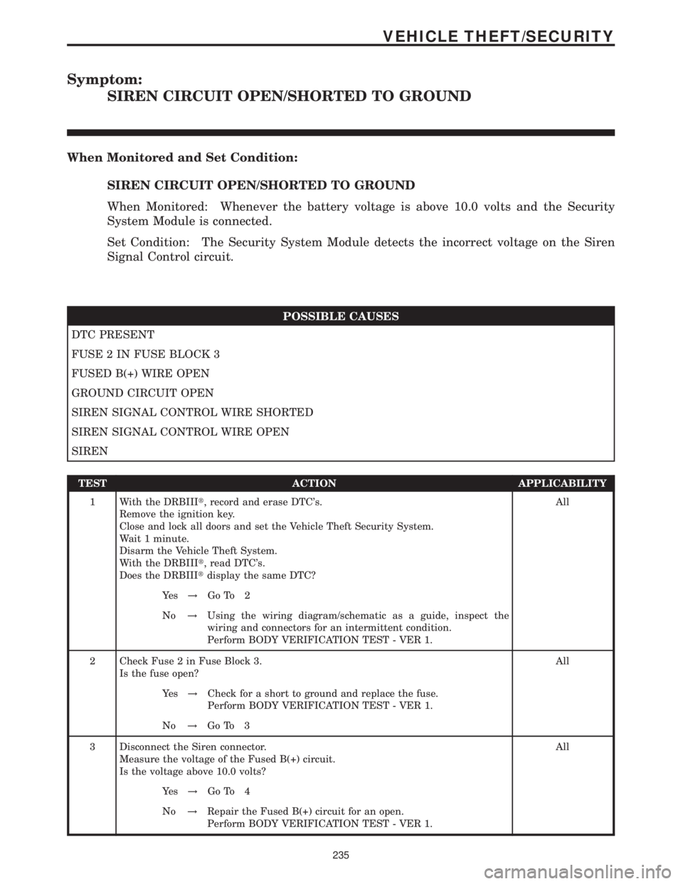
Symptom:
SIREN CIRCUIT OPEN/SHORTED TO GROUND
When Monitored and Set Condition:
SIREN CIRCUIT OPEN/SHORTED TO GROUND
When Monitored: Whenever the battery voltage is above 10.0 volts and the Security
System Module is connected.
Set Condition: The Security System Module detects the incorrect voltage on the Siren
Signal Control circuit.
POSSIBLE CAUSES
DTC PRESENT
FUSE 2 IN FUSE BLOCK 3
FUSED B(+) WIRE OPEN
GROUND CIRCUIT OPEN
SIREN SIGNAL CONTROL WIRE SHORTED
SIREN SIGNAL CONTROL WIRE OPEN
SIREN
TEST ACTION APPLICABILITY
1 With the DRBIIIt, record and erase DTC's.
Remove the ignition key.
Close and lock all doors and set the Vehicle Theft Security System.
Wait 1 minute.
Disarm the Vehicle Theft System.
With the DRBIIIt, read DTC's.
Does the DRBIIItdisplay the same DTC?All
Ye s!Go To 2
No!Using the wiring diagram/schematic as a guide, inspect the
wiring and connectors for an intermittent condition.
Perform BODY VERIFICATION TEST - VER 1.
2 Check Fuse 2 in Fuse Block 3.
Is the fuse open?All
Ye s!Check for a short to ground and replace the fuse.
Perform BODY VERIFICATION TEST - VER 1.
No!Go To 3
3 Disconnect the Siren connector.
Measure the voltage of the Fused B(+) circuit.
Is the voltage above 10.0 volts?All
Ye s!Go To 4
No!Repair the Fused B(+) circuit for an open.
Perform BODY VERIFICATION TEST - VER 1.
235
VEHICLE THEFT/SECURITY
Page 251 of 2305

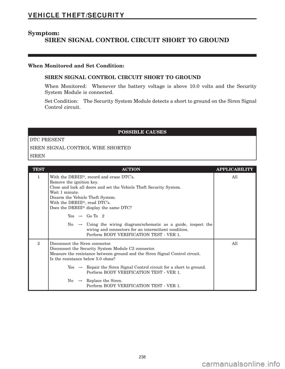
Symptom:
SIREN SIGNAL CONTROL CIRCUIT SHORT TO GROUND
When Monitored and Set Condition:
SIREN SIGNAL CONTROL CIRCUIT SHORT TO GROUND
When Monitored: Whenever the battery voltage is above 10.0 volts and the Security
System Module is connected.
Set Condition: The Security System Module detects a short to ground on the Siren Signal
Control circuit.
POSSIBLE CAUSES
DTC PRESENT
SIREN SIGNAL CONTROL WIRE SHORTED
SIREN
TEST ACTION APPLICABILITY
1 With the DRBIIIt, record and erase DTC's.
Remove the ignition key.
Close and lock all doors and set the Vehicle Theft Security System.
Wait 1 minute.
Disarm the Vehicle Theft System.
With the DRBIIIt, read DTC's.
Does the DRBIIItdisplay the same DTC?All
Ye s!Go To 2
No!Using the wiring diagram/schematic as a guide, inspect the
wiring and connectors for an intermittent condition.
Perform BODY VERIFICATION TEST - VER 1.
2 Disconnect the Siren connector.
Disconnect the Security System Module C2 connector.
Measure the resistance between ground and the Siren Signal Control circuit.
Is the resistance below 5.0 ohms?All
Ye s!Repair the Siren Signal Control circuit for a short to ground.
Perform BODY VERIFICATION TEST - VER 1.
No!Replace the Siren.
Perform BODY VERIFICATION TEST - VER 1.
238
VEHICLE THEFT/SECURITY
Page 257 of 2305

Verification Tests
ABS VERIFICATION TEST - VER 1 APPLICABILITY
1. Turn the ignition off.
2. Connect all previously disconnected components and connectors.
3. Ensure all accessories are turned off and the battery is fully charged.
4. Ensure that the Ignition is on, and with the DRBIII, erase all Diagnostic Trouble Codes from
ALL modules. Start the engine and allow it to run for 2 minutes and fully operate the system
that was malfunctioning.
5. Turn the ignition off and wait 5 seconds. Turn the ignition on and using the DRBIII, read
DTC's from ALL modules.
6. If any Diagnostic Trouble Codes are present, return to Symptom list and troubleshoot new
or recurring symptom.
7. NOTE: If the CAB/HCU was replaced, ensure the CAB has been initialized
8. NOTE: If the SKREEM or ECM was replaced, refer to the service information for
proper programming procedures.
9. NOTE: For Sensor Circuit/Signal and Pump Motor faults, the CAB must sense all 4
wheels at 12 km/h (8 mph) before it will extinguish the ABS Indicator.
10. If there are no DTC's present after turning ignition on, road test the vehicle for at least 5
minutes. Perform several antilock braking stops.
11. CAUTION: Ensure braking capability is available before road testing.
12. Again, with the DRBIIItread DTC's. If any DTC's are present, return to Symptom list.
13. If there are no Diagnostic Trouble Codes (DTC's) present, and the customer's concern can
no longer be duplicated, the repair is complete.
Are any DTC's present or is the original concern still present?All
Ye s!Repair is not complete, refer to appropriate symptom.
No!Repair is complete.
AIRBAG VERIFICATION TEST - VER 1 APPLICABILITY
1. Remove any special tools or jumper wires and reconnect all previously disconnected
components - except the Battery.
2. WARNING: TO AVOID PERSONAL INJURY OR DEATH, TURN THE IGNITION ON,
THEN RECONNECT THE BATTERY.
3. Connect the DRBIIItto the Data Link Connector - use the most current software available.
4. Use the DRBIIItand erase the stored codes in all airbag system modules.
5. Turn the ignition off, and wait 15 seconds, then turn the ignition on.
6. Wait one minute, and read active codes and if there are none present read the stored codes.
7. Note: If equipped with Airbag On - Off switch, read the DTC's in all switch positions.
8. Note: Read the DTC's in all airbag system related modules.
9. If the DRBIIItshows any active or stored codes, return to the Symptom list and follow path
specified for that trouble code. If no active or stored codes are present, the repair is complete.
Are any DTC's present or is the original condition still present?All
YES
Repair is not complete, refer to appropriate symptom list.
NO
Repair is complete.
244
VERIFICATION TESTS
Page 258 of 2305

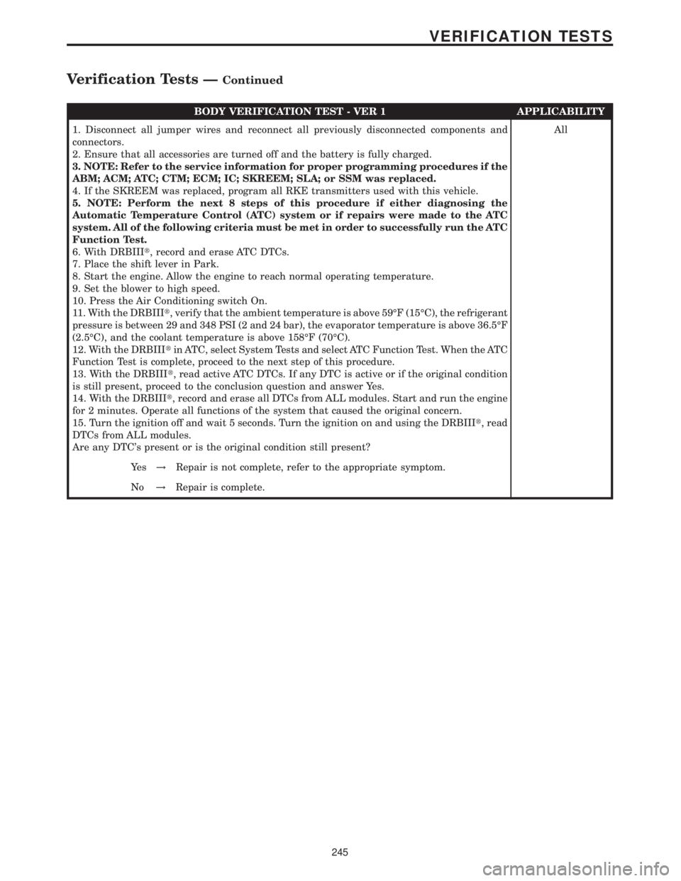
BODY VERIFICATION TEST - VER 1 APPLICABILITY
1. Disconnect all jumper wires and reconnect all previously disconnected components and
connectors.
2. Ensure that all accessories are turned off and the battery is fully charged.
3. NOTE: Refer to the service information for proper programming procedures if the
ABM; ACM; ATC; CTM; ECM; IC; SKREEM; SLA; or SSM was replaced.
4. If the SKREEM was replaced, program all RKE transmitters used with this vehicle.
5. NOTE: Perform the next 8 steps of this procedure if either diagnosing the
Automatic Temperature Control (ATC) system or if repairs were made to the ATC
system. All of the following criteria must be met in order to successfully run the ATC
Function Test.
6. With DRBIIIt, record and erase ATC DTCs.
7. Place the shift lever in Park.
8. Start the engine. Allow the engine to reach normal operating temperature.
9. Set the blower to high speed.
10. Press the Air Conditioning switch On.
11. With the DRBIIIt, verify that the ambient temperature is above 59ÉF (15ÉC), the refrigerant
pressure is between 29 and 348 PSI (2 and 24 bar), the evaporator temperature is above 36.5ÉF
(2.5ÉC), and the coolant temperature is above 158ÉF (70ÉC).
12. With the DRBIIItin ATC, select System Tests and select ATC Function Test. When the ATC
Function Test is complete, proceed to the next step of this procedure.
13. With the DRBIIIt, read active ATC DTCs. If any DTC is active or if the original condition
is still present, proceed to the conclusion question and answer Yes.
14. With the DRBIIIt, record and erase all DTCs from ALL modules. Start and run the engine
for 2 minutes. Operate all functions of the system that caused the original concern.
15. Turn the ignition off and wait 5 seconds. Turn the ignition on and using the DRBIIIt, read
DTCs from ALL modules.
Are any DTC's present or is the original condition still present?All
Ye s!Repair is not complete, refer to the appropriate symptom.
No!Repair is complete.
245
VERIFICATION TESTS
Verification Tests ÐContinued
Page 259 of 2305

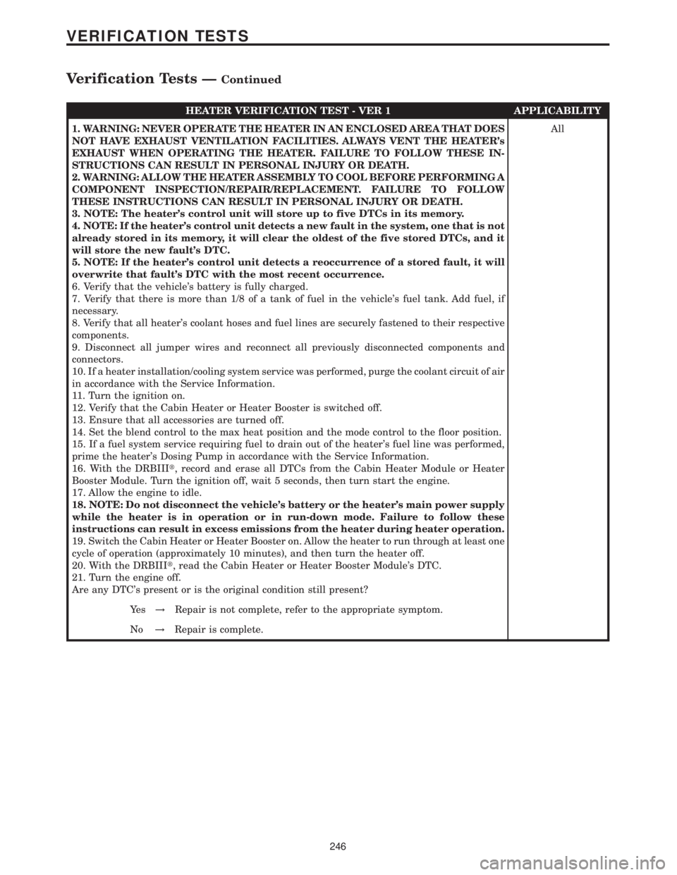
HEATER VERIFICATION TEST - VER 1 APPLICABILITY
1. WARNING: NEVER OPERATE THE HEATER IN AN ENCLOSED AREA THAT DOES
NOT HAVE EXHAUST VENTILATION FACILITIES. ALWAYS VENT THE HEATER's
EXHAUST WHEN OPERATING THE HEATER. FAILURE TO FOLLOW THESE IN-
STRUCTIONS CAN RESULT IN PERSONAL INJURY OR DEATH.
2. WARNING: ALLOW THE HEATER ASSEMBLY TO COOL BEFORE PERFORMING A
COMPONENT INSPECTION/REPAIR/REPLACEMENT. FAILURE TO FOLLOW
THESE INSTRUCTIONS CAN RESULT IN PERSONAL INJURY OR DEATH.
3. NOTE: The heater's control unit will store up to five DTCs in its memory.
4. NOTE: If the heater's control unit detects a new fault in the system, one that is not
already stored in its memory, it will clear the oldest of the five stored DTCs, and it
will store the new fault's DTC.
5. NOTE: If the heater's control unit detects a reoccurrence of a stored fault, it will
overwrite that fault's DTC with the most recent occurrence.
6. Verify that the vehicle's battery is fully charged.
7. Verify that there is more than 1/8 of a tank of fuel in the vehicle's fuel tank. Add fuel, if
necessary.
8. Verify that all heater's coolant hoses and fuel lines are securely fastened to their respective
components.
9. Disconnect all jumper wires and reconnect all previously disconnected components and
connectors.
10. If a heater installation/cooling system service was performed, purge the coolant circuit of air
in accordance with the Service Information.
11. Turn the ignition on.
12. Verify that the Cabin Heater or Heater Booster is switched off.
13. Ensure that all accessories are turned off.
14. Set the blend control to the max heat position and the mode control to the floor position.
15. If a fuel system service requiring fuel to drain out of the heater's fuel line was performed,
prime the heater's Dosing Pump in accordance with the Service Information.
16. With the DRBIIIt, record and erase all DTCs from the Cabin Heater Module or Heater
Booster Module. Turn the ignition off, wait 5 seconds, then turn start the engine.
17. Allow the engine to idle.
18. NOTE: Do not disconnect the vehicle's battery or the heater's main power supply
while the heater is in operation or in run-down mode. Failure to follow these
instructions can result in excess emissions from the heater during heater operation.
19. Switch the Cabin Heater or Heater Booster on. Allow the heater to run through at least one
cycle of operation (approximately 10 minutes), and then turn the heater off.
20. With the DRBIIIt, read the Cabin Heater or Heater Booster Module's DTC.
21. Turn the engine off.
Are any DTC's present or is the original condition still present?All
Ye s!Repair is not complete, refer to the appropriate symptom.
No!Repair is complete.
246
VERIFICATION TESTS
Verification Tests ÐContinued
Page 322 of 2305

1.0 INTRODUCTION
The procedures contained in this manual include
all the specifications, instructions, and graphics
needed to diagnose the Sprinter Chassis system
problems: Bosch 5.7 ABS/ESP/TCS (ASR) Braking
System. The diagnostics in this manual are based
on the failure condition or symptom being present
at time of diagnosis.
Please follow the recommendations below when
choosing your diagnostic path.
1. First make sure the DRBIIItis communicating
with the vehicle system being diagnosed. If the
DRBIIItdisplays a ``No Response'' condition, you
must diagnose that first.
2. Read DTC's (diagnostic trouble codes) with the
DRBIIIt.
3. If no DTC's are present, identify the customer
complaint.
4. Once the DTC or customer complaint is iden-
tified locate the matching test in the Table of
Contents and begin to diagnose the system.
All component location views are in Section 8.0.
All connector pinouts are in Section 9.0. All sche-
matics are in Section 10.0.
When repairs are required, refer to the appropri-
ate service manual for the proper removal and
repair procedure.
Diagnostic procedures change every year. New
diagnostic systems may be added; carryover sys-
tems maybe enhanced. READ THIS MANUAL BE-
FORE TRYING TO DIAGNOSE A VEHICLE DI-
AGNOSTIC TROUBLE CODE. It is recommended
that you review the entire manual to become famil-
iar with all new and changed diagnostic procedures.
This manual reflects many suggested changes
from readers of past issues. After using this man-
ual, if you have any comments or recommendations,
please fill out the form at the back of the manual
and mail it back.
1.1 SYSTEM COVERAGE
This diagnostic procedure manual covers the An-
tilock Braking System (ABS), the Electronic Stabil-
ity Program (ESP) and the Traction Control System
(TCS) found on the Sprinter.
1.2 SIX-STEP TROUBLESHOOTING
PROCEDURE
Diagnosis of the Antilock Brake Systems is done
in six basic steps:
²Verification of complaint
²Verification of any related symptoms
²Symptom analysis
²Problem isolation
²Repair of isolated problem
²Verification of proper operation
2.0 INDENTIFICATION OF
SYSTEM
The Bosch 5.7 system can be identified by the 42
way Controller Antilock Brake (CAB), Hydraulic
Control Unit (HCU) and Pump Motor being an
integral electronic/hydraulic unit mounted below
the Master Cylinder with four Wheel Speed Sen-
sors, one at each wheel.
Vehicles with the Traction Control System (TCS/
ASR) can be identified by the presence of the
Traction Control System Switch (TCCS) located on
the center instrument panel.
Vehicles with Electronic Stability Program (ESP)
can be identified by the presence of the Steering
Angle Sensor and the Lateral Acceleration/Yaw
Sensor.
3.0 SYSTEM DESCRIPTION AND
FUNCTIONAL OPERATION
3.1 ESP
The ESP system consists of the electronic control/
hydraulic unit, steering angle sensor, lateral
acceleration/yaw sensor and wheel speed sensors.
When the vehicle is in a turn, the ESP looks at the
steering wheel angle sensor value and monitors the
wheel speed of the inner and outer wheels to ensure
the values are plausible. The steering angle sensor
also measures the speed at which the steering
wheel is turned.
The ESP control module is very similar to the
ABS/ASR module. The ESP is comprised of several
other systems, namely theHBA, ABS, TCS (ASR),
EBDandFZRsystems.
3.2 ABS
The Controller Antilock Brake (CAB) is used to
monitor wheel speeds and modulates (controls) hy-
draulic pressure in each brake channel. The modu-
lated hydraulic pressure is used to prevent wheel
lock up during braking and maintain vehicle stabil-
ity. The CAB also provides a vehicle speed signal
(VSS) to the Electronic Control Module (ECM).
During a non-ABS stop, the system functions as a
standard braking system. The CAB uses special
sortware that monitors the wheel speed(s) and
when certain criteria are met, the software will
1
GENERAL INFORMATION
Page 325 of 2305

read opposite switch states.Note: The BS and
BLS are in the same switch housing.
BRAKE LAMP SWITCH (BLS):This switch pre-
pares the CAB for a possible antilock event. The
CAB uses an output state voltage from the BLS
when the brake pedal is either depressed/released.
The Fused Ignition Switch Output circuit supplies
12 volts to the BLS. A depressed brake pedal will
close the BLS circuit and the BLS Output circuit
supplies 12 volts at the CAB. When the driver
releases the brake pedal, the BLS Output circuit
voltage drops to 0 volts and the CAB senses the
brake pedal state. This tells the CAB what position
the brake pedal is currently in to make an ABS
event possible. When using the DRBIIItin Inputs/
Outputs, the BS and BLS will read opposite switch
states.Note: The BS and BLS are in the same
switch housing.
TRACTION CONTROL SYSTEM SWITCH
(TCSS):This switch signals the CAB to either turn
ON or OFF the TCS. The driver can toggle the
TCSS, which receives 12 volts from the D (+) Relay
Output circuit. Depending on the position of the
TCSS, open or closed, the CAB receives the TCSS
state voltage on the TCS Switch Sense circuit.
When 12 volts are applied to the TCS Switch Sense
circuit, the TCS is OFF. When no voltage is present,
the TCS is ON.
WHEEL SPEED SENSORS AND TONE
WHEELS:The Bosch 5.7 system uses one passive
WSS on each wheel. The sensor measures the wheel
speed by monitoring a rotating tone wheel. As the
teeth of the tone wheel move through the magnetic
field of the sensor an AC voltage and amperage is
generated. This signal frequency increases or de-
creases proportionally to the speed of the wheel.
The CAB monitors this signal to check for a sudden
change in single or multiple wheel decelerations. If
the deceleration of one or more wheels is not within
a predetermined amount, the CAB takes control for
antilock action through the HCU. Each WSS has a
magnetic inductive pick up coil (WSS) that is
mounted to a fixed component. There is an air gap
between the tone wheel and the speed sensor as-
sembly. Diagnostically, the coils of the Wheel Speed
Sensors have the same amount of resistance. When
measured across the CAB harness connector termi-
nals, the resistance should be between 1100 - 1800
ohms. Refer to service manual for WSS replacement
and air gap specifications.
Correct ABS operation is dependent on Tone
Wheel speed signal from the WSS. The vehicle
wheels and tires should all be the same size and
type to get accurate signals. In addition, all tires
should be at recommended tire pressures.3.7.5 SELF TESTS
The system software includes several self tests
that are performed every time the ignition is turned
on and the vehicle is driven. Some of the self tests
occur immediately, while others occur under normal
driving conditions while not in antilock operation.
The CAB checks continuously for a missing or
erratic WSS signals/circuits, tone wheels, solenoids,
pump motor or solenoid relay by performing several
tests such as: dynamic, static, ohmic, voltage drop,
and timed response. If any component exhibits a
fault during testing, the CAB will request to illumi-
nate the ABS and TCS warning indicators.
As an additional check of the ESP system, a road
test procedure is available on the DRBIIIt. This
test should be carried out when any ESP component
is replaced in order to ensure proper function. Since
the wheel speed sensors are required inputs to the
ESP, this test should also be performed if the wheel
speed sensors are replaced.
First, the brakes are applied with the vehicle
stationary. Then, the vehicle is driven at approxi-
mately 6 MPH. The driver has to make left and
right turns, with a minimum 90 degree steering
turning angle. If the indicator lamp goes out, every-
thing is in order. If the lamp remains illuminated,
the DRBIIItwill display the fault codes that are
causing the test to fail. The road test function is set
in the ESP control module, and can only be deacti-
vated once there are no more fault codes detected.
The Steering Angle Sensor must be initialized. A
procedure is carried out using the DRBIIItto
ensure that the module detects the exact position of
the sensor. The sensor must be calibrated any time
wheel alignment is changed, the steering column is
removed and re-installed, or the sensor is replaced.
3.8 USING THE DRBIIIT
Refer to the DRBIIItuser 's guide for instructions
and assistance with reading diagnostic trouble
codes, erasing diagnostic trouble codes and other
DRBIIItfunctions.
3.9 DRBIIITERROR MESSAGES
Under normal operation, the DRBIIItwill dis-
play one of only two error messages:
Ð User-Requested WARM Boot or User-Requested
COLD Boot.
If the DRBIIItshould display any other error
message, record the entire display and call the
STAR Center for information and assistance. This
is a sample of such an error message display:
4
GENERAL INFORMATION
Page 326 of 2305

ver: 2.14
date: 26 Jul93
file: key_iff.cc
date: Jul 26 1993
line: 548
err: 0x1
User-Requested COLD Boot
Press MORE to switch between this display
and the application screen.
Press F4 when done noting information.
3.9.1 DRBIIITDOES NOT POWER UP
(BLANK SCREEN)
If the LED's do not light or no sound is emitted at
start up, check for loose cable connections or a bad
cable. Check the vehicle battery voltage (data link
16-way connector cavity 16). A minimum of 11 volts
is required to adequately power the DRBIIIt. Also
check for a good ground at DLC.
If all connections are proper between the
DRBIIItand the vehicle or other devices, and the
vehicle battery is fully charged, an inoperative
DRBIIItmay be the result or a faulty cable or
vehicle wiring.
3.9.2 DISPLAY IS NOT VISIBLE
Low temperatures will affect the visibility of the
display. Adjust the contrast to compensate for this
condition.
4.0 DISCLAIMERS, SAFETY,
WARNINGS
4.1 DISCLAIMERS
All information, illustrations, and specifications
contained in this manual are based on the latestinformation available at the time of publication.
The right is reserved to make changes at any time
without notice.
4.2 SAFETY
4.2.1 TECHNICIAN SAFETY INFORMATION
WARNING: ENGINES PRODUCE CARBON
MONOXIDE THAT IS ODORLESS, CAUSES
SLOWER REACTION TIME, AND CAN LEAD
TO SERIOUS INJURY. WHEN THE ENGINE IS
OPERATING, KEEP SERVICE AREAS WELL
VENTILATED OR ATTACH THE VEHICLE
EXHAUST SYSTEM TO THE SHOP EXHAUST
REMOVAL SYSTEM.
Set the parking brake and block the wheels before
testing or repairing the vehicle. It is especially
important to block the wheels on front-wheel drive
vehicles; the parking brake does not hold the front
drive wheels.
When servicing a vehicle, always wear eye pro-
tection, and remove any metal jewelry such as
watchbands or bracelets that might make an inad-
vertent electrical contact.
When diagnosing an antilock brake or adjustable
pedals system problem, it is important to follow
approved procedures where applicable. These pro-
cedures can be found in the service manual. Follow-
ing these procedures is very important to safety of
individuals performing diagnostic tests.
4.2.2 VEHICLE PREPARATION FOR
TESTING
Make sure the vehicle being tested has a fully
charged battery. If it does not, false diagnostic codes
or error messages may occur.
4.2.3 SERVICING SUB-ASSEMBLIES
Some components of the antilock brake and trac-
tion control are intended to be serviced in assembly
only. Attempting to remove or repair certain sub-
components may result in personal injury and/or
improper system operation. Only those components
with approved repair and installation procedures in
the service manual should be serviced.
5
GENERAL INFORMATION