Page 250 of 2305

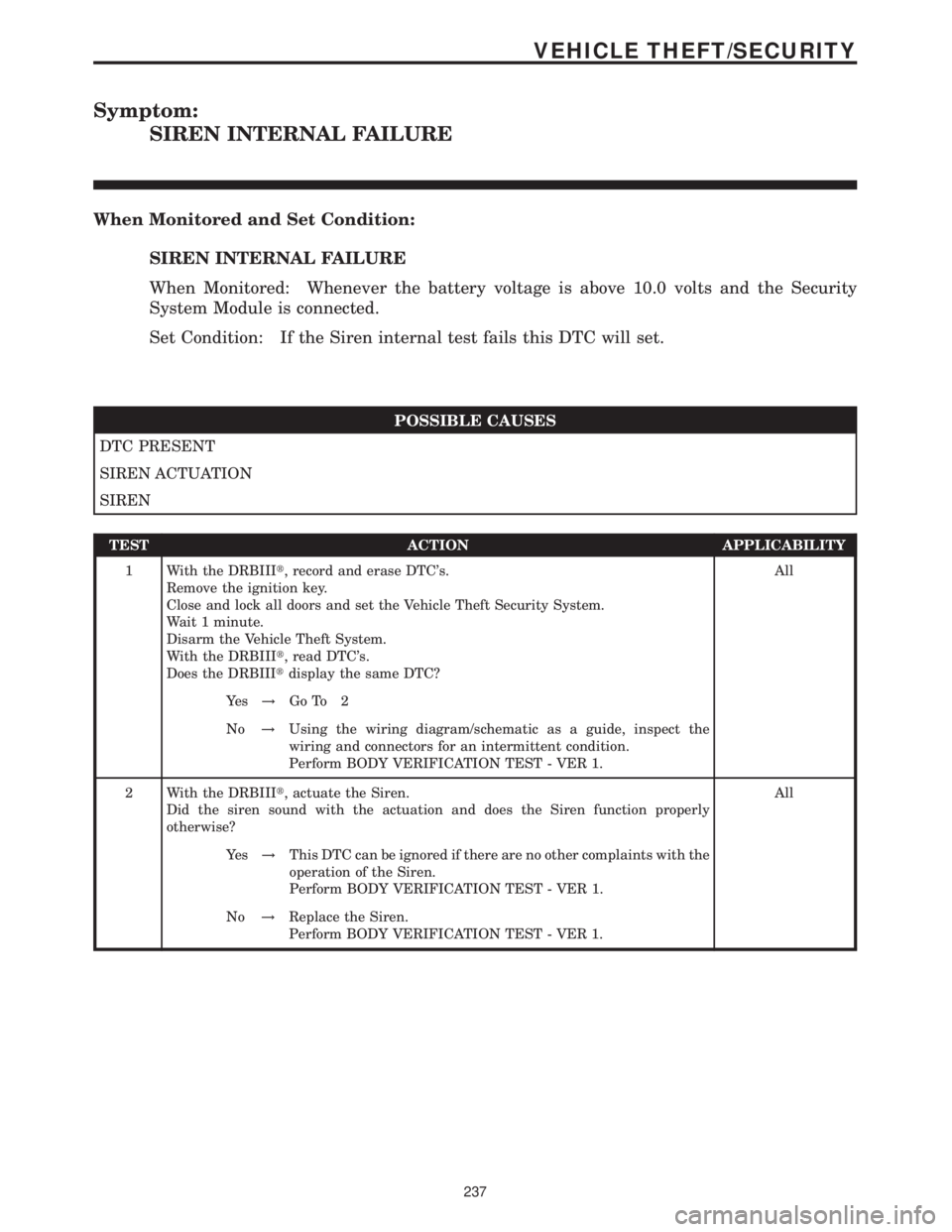
Symptom:
SIREN INTERNAL FAILURE
When Monitored and Set Condition:
SIREN INTERNAL FAILURE
When Monitored: Whenever the battery voltage is above 10.0 volts and the Security
System Module is connected.
Set Condition: If the Siren internal test fails this DTC will set.
POSSIBLE CAUSES
DTC PRESENT
SIREN ACTUATION
SIREN
TEST ACTION APPLICABILITY
1 With the DRBIIIt, record and erase DTC's.
Remove the ignition key.
Close and lock all doors and set the Vehicle Theft Security System.
Wait 1 minute.
Disarm the Vehicle Theft System.
With the DRBIIIt, read DTC's.
Does the DRBIIItdisplay the same DTC?All
Ye s!Go To 2
No!Using the wiring diagram/schematic as a guide, inspect the
wiring and connectors for an intermittent condition.
Perform BODY VERIFICATION TEST - VER 1.
2 With the DRBIIIt, actuate the Siren.
Did the siren sound with the actuation and does the Siren function properly
otherwise?All
Ye s!This DTC can be ignored if there are no other complaints with the
operation of the Siren.
Perform BODY VERIFICATION TEST - VER 1.
No!Replace the Siren.
Perform BODY VERIFICATION TEST - VER 1.
237
VEHICLE THEFT/SECURITY
Page 251 of 2305

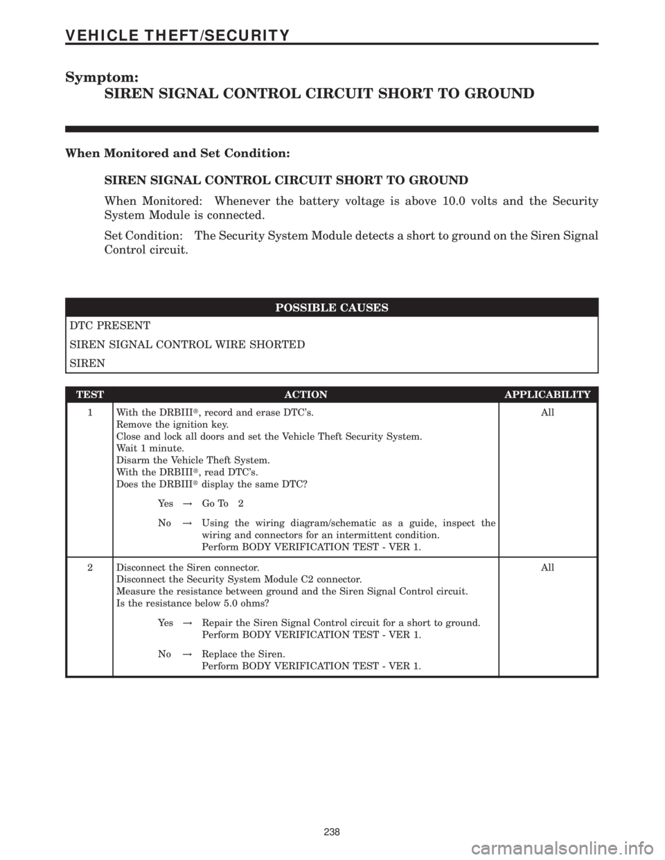
Symptom:
SIREN SIGNAL CONTROL CIRCUIT SHORT TO GROUND
When Monitored and Set Condition:
SIREN SIGNAL CONTROL CIRCUIT SHORT TO GROUND
When Monitored: Whenever the battery voltage is above 10.0 volts and the Security
System Module is connected.
Set Condition: The Security System Module detects a short to ground on the Siren Signal
Control circuit.
POSSIBLE CAUSES
DTC PRESENT
SIREN SIGNAL CONTROL WIRE SHORTED
SIREN
TEST ACTION APPLICABILITY
1 With the DRBIIIt, record and erase DTC's.
Remove the ignition key.
Close and lock all doors and set the Vehicle Theft Security System.
Wait 1 minute.
Disarm the Vehicle Theft System.
With the DRBIIIt, read DTC's.
Does the DRBIIItdisplay the same DTC?All
Ye s!Go To 2
No!Using the wiring diagram/schematic as a guide, inspect the
wiring and connectors for an intermittent condition.
Perform BODY VERIFICATION TEST - VER 1.
2 Disconnect the Siren connector.
Disconnect the Security System Module C2 connector.
Measure the resistance between ground and the Siren Signal Control circuit.
Is the resistance below 5.0 ohms?All
Ye s!Repair the Siren Signal Control circuit for a short to ground.
Perform BODY VERIFICATION TEST - VER 1.
No!Replace the Siren.
Perform BODY VERIFICATION TEST - VER 1.
238
VEHICLE THEFT/SECURITY
Page 257 of 2305

Verification Tests
ABS VERIFICATION TEST - VER 1 APPLICABILITY
1. Turn the ignition off.
2. Connect all previously disconnected components and connectors.
3. Ensure all accessories are turned off and the battery is fully charged.
4. Ensure that the Ignition is on, and with the DRBIII, erase all Diagnostic Trouble Codes from
ALL modules. Start the engine and allow it to run for 2 minutes and fully operate the system
that was malfunctioning.
5. Turn the ignition off and wait 5 seconds. Turn the ignition on and using the DRBIII, read
DTC's from ALL modules.
6. If any Diagnostic Trouble Codes are present, return to Symptom list and troubleshoot new
or recurring symptom.
7. NOTE: If the CAB/HCU was replaced, ensure the CAB has been initialized
8. NOTE: If the SKREEM or ECM was replaced, refer to the service information for
proper programming procedures.
9. NOTE: For Sensor Circuit/Signal and Pump Motor faults, the CAB must sense all 4
wheels at 12 km/h (8 mph) before it will extinguish the ABS Indicator.
10. If there are no DTC's present after turning ignition on, road test the vehicle for at least 5
minutes. Perform several antilock braking stops.
11. CAUTION: Ensure braking capability is available before road testing.
12. Again, with the DRBIIItread DTC's. If any DTC's are present, return to Symptom list.
13. If there are no Diagnostic Trouble Codes (DTC's) present, and the customer's concern can
no longer be duplicated, the repair is complete.
Are any DTC's present or is the original concern still present?All
Ye s!Repair is not complete, refer to appropriate symptom.
No!Repair is complete.
AIRBAG VERIFICATION TEST - VER 1 APPLICABILITY
1. Remove any special tools or jumper wires and reconnect all previously disconnected
components - except the Battery.
2. WARNING: TO AVOID PERSONAL INJURY OR DEATH, TURN THE IGNITION ON,
THEN RECONNECT THE BATTERY.
3. Connect the DRBIIItto the Data Link Connector - use the most current software available.
4. Use the DRBIIItand erase the stored codes in all airbag system modules.
5. Turn the ignition off, and wait 15 seconds, then turn the ignition on.
6. Wait one minute, and read active codes and if there are none present read the stored codes.
7. Note: If equipped with Airbag On - Off switch, read the DTC's in all switch positions.
8. Note: Read the DTC's in all airbag system related modules.
9. If the DRBIIItshows any active or stored codes, return to the Symptom list and follow path
specified for that trouble code. If no active or stored codes are present, the repair is complete.
Are any DTC's present or is the original condition still present?All
YES
Repair is not complete, refer to appropriate symptom list.
NO
Repair is complete.
244
VERIFICATION TESTS
Page 263 of 2305
8.4 CLOCKSPRING
8.5 SEAT BELT TENSIONER
8.6 HEATING & A/C
8.6.1 AUTOMATIC TEMPERATURE CONTROL (ATC) SYSTEM COMPONENTS
C
O
M
P
O
N
E
N
T
L
O
C
A
T
I
O
N
S
250
COMPONENT LOCATIONS
Page 265 of 2305
8.7 INSTRUMENT CLUSTER
8.7.1 AMBIENT TEMPERATURE SENSOR
8.8 POWER DOOR LOCKS/RKE
8.8.1 CENTRAL TIMER MODULE
C
O
M
P
O
N
E
N
T
L
O
C
A
T
I
O
N
S
252
COMPONENT LOCATIONS
Page 266 of 2305
8.8.2 SENTRY KEY REMOTE ENTRY MODULE
8.8.3 DOOR LOCK MOTOR/AJAR SWITCH
8.8.4 CONTACT PLATES
C
O
M
P
O
N
E
N
T
L
O
C
A
T
I
O
N
S
253
COMPONENT LOCATIONS
Page 267 of 2305
8.8.5 DOOR LOCK MOTOR/AJAR SWITCH CONNECTORS
8.9 VEHICLE THEFT SECURITY SYSTEM
8.9.1 SECURITY SYSTEM MODULE
8.9.2 INTRUSION SENSORS
C
O
M
P
O
N
E
N
T
L
O
C
A
T
I
O
N
S
254
COMPONENT LOCATIONS
8.8 POWER DOOR LOCKS/RKE (Continued)
Page 272 of 2305

AUTOMATIC TEMPERATURE CONTROL MODULE C1 - BROWNCAV CIRCUIT FUNCTION
1 16RD/BL FUSED B(+)
2 18DG/RD (REST SYSTEM) CIRCULATION PUMP CONTROL
3 18BK/RD A/C AUXILIARY FAN RELAY HIGH SIDE CONTROL
4 16BL/YL HEATER BOOSTER MODE
5 18BR/VT WATER CYCLE VALVE CONTROL
6 20RD/BL 5 VOLT SUPPLY
7 18BK/YL K-IC/ATC/HBM/CHM
8 16RD/YL/WT FUSED D(+) RELAY OUTPUT
8 20BL/VT D(+) RELAY CONTROL
9 16GY/DG/RD LAMP DRIVER
10 16BL CABIN HEATER CONTROL
11 16BK/BL/WT RECIRCULATED AIR SOLENOID VALVE CONTROL
12 16BL/DG A/C COMPRESSOR CLUTCH CONTROL
13 18BR/DG EVAPORATOR TEMPERATURE SENSOR SIGNAL
14 - -
15 16BR GROUND
16 18BR/GY AIR OUTLET TEMPERATURE SENSOR SIGNAL
17 20DG/WT CAN C BUS (+)
18 18BR/BL SENSOR GROUND
19 20BR/RD REFRIGERANT PRESSURE SENSOR FEEDBACK
20 20DG CAN C BUS (-)
21 16BK/BL/DG FUSED IGNITION SWITCH OUTPUT
AUTOMATIC TEMPERATURE CONTROL MODULE C2CAV CIRCUIT FUNCTION
1 14BK/VT FAN STAGE 1 RELAY OUTPUT
1 12YL BLOWER MOTOR LOW DRIVER
2 12WT BLOWER MOTOR HIGH DRIVER
3 12WT/BK BLOWER MOTOR M1 DRIVER
4 12YL/BK BLOWER MOTOR M2 DRIVER
5 12RD/BL FUSED B(+)
AUXILIARY HEATER CONTROLCAV CIRCUIT FUNCTION
1 16GY/DG/RD LAMP DRIVER
2- -
3 16RD/YL FUSED B(+)
4- -
5- -
6- -
7 16YL CABIN HEATER CONTROL
8- -
9- -
10 16BR GROUND
BLOWER MOTOR RESISTOR BLOCKCAV CIRCUIT FUNCTION
1 12YL/BK BLOWER MOTOR M2 DRIVER
2 12YL BLOWER MOTOR LOW DRIVER
3 12WT/BK BLOWER MOTOR M1 DRIVER
4 12DG BLOWER MOTOR HIGH DRIVER
C
O
N
N
E
C
T
O
R
P
I
N
O
U
T
S
259
CONNECTOR PINOUTS