2006 LAND ROVER FRELANDER 2 coolant level
[x] Cancel search: coolant levelPage 1115 of 3229
Publi s hed: 11-May-2011
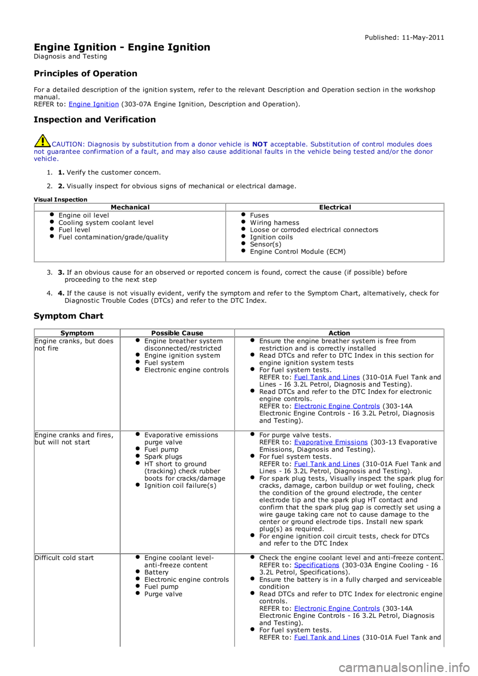
Engine Ignition - Engine Ignition
Diagnosi s and Tes ti ng
Principles of Operation
For a detail ed descripti on of the ignit ion s yst em, refer to the relevant Des cri pti on and Operati on s ect ion i n t he works hopmanual.REFER to: Engine Ignit ion (303-07A Engi ne Igni ti on, Des cript ion and O perati on).
Inspection and Verification
CAUTION: Di agnos is by s ubs ti tut ion from a donor vehicle is NO T acceptabl e. Subs ti tut ion of cont rol modules doesnot guarant ee confirmat ion of a faul t, and may als o caus e addit ional fault s i n t he vehi cl e being t est ed and/or t he donorvehi cl e.
1. Verify t he cus t omer concern.1.
2. Vis ually ins pect for obvious s igns of mechani cal or electrical damage.2.
Visual InspectionMechanicalElectrical
Engine oil l evelCooli ng sys t em cool ant levelFuel l evelFuel contami nati on/grade/quali ty
Fus esW iring harnes sLoos e or corroded electrical connect orsIgnit ion coil sSens or(s)Engine Cont rol Modul e (ECM)
3. If an obvious cause for an obs erved or report ed concern is found, correct t he caus e (if pos s ible) beforeproceeding t o t he next s t ep3.
4. If t he caus e is not vis ually evi dent , verify t he sympt om and refer t o t he Sympt om Chart, al ternat ively, check forDi agnos ti c Trouble Codes (DTCs) and refer t o t he DTC Index.4.
Symptom Chart
SymptomPossible CauseActionEngine cranks , but doesnot fi reEngine breat her sys temdis connected/res trict edEngine i gni ti on s ys t emFuel sys temElect ronic engine controls
Ens ure the engine breat her sys t em i s free fromres tricti on and is correctl y ins tal ledRead DTCs and refer t o DTC Index in t his s ecti on forengine ignit ion s ys tem tes tsFor fuel s yst em tes ts .REFER t o: Fuel Tank and Lines (310-01A Fuel Tank andLi nes - I6 3.2L Petrol, Diagnos is and Tes ti ng).Read DTCs and refer t o t he DTC Index for elect roni cengine cont rols .REFER t o: Electroni c Engi ne Control s (303-14AEl ect ronic Engi ne Cont rol s - I6 3.2L Pet rol, Di agnos isand Tes t ing).
Engine cranks and fires ,but wil l not s t artEvaporati ve emis s ionspurge val veFuel pumpSpark pl ugsHT short to ground(tracki ng) check rubberboots for cracks /damageIgni ti on coil fai lure(s )
For purge valve tes ts .REFER t o: Evaporat ive Emi s si ons (303-13 Evaporati veEmis s ions, Di agnos is and Tes t ing).For fuel s yst em tes ts .REFER t o: Fuel Tank and Lines (310-01A Fuel Tank andLi nes - I6 3.2L Petrol, Diagnos is and Tes ti ng).For s park pl ug tes ts , Vi suall y ins pect t he s park pl ug forcracks , damage, carbon buil dup or wet fouling, checkthe condi ti on of the ground electrode, t he cent erel ect rode t ip and the s park pl ug HT contact andconfi rm t hat t he s park pl ug gap is correct ly set us ing awire gauge taking care not t o cause damage to thecenter or ground el ect rode t ips . Ins tal l new s parkpl ug(s ) as required.For engine i gni ti on coi l ci rcuit t est s , check for DTCsand refer t o t he DTC Index
Di fficul t col d s t artEngine coolant level-anti -freeze contentBat teryElect ronic engine controlsFuel pumpPurge val ve
Check t he engi ne cool ant l evel and anti -freeze cont ent.REFER t o: Specificati ons (303-03A Engine Cool ing - I63.2L Petrol, Speci ficat ions).Ens ure the bat tery is i n a full y charged and s erviceabl econdit ionRead DTCs and refer t o DTC Index for electroni c enginecontrols .REFER t o: Electroni c Engi ne Control s (303-14AEl ect ronic Engi ne Cont rol s - I6 3.2L Pet rol, Di agnos isand Tes t ing).For fuel s yst em tes ts .REFER t o: Fuel Tank and Lines (310-01A Fuel Tank and
Page 1206 of 3229
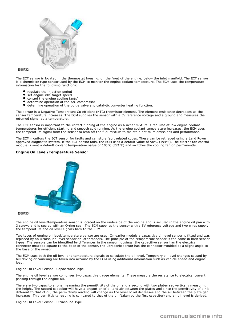
The ECT s ens or is locat ed i n t he thermost at hous ing, on t he front of the engine, below t he i nl et manifol d. The ECT s ens oris a t hermis t or type s ens or us ed by the ECM t o monit or the engine coolant t emperature. The ECM uses t he t emperatureinformat ion for the foll owi ng functi ons:
regulat e t he inject ion peri ods et engi ne idle target s peedcont rol t he engi ne cool ing fan(s )determine operat ion of t he A/C compres sordetermine operat ion of t he purge valve and catal yt ic convert er heat ing funct ion.
The s ens or is a Negat ive Temperat ure Co-efficient (NTC) thermis tor element . The element res is t ance decreas es as thes ens or t emperature increas es. The ECM suppli es the sens or wit h a 5V reference volt age and a ground and meas ures theret urned s ignal as a t emperature.
The ECT s ens or is important to the correct running of t he engi ne as a richer mixt ure i s required at low engi ne cool antt emperatures for efficient s tarti ng and s mooth cold running. As t he engi ne cool ant temperat ure i ncreas es , the ECM usest he temperat ure si gnal from the sens or to l ean off t he fuel mi xt ure to maint ai n optimum emis s ions and performance.
The ECM moni tors the ECT sens or for faul ts and can s t ore faul t rel at ed codes . These can be ret ri eved us ing a Land Roverapproved diagnos t ic s yst em. If the ECT sens or fail s, t he ECM us es a defaul t val ue of 90°C (194°F). The electric fan cont rolmodule i s s ent a default coolant temperat ure val ue of 105°C (221°F) and s wit ches t he cooling fan on permanent ly.
Engine Oil Level/Temperature Sensor
The engi ne oil l evel/t emperature s ens or is locat ed on t he unders ide of t he engi ne and is secured i n t he engi ne oil pan wi th3 s crews and i s s eal ed wi th an O-ring s eal. The ECM suppli es the s ens or wit h a 5V reference volt age and two wires s uppl yt he temperat ure and oi l level si gnal s back t o t he ECM.
Two t ypes of engine oi l level /t emperat ure s ensor are us ed. On earli er model s a capacit ive oi l level s ens or i s fit ted and wasrepl aced by an ul trasound l evel s ens or on l at er models . The principl e of the temperat ure s ens or i s t he s ame in bot h s ens ort ypes . The sens ors can be i dent ified by di fferences in t he s ens or housi ngs ; t he capacit ive s ensor has t he electricalconnector moulded s quare t o t he bas e of the s ens or, t he ult ras oni c s ens or has the connect or moulded at a s li ght angle tot he bas e of t he s ens or.
The ECM us es both the oi l l evel and t emperature s ignals t o calculat e t he oil level. Temporary oil level changes caus ed byhil l driving or cornering are taken i nt o account by t he ECM us ing addit ional informat ion s uch as vehi cl e s peed and engi neload.
Engi ne Oi l Level Sens or - Capacit ance Type
The engi ne oil l evel s ens or compris es t wo capaci ti ve gauge el ement s . Thes e meas ure the resi s tance to elect rical currentpass i ng through t he engine oi l.
There are t wo capacit ors , one meas uring t he permit ti vi ty of t he oil and a second with t wo pl at es s et verti cal ly meas uri ngt he hei ght . The s econd capaci tor wil l have a proport ion of oil and ai r bet ween t he plates and s i nce t he permit ti vi ty of ai r isdifferent t o t hat of oi l, t he permi tt ivit y readi ng wil l change as t he level of oi l decreas es and the ai r between t he plat e gapincreas es. This permi tt ivit y readi ng is compared t o t hat of the oi l (t aken by t he first capaci tor) and an oil level is derived.
Engi ne Oi l Level Sens or - Ult ras ound Type
Page 1239 of 3229
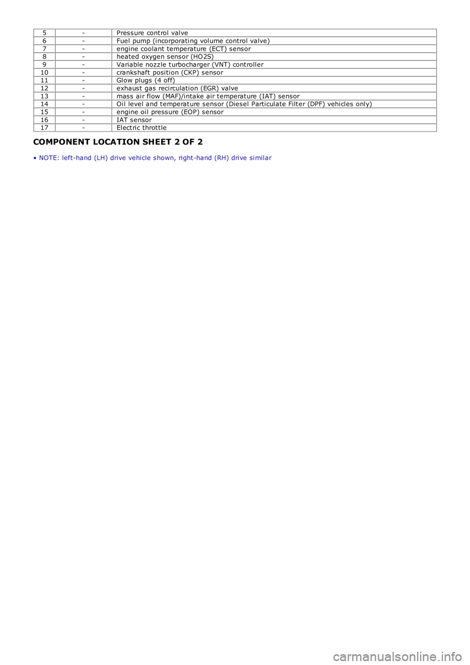
5-Pres s ure cont rol val ve
6-Fuel pump (i ncorporati ng vol ume control valve)
7-engine coolant temperature (ECT) s ens or8-heated oxygen s ens or (HO 2S)
9-Variable nozzle t urbocharger (VNT) cont roll er
10-cranks haft posi ti on (CKP) s ensor11-Gl ow plugs (4 off)
12-exhaus t gas reci rculati on (EGR) valve
13-mas s ai r fl ow (MAF)/i ntake air t emperat ure (IAT) s ens or14-Oi l level and t emperat ure s ens or (Dies el Parti cul ate Fi lt er (DPF) vehi cl es onl y)
15-engine oi l press ure (EOP) s ensor
16-IAT s ensor17-El ect ri c throt t le
COMPONENT LOCATION SHEET 2 OF 2
• NOTE: left-hand (LH) drive vehi cle s hown, ri ght -hand (RH) dri ve si mil ar
Page 1246 of 3229
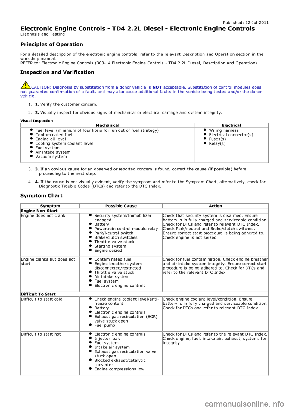
Publi shed: 12-Jul-2011
Electronic Engine Controls - TD4 2.2L Diesel - Electronic Engine Controls
Diagnosi s and Tes ti ng
Principles of Operation
For a detail ed descripti on of the el ect ronic engi ne cont rols , refer to the relevant Des cri pti on and Operati on s ect ion i n t heworks hop manual .REFER to: Elect ronic Engine Cont rols (303-14 El ect ronic Engine Cont rols - TD4 2.2L Di esel , Des cri pti on and Operati on).
Inspection and Verification
CAUTION: Di agnos is by s ubs ti tut ion from a donor vehicle is NO T acceptabl e. Subs ti tut ion of cont rol modules doesnot guarant ee confirmat ion of a faul t, and may als o caus e addit ional fault s i n t he vehi cl e being t est ed and/or t he donorvehi cl e.
1. Verify t he cus t omer concern.1.
2. Vis ually ins pect for obvious s igns of mechani cal or electrical damage and sys tem integrit y.2.
Visual InspectionMechanicalElectrical
Fuel l evel (mini mum of four lit ers for run out of fuel s t rategy)Contami nat ed fuelEngine oil l evelCooli ng sys t em cool ant levelFuel s ys temAir i ntake s yst emVacuum s ys t em
W i ri ng harnessElectrical connect or(s)Fus es (s )Relay(s )
3. If an obvious cause for an obs erved or report ed concern is found, correct t he caus e (if pos s ible) beforeproceeding t o t he next s t ep.3.
4. If t he caus e is not vis ually evi dent , verify t he sympt om and refer t o t he Sympt om Chart, al ternat ively, check forDi agnos ti c Trouble Codes (DTCs) and refer t o t he DTC Index.4.
Symptom Chart
SymptomPossible CauseAction
Engine Non-StartEngine does not crankSecurit y s yst em/Immobi li zerengagedBatt eryPowert rai n cont rol module relayPark/Neut ral s wit chBrake/cl ut ch s wit chesThrot tl e valve s tuckSt arti ng s yst emEngine s eized
Check t hat securi ty s ys tem is di sarmed. Ens urebat t ery i s in full y charged and s erviceabl e condi ti on.Check for DTCs and refer t o rel evant DTC Index.Check Park/neut ral and Brake/cl ut ch s wit ches .Ens ure correct s tart procedure is bei ng adhered to.Check engine i s not sei zed
Engine cranks but does nots tartContami nat ed fuelEngine breat her s ys temdis connected/res trictedThrot tl e valve s tuckAir i ntake s yst emFuel s ys temElectronic engine controls
Check for fuel cont aminati on. Check engi ne breat herand air int ake sys t em i nt egri ty. Ensure correct s tartprocedure is bei ng adhered to. Check for DTCs andrefer t o t he rel evant DTC Index
Difficult T o Start
Di fficul t t o s tart col dCheck engi ne coolant l evel/anti -freeze cont entBatt eryElectronic engine controlsExhaus t gas recircul ati on (EGR)valve s t uck openFuel pump
Check engine coolant level/condit ion. Ensurebat t ery i s in full y charged and s erviceabl e condi ti on.Check for DTCs and refer t o rel evant DTC Index
Di fficul t t o s tart hotElectronic engine controlsInjector leakFuel s ys temIntake air s ys temExhaus t gas recircul ati on val ves tuck openBlocked exhaus t/cat alyt icconverterEngine compres s ions low
Check for DTCs and refer t o t he rel evant DTC Index.Check engine, fuel, i ntake air, exhaus t, s ys tems forint egrit y
Page 1294 of 3229
W hen movi ng from a st andst il l, ups hi ft s can be pre-s el ect ed by making '+' s el ect ions wi th the s elect or l ever for thenumber of ups hifts requi red. The TCM t hen performs t he reques ted number of upshi ft s when appropri at e s hift points arereached. For exampl e; when moving off in 1s t gear, if 3 '+' s elect ions are made i n quick s ucces si on, t he TCM willautomat ically ups hift t hrough the gears to 4t h gear as t he vehi cl e accelerates , wit hout any furt her s electi ons bei ng made.
Cooling
Cooling mode is act ivated when t he TCM det ect s exces s ively hi gh trans mi s si on fl uid or engine coolant temperatures . W hent hi s mode i s act ive torque converter l ock-up is acti vat ed earl ier t o mi ni mi ze a further ris e in fl uid and/or engine coolantt emperature and ass i st flui d cool ing.
Hill Descent Control (HDC)
The HDC mode as s is t s t he ABS module i n cont rol li ng the downhil l speed of t he vehi cl e. W hen HDC i s acti ve, t he TCMs elect s t he mos t appropri at e gear for t he descent to maxi mi ze engi ne braking.
Maximum engi ne braking i s applied us i ng a s hift map which i nit iat es later ups hift s and earl y downshi ft s .
Cruise
W hen s peed cont rol i s act ivated, t he TCM receives a speed control acti ve mes s age on the hi gh s peed CAN bus . The TCMact ivat es a s peed cont rol map whi ch minimizes up and down s hifts .
Crui se mode is act ive when s peed cont rol is sel ect ed on and t he transmis s ion i s in drive 'D', s port 'S', HDC or Terrai nRespons e Gras s /gravel /s now program. Unique cruis e maps overri de the current mode t o provide a smoot h driving feel andmode resel ect ion.
Limp Home
If a transmis s ion faul t is det ect ed by t he TCM, the TCM adopt s a l imp home s trategy and a mes s age 'TRANSMISSIONFAULT LIMITED GEARS AVAILABLE' i s dis played in the mes s age cent er. If the fault has an effect on engi ne emis s ions , theMIL in the i nst rument clus t er wi ll als o be il luminat ed.
In li mp home mode, P, R and N functi ons operate normall y (i f the fault al lows t hes e s elect ions) and t he TCM locks t het ransmis s ion i n 3rd gear t o all ow t he dri ver t o t ake the vehicle to a Land Rover deal er or approved repai rer. Torqueconvert er lock-up i s dis abled and reverse-lock-out wil l not funct ion.
If the vehicle is s t opped and s ubsequentl y res tarted in t he li mp home mode condi ti on, t he TCM operat es normall y unti l thefaul t which caus ed t he condi ti on is det ect ed agai n.
Coast
Coast mode provides earli er downs hifts during coast ing dependant on out put shaft decelerat ion rate to improve driveabili tyand refinement by avoi ding negati ve to pos it ive driveli ne torque revers als t rans mi ssion during t he downshi ft s .
Fast Off Recognition
Fast off recogni ti on is act ivated when t he TCM det ect s t hat t he dri ver has releas ed the accel erat or pedal qui ckl y. This isdetected by the TCM monit oring for a high level of negat ive pedal angl e from ECM s ignals on t he high speed CAN bus . Ift hi s condi ti on is det ect ed, t he TCM hol ds the current gear rati o to allow the driver t o compl ete the manoeuvre wi thout t heneed for a downs hift. The mode can remain acti ve for a predet ermined lengt h of ti me or i f the driving s t yl e remainspass i ve.
Fast off recogni ti on mode as si s ts vehicle st abili ty and is us ed i n conjunct ion a lateral accel erat ion i nput duri ng corneri ng tomaint ain t he current gear unti l the corner is negot iated.
Uphill and Trailer
Uphill and t rai ler mode can be acti ve when the trans mi s si on is operat ing in normal, s port or Terrai n Res pons e modes .W hen t he vehicle i s pull ing a t rai ler or dri vi ng up an i ncl ine, the TCM det ects t he i ncreas ed res i st ance by monit oring enginet orque and s peed s i gnal s received from the ECM on the hi gh s peed CAN bus and als o t rans mis s ion out put s haft s peeds ens or s ignals . Uphi ll and t rai ler mode wi ll provide downs hift s t o prevent a drop in t rans mi ss i on torque out put andmaint ain driving force.
Downhill
Downhill mode can be act ive when t he t ransmis s ion i s operati ng in normal, s port or Terrain Res pons e modes . W hen t hevehi cl e i s descendi ng an i ncl ine t he TCM detect s a reducti on in res is t ance by moni toring engine t orque and s peed si gnal sreceived from the ECM on t he high s peed CAN bus and als o t rans mis s ion out put shaft speed s ensor s ignals . Downhill modeas si st s engine braki ng by s elect ing an appropriat e gear reduci ng the load required on t he brakes .
Wide Throttle
W i de open thrott le mode operates for part thrott le ups hifts and ki ck-down ups hifts . It provides cons i st ent wide opent hrott le ups hift performance under all driving condit ions. The full engine s peed range is used i n all driving modes ; normal ,s port, hi ll modes and Commands hi ft . Compens at ion i s used for delays (hydrauli c and electroni c) in gear change reques t togear change s tart to provi de s mooth changes and correct shi ft point correct ion.
Terrain Response
The Terrai n Res pons e s ys tem has a unique s et of shi ft maps for each of t he Terrai n Res pons e programs . Thes e programsoverri de exis ti ng modes; for exampl e when HDC is acti ve and the 'Sand', 'Mud and Ruts ' or 'Grass /Gravel/Snow' programsare sel ect ed, a specific Terrain Res ponse map is used, not the HDC mode s hift map detai led previ ous ly.
Page 1556 of 3229
Publi shed: 13-Jul-2011
Fuel Tank and Lines - I6 3.2L Petrol - Fuel Tank and Lines
Diagnosi s and Tes ti ng
Principles of Operation
For a detail ed descripti on of the fuel tank and l ines s ys t ems , refer t o t he rel evant Des cript ion and Operat ion s ecti on in theworks hop manual .REFER to: Fuel Tank and Lines (310-01A Fuel Tank and Lines - I6 3.2L Pet rol , Descri pti on and Operat ion).
Inspection and Verification
CAUTION: Di agnos is by s ubs ti tut ion from a donor vehicle is NO T acceptabl e. Subs ti tut ion of cont rol modules doesnot guarant ee confirmat ion of a faul t, and may als o caus e addit ional fault s i n t he vehi cl e being t est ed and/or t he donorvehi cl e.
• NOTE: For di agnos t ic purpos es the cyli nders are divided i nt o t wo banks: Bank 1 - Cyl inder numbers 1, 2 and 3. Bank 2 -Cylinders 4, 5 and 6
1. Verify t he cus t omer concern.1.
2. Vis ually ins pect for obvious s igns of mechani cal or electrical damage.2.
Visual Inspection
MechanicalElectricalFuel l eaksDamaged fuel l inesDamaged push connect fit t ingsFuel l evelFuel contami nati on/grade/quali tyDamaged fuel t ank fi ller pipe capDamaged fuel t ank fi ller pipe
FusesLoos e or corroded elect rical connect orsHarnes s esFuel Pump Dri ver Module (FPDM)Central Junct ion Box (CJB)Fuel pump relayEngine Control Modul e (ECM)
3. If an obvious cause for an obs erved or report ed concern is found, correct t he caus e (if pos s ible) beforeproceeding t o t he next s t ep.3.
4. If t he caus e is not vis ually evi dent , verify t he sympt om and refer t o t he Sympt om Chart, al ternat ively, check forDi agnos ti c Trouble Codes (DTCs) and refer t o t he DTC Index.4.
Symptom Chart
SymptomPossible CauseAction
Engine cranks , but does not fi reEngine breat her sys temdi sconnect ed/res trict edIgnit ion s yst emFuel sys temEl ect ronic engine controls
Ens ure t he engi ne breat her s ys tem is free fromres t ri ct ion and is correct ly i nst all edFor ignit ion s ys tem tes t s.REFER to: Engine Ignit ion (303-07A EngineIgni ti on, Di agnos is and Tes t ing).For fuel s ys t em t est s . Read DTCs and refer t oDTC Index in t his secti onFor elect roni c engi ne cont rol t es t s .REFER to: El ect ronic Engine Cont rols (303-14AElectronic Engine Controls - I6 3.2L Petrol ,Di agnos is and Tes ti ng).
Engine cranks and fires , but wil lnot s tartEvaporati ve emis s ionspurge val veFuel pumpSpark pl ugsIgnit ion coil fai lure(s )
For purge valve t est s .REFER to: Evaporati ve Emis s ions (303-13Evaporati ve Emis s ions, Di agnos is and Tes t ing).For fuel pump t es t s . Check for DTCs and refert o DTC Index in t his s ecti onFor ignit ion s ys tem tes t s.REFER to: Engine Ignit ion (303-07A EngineIgni ti on, Di agnos is and Tes t ing).
Di fficul t col d s t artCheck engi ne cool antl evel /anti -freeze cont entBat teryEl ect ronic engine controlsFuel pumpEvaporati ve emis s ionspurge val ve
Check the engine coolant level and condit ion.REFER to: Specifi cat ions (303-03A EngineCooli ng - I6 3.2L Petrol, Speci fi cat ions ).Ens ure t he batt ery i s in a ful ly charged ands erviceable condi ti onFor elect roni c engi ne cont rol t es t s .REFER to: El ect ronic Engine Cont rols (303-14AElectronic Engine Controls - I6 3.2L Petrol ,Di agnos is and Tes ti ng).For fuel s ys t em t est s . Read DTCs and refer t oDTC Index in t his secti onFor purge valve t est s .REFER to: Evaporati ve Emis s ions (303-13Evaporati ve Emis s ions, Di agnos is and Tes t ing).
Page 1629 of 3229
Publi shed: 06-Jul-2011
Climate Control System - General Information - Climate Control System
Diagnosi s and Tes ti ng
Principles of Operation
For a detail ed descripti on of the cl imat e cont rol s yst em, refer to the relevant Des cri pti on and Operati on s ect ion i n t heworks hop manual . REFER to:
Air Dis t ri but ion and Fi lt ering (412-01 Cl imat e Control, Des cript ion and Operat ion),Heat ing and Vent il at ion (412-01 Cl imat e Control, Des cript ion and Operat ion),Air Condi ti oning (412-01 Cli mate Cont rol , Des cri pti on and Operati on),Cont rol Component s (412-01 Cli mate Cont rol , Des cri pti on and Operati on),Elect ric Boost er Heater (412-02B Auxi liary Cli mate Cont rol , Descri pti on and Operat ion),Fuel Fired Boos t er Heat er (412-02B Auxil iary Cli mate Cont rol, Des cri pt ion and Operati on).
Inspection and Verification
CAUTION: Di agnos is by s ubs ti tut ion from a donor vehicle is NO T acceptabl e. Subs ti tut ion of cont rol modules doesnot guarant ee confirmat ion of a faul t, and may als o caus e addit ional fault s i n t he vehi cl e being t est ed and/or t he donorvehi cl e.
1. Verify t he cus t omer concern.1.
2. Vis ually ins pect for obvious s igns of damage and s ys t em i ntegri ty.2.
Visual InspectionMechanicalElectrical
Coolant levelRefrigerant l eaks (UV l amp)Drive beltCompres s orCooli ng fanControl flap(s)Duct(s )Regis ter(s )Cabin ai r fi lt erHos e(s )Coolant pumpFuel Fi red Boos ter HeaterFuel Fi red Boos ter Heater fuel pumpFuel Fi red Boos ter Heater fuel pipes
Fus e(s)Circui tBlower mot orElectrical connect or(s)Compres s orCool ing fanAct uatorsCli mate cont rol ass embly
3. Lis ten for any unus ual noi ses during cli mate cont rol s ys t em operat ion.3.
4. Ins pect t he refri gerant s ys t em wi th an ult raviolet (UV) lamp for t races of UV s ens i ti ve leak t race dye.4.
5. If an obvious cause for an obs erved or report ed concern is found, correct t he caus e (if pos s ible) beforeproceeding t o t he next s t ep5.
6. If t he caus e is not vis ually evi dent , check Cli mate Cont rol Module, Engi ne Control Module (ECM), Fuel FiredBoos ter Heater and Central Juncti on Box (CJB) for Di agnos ti c Trouble Codes (DTCs ) and refer to the DTC Index.6.
Climate Control System
• NOTE: If a cont rol module or component i s s uspect and the vehicl e remai ns under manufacturer warrant y, refer t o t heW arranty Pol icy and Procedures manual (s ect ion B1.2), or determine i f any pri or approval program is i n operat ion, beforet he replacement of a component.
• NOTE: Generic scan t ool s may not read the codes li st ed, or may read only 5-digi t codes . Match t he 5 digi ts from t he s cant ool t o t he fi rs t 5 di gi ts of the 7-digit code li s ted t o i dent ify the fault (the last 2 digi ts gi ve ext ra informati on read by themanufacturer-approved di agnos ti c s ys t em).
• NOTE: W hen performing volt age or res is t ance t est s , always use a digi tal mult imeter (DMM) accurat e t o t hree deci malplaces, and wi th an up-t o-date cal ibrat ion cert ificate. W hen tes ti ng res is t ance al ways take t he res is t ance of t he DMMleads i nt o account .
• NOTE: Check and recti fy bas ic faul ts before beginni ng diagnos t ic rout ines i nvol vi ng pinpoint t es t s.
• NOTE: Ins pect connect ors for s igns of water ingres s , and pins for damage and/or corros ion.
• NOTE: If DTCs are recorded and, aft er performi ng the pi npoi nt tes ts , a fault is not present , an int ermi tt ent concern maybe t he caus e. Always check for loose connect ions and corroded terminals .
Cli mate Cont rol Syst em
For a compl ete lis t of all Di agnos ti c Trouble Codes (DTCs) t hat could be logged on this vehicle, pleas e refer to Sect ion100-00.
REFER to: Di agnos ti c Trouble Code (DTC) Index - DTC: Heati ng Vent il ati on and Air Condit ioning Control Modul e (HVAC)(100-00 General Informati on, Des cri pti on and Operati on).
Page 1655 of 3229
Rear Window Heater
The rear window hea ter comprise s a single heat er e leme nt bonded to the inner surf ace of t he glass . The syste m is swi tche don by pre ssing the mome nta ry s witch locate d on the control panel. W he n se lected, the ATC module tra nsmits a he atingreque st on the high spee d CAN bus to the CJB. On recei pt of the me ssa ge, the CJB energiz es t he rear window hea ter relayl ocat ed i n the Auxilia ry Junct ion Box (AJB) by providing a ground pa th for the re lay coil. The energiz ed relay provide s a bat teryf eed to t he heat er e leme nt. Afte r a period of 12 minute s the ATC module re moves the heat ing request . The CJB then powe rsdown the rea r wi ndow he ate r by removing the ground pa th f or t he relay coil .
The ATC module will only reques t re ar window heate r opera tion if the e ngine is running. An engine stat us s ignal is provide d tot he ATC module by t he ECM over the high speed CAN bus.
Exterior Mirror Heaters
O peration of the ext erior mirror heat ers is fully a utomat ic a nd re qui res no input from the driver. The exterior mirror hea tersa re a ctive when the ambient air tempera ture is below 5°C (41°F) and e ngine coolant te mpe rature i s be low 65° C (149° F).Ambi ent air a nd engine coola nt t empera ture val ues are provided by the ECM on the high speed CAN bus. O n re ceipt of the set emperat ure values, the CJB det ermines if e xterior mirror he ating is require d.
The CJB requests exterior mirror hea ting by transmit ting a high spe ed CAN bus mes sage to bot h the drivers and pa sse ngerdoor module s. The door modules provide fee d and ground paths to the respecti ve e xterior mirror he ating el eme nts . W hena mbi ent and engine cool ant tempera ture ris es a bove the va lues sta ted earl ier, the CJB transmi ts a high speed CAN busmess age to the door module s ca nce lling the hea ting reques t.
Seat Heaters
O peration of the sea t he aters is controll ed by the ATC module on re ceipt of a heati ng reque st f rom either of the se at heat ermomenta ry s witches loca ted on the cont rol pane l. The s witches are mounte d in the LH and RH rota ry controllers. A singlepress of a se at heat er switch wi ll implement low level heati ng a nd illumina te a tell-tale LED. A second pre ss of the switch willi mple me nt high l eve l hea ting and ill uminate 2 te ll-t ale LED's. A third press of t he s witch will turn t he s eat hea ter off.
Seat hea ting request s are transmitte d from the ATC module to the seat hea ter control modules on the LIN bus . Two se atheat er control modul es a re f itted, one under each front seat . The se at heat er control modules provide an e lect rical supply tot he s eat hea ter e lement s and a tempera ture sensor loca ted in t he s eat cus hion.
The s eat hea ter cont rol module provides a 5 V reference fee d to the sea t he ate r te mpe rature s ensor. The s eat hea tert emperat ure sensor is an NTC thermistor. By monitoring the ret urne d voltage, t he control module can calculate thet emperat ure of t he s eat. If t he t empera ture rise s above the target tempera ture , the control module wi ll dis abl e operat ion oft he heat er e leme nts .