Page 1894 of 3383
 “AIR BAG” and “SEAT
BELT PRE-TENSIONER”
EB")
PRECAUTIONSEM-3
C
DE
F
G H
I
J
K L
M A
EM
Revision: November 2009 2006 QX56
PRECAUTIONSPFP:00001
Precautions for Supplemental Restraint System (SRS) “AIR BAG” and “SEAT
BELT PRE-TENSIONER”
EBS00REI
The Supplemental Restraint System such as “AIR BAG” and “SEAT BELT PRE-TENSIONER ”, used along
with a front seat belt, helps to reduce the risk or severity of injury to the driver and front passenger for certain
types of collision. This system includes seat belt switch inputs and dual stage front air bag modules. The SRS
system uses the seat belt switches to determine the front air bag deployment, and may only deploy one front
air bag, depending on the severity of a collision and whether the front occupants are belted or unbelted.
Information necessary to service the system safely is included in the SRS and SB section of this Service Man-
ual.
WARNING:
�To avoid rendering the SRS inoperative, which could increase the risk of personal injury or death
in the event of a collision which would result in air bag inflation, all maintenance must be per-
formed by an authorized NISSAN/INFINITI dealer.
�Improper maintenance, including incorrect removal and installation of the SRS, can lead to per-
sonal injury caused by unintentional activation of the system. For removal of Spiral Cable and Air
Bag Module, see the SRS section.
�Do not use electrical test equipment on any circuit related to the SRS unless instructed to in this
Service Manual. SRS wiring harnesses can be identified by yellow and/or orange harnesses or
harness connectors.
Precautions for Drain Engine CoolantEBS00REJ
Drain engine coolant when engine is cooled.
Precautions for Disconnecting Fuel PipingEBS00REK
�Before starting work, make sure no fire or spark producing items are in the work area.
�Release fuel pressure before disconnecting and disassembly.
�After disconnecting pipes, plug openings to stop fuel leakage.
Precautions for Removal and DisassemblyEBS00REL
�When instructed to use special service tools, use the specified tools. Always be careful to work safely,
avoid forceful or uninstructed operations.
�Exercise maximum care to avoid damage to mating or sliding surfaces.
�Cover openings of engine system with tape or the equivalent, if necessary, to seal out foreign materials.
�Mark and arrange disassembly parts in an organized way for easy troubleshooting and assembly.
�When loosening nuts and bolts, as a basic rule, start with the one furthest outside, then the one diagonally
opposite, and so on. If the order of loosening is specified, do exactly as specified. Power tools may be
used where noted in the step.
Precautions for Inspection, Repair and ReplacementEBS00REM
Before repairing or replacing, thoroughly inspect parts. Inspect new replacement parts in the same way, and
replace if necessary.
Precautions for Assembly and InstallationEBS00REN
�Use torque wrench to tighten bolts or nuts to specification.
�When tightening nuts and bolts, as a basic rule, equally tighten in several different steps starting with the
ones in center, then ones on inside and outside diagonally in this order. If the order of tightening is speci-
fied, do exactly as specified.
�Replace with new gasket, packing, oil seal or O-ring.
�Thoroughly wash, clean, and air-blow each part. Carefully check engine oil or engine coolant passages for
any restriction and blockage.
�Avoid damaging sliding or mating surfaces. Completely remove foreign materials such as cloth lint or dust.
Before assembly, oil sliding surfaces well.
�Release air within route when refilling after draining engine coolant.
Page 1895 of 3383
. Then make sure that there are no lea")
EM-4Revision: November 2009
PRECAUTIONS
2006 QX56
�Before starting engine, apply fuel pressure to fuel lines with turning ignition switch ON (with engine
stopped). Then make sure that there are no leaks at fuel line connections.
�After repairing, start engine and increase engine speed to check engine coolant, fuel, oil, and exhaust
systems for leakage.
Parts Requiring Angular TighteningEBS00REO
�For final tightening of the following engine parts use Tool:
–Cylinder head bolts
–Main bearing cap bolts
–Connecting rod cap bolts
–Crankshaft pulley bolt (No angle wrench is required as the bolt flange is provided with notches for angle
tightening)
�Do not use a torque value for final tightening.
�The torque value for these parts are for a preliminary step.
�Ensure thread and seat surfaces are clean and lightly coated with engine oil.
Precautions for Liquid GasketEBS00REP
REMOVAL OF LIQUID GASKET SEALING
�After removing the bolts and nuts, separate the mating surface
and remove the old liquid gasket sealing using Tool.
CAUTION:
Do not damage the mating surfaces.
�Tap the seal cutter to insert it.
�In areas where the Tool is difficult to use, lightly tap to slide it.
LIQUID GASKET APPLICATION PROCEDURE
1. Remove the old liquid gasket adhering to the gasket applicationsurface and the mating surface using suitable tool.
�Remove the liquid gasket completely from the groove of the
liquid gasket application surface, bolts, and bolt holes.
2. Thoroughly clean the mating surfaces and remove adhering moisture, grease and foreign material.
3. Attach the liquid gasket tube to the Tool. Use Genuine RTV Silicone Sealant or equivalent. Refer to
GI-46, "
Recommended Chemical Products and Sealants" .
4. Apply the liquid gasket without breaks to the specified location with the specified dimensions.Tool number : KV10112100 (BT-8653-A)
Tool number : KV10111100 (J-37228)
WBIA0566E
PBIC0003E
Tool number : WS39930000 ( — )
WBIA0567E
Page 1896 of 3383
PRECAUTIONSEM-5
C
DE
F
G H
I
J
K L
M A
EM
Revision: November 2009 2006 QX56
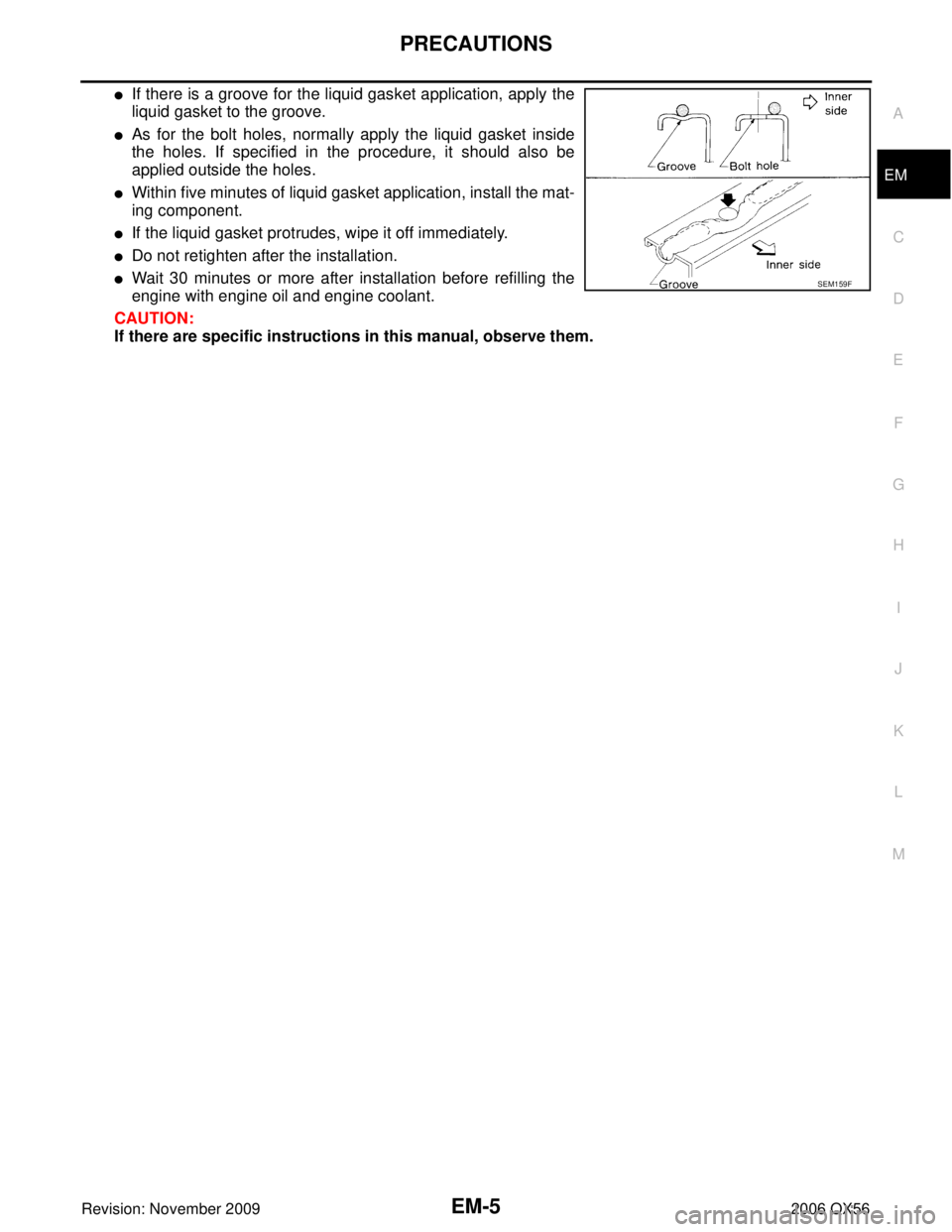
�If there is a groove for the liquid gasket application, apply the
liquid gasket to the groove.
�As for the bolt holes, normally apply the liquid gasket inside
the holes. If specified in the procedure, it should also be
applied outside the holes.
�Within five minutes of liquid gasket application, install the mat-
ing component.
�If the liquid gasket protrudes, wipe it off immediately.
�Do not retighten after the installation.
�Wait 30 minutes or more after installation before refilling the
engine with engine oil and engine coolant.
CAUTION:
If there are specific instructions in this manual, observe them.SEM159F
Page 1901 of 3383
EM-10Revision: November 2009
NOISE, VIBRATION, AND HARSHNESS (NVH) TROUBLESHOOTING
2006 QX56
NOISE, VIBRATION, AND HARSHNESS (NVH) TROUBLESHOOTINGPFP:00003
NVH Troubleshooting —Engine NoiseEBS00RES
KBIA2503E
Page 1902 of 3383
 TROUBLESHOOTINGEM-11
C
DE
F
G H
I
J
K L
M A
EM
Revision: November 2009 2006 QX56
Use the Chart Below to Help You Find the Cause of the Symptom.EBS00RET
1. Locate")
NOISE, VIBRATION, AND HARSHNESS (NVH) TROUBLESHOOTINGEM-11
C
DE
F
G H
I
J
K L
M A
EM
Revision: November 2009 2006 QX56
Use the Chart Below to Help You Find the Cause of the Symptom.EBS00RET
1. Locate the area where noise occurs.
2. Confirm the type of noise.
3. Specify the operating condition of engine.
4. Check specified noise source.
If necessary, repair or replace these parts.
A: Closely related B: Related C: Sometimes related—: Not related
Location of
noise Type of
noise Operating condition of engine
Source of noise Check item Refer-
ence page
Before
warm- up After
warm- up When
start- ing When
idling When
racing While
driv- ing
Top of
engine
Rocker
cover
Cylinder
head Ticking or
clicking
CA
—AB —Tappet noise Valve clearance EM-69
Rattle C A—ABC Camshaft
bearing noiseCamshaft journal clear-
ance
Camshaft runout EM-50EM-50
Crankshaft
pulley
Cylinder
block (Side
of engine)
Oil panSlap or
knock
—
A— BB —Piston pin
noise Piston and piston pin
clearance
Connecting rod bush-
ing clearance EM-95
EM-97
Slap or
rap
A
—— BBA Piston slap
noisePiston-to-bore clear-
ance
Piston ring side clear-
ance
Piston ring end gap
Connecting rod bend
and torsion EM-99EM-95
EM-95
EM-96
Knock A B C B B B
Connecting
rod bearing
noiseConnecting rod bush-
ing oil clearance (Small
end)
Connecting rod bear-
ing clearance (Big end)
EM-97EM-96
Knock A B
—ABC Main bearing
noiseMain bearing oil clear-
ance
Crankshaft runout EM-101EM-100
Front of
engine
Chain case
cover
Front coverTapping
or ticking
AA
—BBB Timing chain
and chain
tensioner
noiseTiming chain cracks
and wear
Timing chain tensioner
operation
EM-40
EM-37
Front of
engineSqueak-
ing or
fizzing
AB
—B— CDrive belts
(Sticking or
slipping) Drive belts deflection
EM-13
Creaking A B A B A B Drive belts
(Slipping)Idler pulley bearing
operation
Squall
Creaking AB
—BAB Water pump
noiseWater pump operation CO-19,
"INSPEC-
TION
AFTER
REMOVA
L"
Page 1903 of 3383
EM-12Revision: November 2009
ENGINE ROOM COVER
2006 QX56
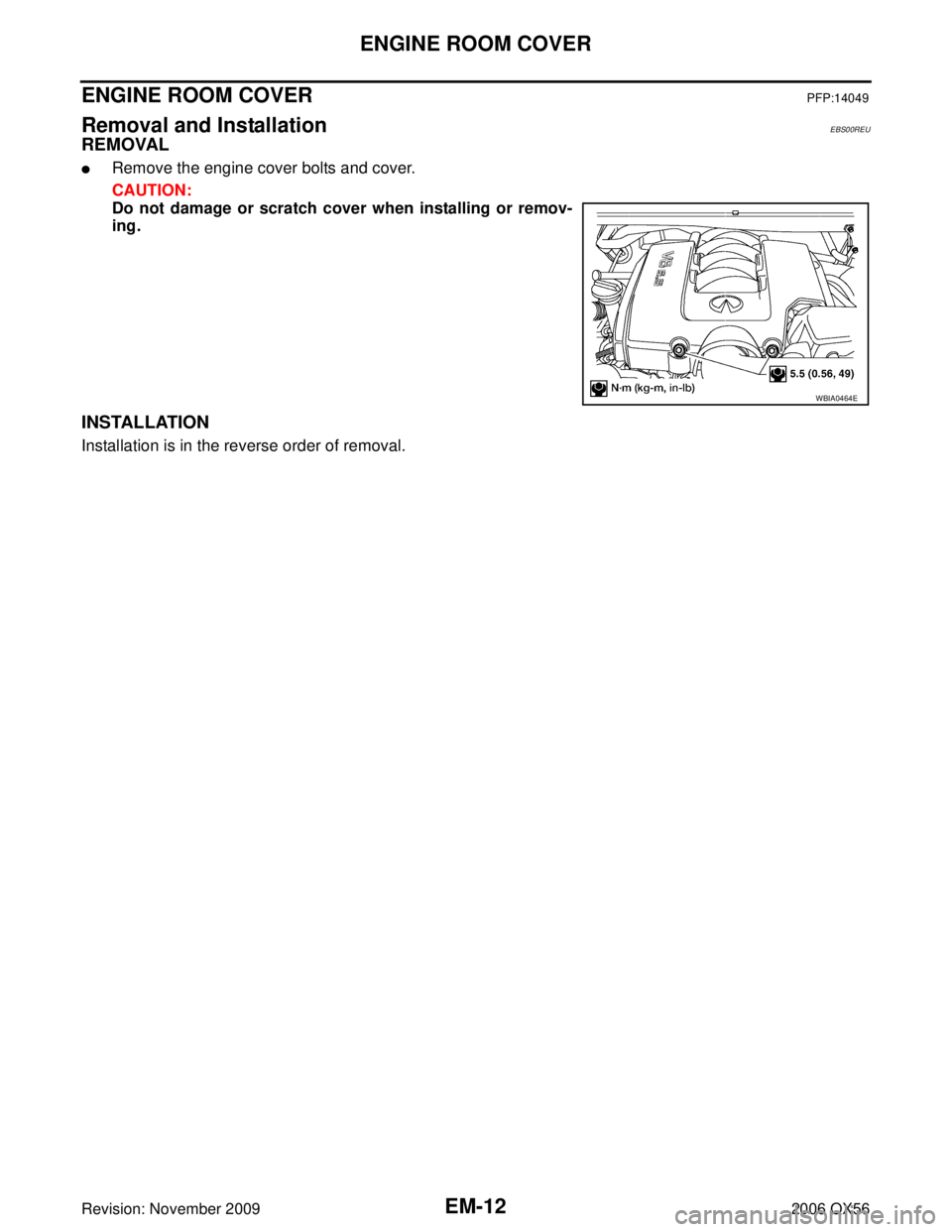
ENGINE ROOM COVERPFP:14049
Removal and InstallationEBS00REU
REMOVAL
�Remove the engine cover bolts and cover.
CAUTION:
Do not damage or scratch cover when installing or remov-
ing.
INSTALLATION
Installation is in the reverse order of removal.
WBIA0464E
Page 1904 of 3383

DRIVE BELTSEM-13
C
DE
F
G H
I
J
K L
M A
EM
Revision: November 2009 2006 QX56
DRIVE BELTSPFP:02117
Checking Drive BeltsEBS00REV
WARNING:
Be sure to perform when the engine is stopped.
1. Remove air duct and resonator assembly when inspecting drive belt.
2. Make sure that indicator (single line notch) of each auto tensioner is within the allowable working range
“A” (between three line notches) as shown.
NOTE:
�Check the drive belt auto tensioner indication when the engine is cold.
�The indicator notch is located on the moving side of the drive belt auto tensioner.
3. Visually check entire belt for wear, damage or cracks.
4. If the indicator is out of allowable working range or belt is damaged, replace the belt. Refer to EM-13,
"DRIVE BELTS" .
DRIVE BELT TENSION
There is no manual drive belt tension adjustment. The drive belt tension is automatically adjusted by the drive
belt auto tensioner.
Removal and InstallationEBS00REW
REMOVAL
1. Remove the air duct and resonator assembly. Refer to EM-15, "REMOVAL" .
2. Install Tool on drive belt auto tensioner pulley bolt, move in the direction of arrow (loosening direction of tensioner) as shown.
CAUTION:
Avoid placing hand in a location where pinching may occur
if the holding tool accidentally comes off.
3. Remove the drive belt.
1. Drive belt 2. Power steering pump pulley 3. Generator pulley
4. Crankshaft pulley 5. A/C compressor6. Idler pulley
7. Cooling fan pulley 8. Water pump pulley9. Drive belt auto tensioner
LBIA0391E
Tool number : — (J-46535)
WBIA0537E
Page 1906 of 3383
AIR CLEANER AND AIR DUCTEM-15
C
DE
F
G H
I
J
K L
M A
EM
Revision: November 2009 2006 QX56
AIR CLEANER AND AIR DUCTPFP:16500
Removal and InstallationEBS00REY
REMOVAL
1. Remove the engine room cover using power tool. Refer to EM-12, "REMOVAL" .
2. Disconnect the harness connector from air cleaner case (upper).
3. Remove the air duct and resonator assembly and air cleaner case.
4. Remove air cleaner filter and air cleaner case (lower)
�Add marks as necessary for easier installation.
INSTALLATION
Installation is in the reverse order of removal.
1. Air cleaner case (upper) 2. Air cleaner filter 3. Air cleaner case (lower)
4. Air duct and resonator assembly
WBIA0465E
 TROUBLESHOOTING
2006 QX56
NOISE, VIBRATION, AND HARSHNESS (NVH) TROUBLESHOOTINGPFP:00003
NVH Troubleshooting —Engine NoiseEBS00RES")