Page 1934 of 3383
TIMING CHAINEM-43
C
DE
F
G H
I
J
K L
M A
EM
Revision: November 2009 2006 QX56
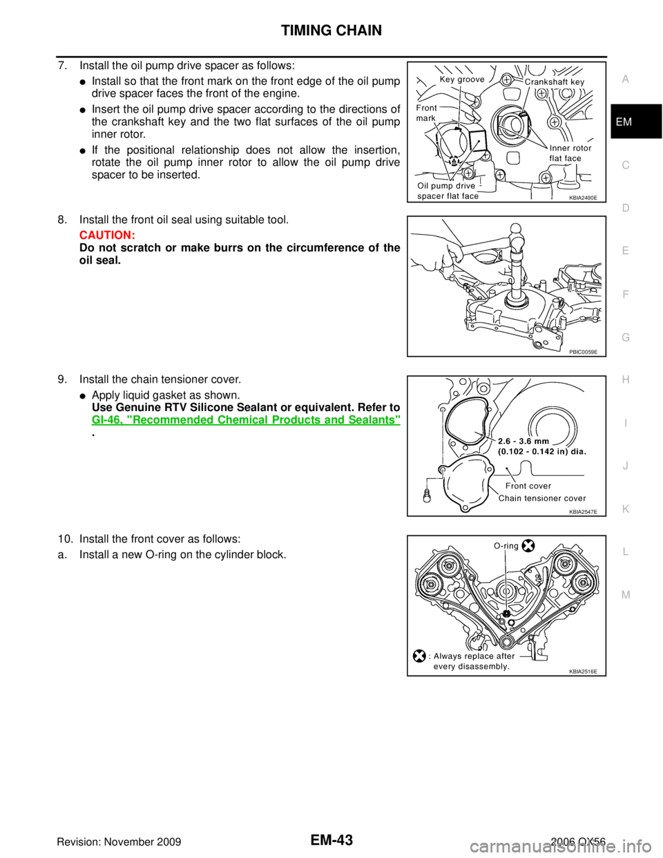
7. Install the oil pump drive spacer as follows:
�Install so that the front mark on the front edge of the oil pump
drive spacer faces the front of the engine.
�Insert the oil pump drive spacer according to the directions of
the crankshaft key and the two flat surfaces of the oil pump
inner rotor.
�If the positional relationship does not allow the insertion,
rotate the oil pump inner rotor to allow the oil pump drive
spacer to be inserted.
8. Install the front oil seal using suitable tool. CAUTION:
Do not scratch or make burrs on the circumference of the
oil seal.
9. Install the chain tensioner cover.
�Apply liquid gasket as shown.
Use Genuine RTV Silicone Sealant or equivalent. Refer to
GI-46, "
Recommended Chemical Products and Sealants"
.
10. Install the front cover as follows:
a. Install a new O-ring on the cylinder block.
KBIA2490E
PBIC0059E
KBIA2547E
KBIA2516E
Page 1936 of 3383
TIMING CHAINEM-45
C
DE
F
G H
I
J
K L
M A
EM
Revision: November 2009 2006 QX56
a. Apply engine oil onto the threaded parts of the bolt and seating area.
b. Select the one most visible notch of the four on the bolt flange.
Corresponding to the selected notch, put a alignment mark
(such as paint) on the crankshaft pulley.
14. Rotate the crankshaft pulley in normal direction (clockwise when viewed from engine front) to check for parts interference.
15. Installation of the remaining components is in the reverse of order of removal.Crankshaft pulley bolt torque
Step 1 : 93.1 N·m (9.5 kg-m, 69 ft-lb)
Step 2 : additional 90
° (angle tightening)
KBIA2519E
Page 1940 of 3383
CAMSHAFTEM-49
C
DE
F
G H
I
J
K L
M A
EM
Revision: November 2009 2006 QX56
8. Loosen camshaft sprocket bolts as shown and remove camshaft
sprockets.
CAUTION:
To avoid interference between valves and pistons, do not
turn crankshaft or camshaft with timing chain discon-
nected.
9. Remove the RH front cover bolts (A) and LH front cover bolts (B).
10. Remove RH (A) camshaft bracket bolts and LH (C) camshaft bracket bolts in the reverse of order shown to remove camshaft
brackets.
�Remove No. 1 camshaft bracket.
NOTE:
The bottom and front surface of bracket will be stuck because
of liquid gasket.
�⇐: Engine front
�B: Exhaust
�D: Intake
11. Remove the camshaft.
12. Remove the valve lifters if necessary.
�Correctly identify location where each part is removed from.
Keep parts organized to avoid mixing them up.
KBIA2485E
WBIA0706E
WBIA0707E
Page 1946 of 3383

CAMSHAFTEM-55
C
DE
F
G H
I
J
K L
M A
EM
Revision: November 2009 2006 QX56
5. Install the camshaft sprockets using the following procedure:
�A: LH bank shown
a. Install the camshaft sprockets aligning them with the matching marks painted (B) on the timing chain (C) when removed. Align
the camshaft sprocket key groove with the dowel pin on the
camshaft front edge at the same time. Then temporarily tighten
camshaft sprocket bolts.
�Install the intake and exhaust side camshaft sprockets by
selectively using the groove of the dowel pin according to the
bank. (Common part used for both banks.)
�A: Intake (I)
�B: Exhaust (E)
�R: for RH bank
�L: for LH bank
b. Lock the hexagonal part of the camshaft in the same way as for removal, and tighten the camshaft sprocket bolts.
c. Check again that the timing alignment mark on the timing chain and on each sprocket are aligned.
6. Install the chain tensioner using the following procedure: NOTE:
LH is shown.
a. Install the chain tensioner.
�Compress the plunger and hold it using a stopper pin when
installing.
�Loosen the slack guide side timing chain by rotating the cam-
shaft hexagonal part if mounting space is small.
b. Remove the stopper pin and release the plunger, and then apply tension to the timing chain.
c. Install the RH bank timing chain tensioner cover onto the front cover.
�Apply liquid gasket as shown.
Use Genuine RTV Silicone Sealant or equivalent. Refer to
GI-46, "
Recommended Chemical Products and Sealants"
.
7. Check and adjust valve clearances. Refer to EM-55, "
Va l v e
Clearance" .
8. Installation of the remaining components is in the reverse order of removal.
Va l v e C l e a r a n c eEBS00RF9
INSPECTION
NOTE:
Perform the following inspection after removal, installation or replacement of camshaft or valve-related parts,
or if there are unusual engine conditions due to changes in valve clearance over time (starting, idling, and/or
noise).
WBIA0712E
WBIA0700E
Chain tensioner bolts : 6.9 N·m (0.70 kg-m, 61 in-lb)
Tensioner cover bolts : 9.0 N·m (0.92 kg-m, 80 in-lb)KBIA2479E
KBIA2547E
Page 1947 of 3383

EM-56Revision: November 2009
CAMSHAFT
2006 QX56
1. Warm up the engine. Then stop the engine.
2. Remove the engine cover and. Refer to EM-12, "
Removal and Installation" .
3. Remove the battery cover. Refer to SC-9, "
Removal and Installation" .
4. Remove the air cleaner and air duct assembly EM-15, "
Removal and Installation" .
5. Remove the RH bank and LH bank rocker covers using power tool. Refer to EM-35, "
REMOVAL" .
6. Turn the crankshaft pulley in the normal direction (clockwise when viewed from engine front) to align TDC identification notch
(without paint mark) with timing indicator.
7. At this time, make sure both the intake and exhaust cam noses of No. 1 cylinder (top front on LH bank) face outside.
�If they do not face outside, turn crankshaft pulley once more.
8. Measure valve clearances at the locations marked “×” as shown
in the table below (locations indicated with black arrow).
�⇐ : Engine front
�⇐ (black): Measurable at No.1 cylinder compression top dead
center
�⇐ (white): Measurable at No. 3 cylinder compression top
dead center
�A: RH
�B: LH
�C: Exhaust
�D: Intake
NOTE:
Firing order 1-8-7-3-6-5-4-2
�No. 1 cylinder compression TDC
KBIA2476E
KBIA0400J
Measuring position (RH bank) No. 2 cyl
(E) No. 4 cyl
(F) No. 6 cyl
(G) No. 8 cyl
(H)
No. 1 cylinder at TDC EXH
×
INT ××
Measuring position (LH bank) No. 1 cyl
(J) No. 3 cyl
(K) No. 5 cyl
(L) No. 7 cyl
(M)
No. 1 cylinder at TDC INT
××
EXH ××
WBIA0713E
Page 1948 of 3383

CAMSHAFTEM-57
C
DE
F
G H
I
J
K L
M A
EM
Revision: November 2009 2006 QX56
�Measure valve clearance using suitable tool.Refer to EM-105,
"Valve Clearance" .
CAUTION:
If the inspection was carried out with a cold engine, make
sure the values with a fully warmed up engine are still
within specifications.
9. Turn the crankshaft pulley clockwise 270 ° from the position of No. 1 cylinder compression TDC to obtain
No. 3 cylinder compression TDC.
10. Measure valve clearances at the locations marked “×” as shown
in the table below (locations indicated with white arrow).
�⇐ : Engine front
�⇐ (black): Measurable at No.1 cylinder compression top dead
center
�⇐ (white): Measurable at No. 3 cylinder compression top
dead center
�A: RH
�B: LH
�C: Exhaust
�D: Intake
NOTE:
Firing order 1-8-7-2-3-6-5-4-2
�No. 3 cylinder compression TDC
�Measure valve clearance using suitable tool.Refer to EM-105,
"Valve Clearance" .
CAUTION:
If the inspection was carried out with a cold engine, make
sure the values with a fully warmed up engine are still
within specifications.
KBIA0185E
Measuring position (RH bank) No. 2 cyl
(E) No. 4 cyl
(F) No. 6 cyl
(G) No. 8 cyl
(H)
No. 3 cylinder at TDC EXH
×
INT ×
Measuring position (LH bank) No. 1 cyl
(J) No. 3 cyl
(K) No. 5 cyl
(L) No. 7 cyl
(M)
No. 3 cylinder at TDC INT
××
EXH ××
WBIA0713E
KBIA0185E
Page 1949 of 3383

EM-58Revision: November 2009
CAMSHAFT
2006 QX56
11. Turn the crankshaft pulley clockwise 90° from the position of No.
3 cylinder compression TDC (clockwise by 360 ° from the posi-
tion of No. 1 cylinder compression TDC) to measure the intake
and exhaust valve clearances of No. 6 cylinder and the exhaust
valve clearance of No. 2 cylinder.
12. If out of specifications, adjust as necessary. Refer to EM-58, "
ADJUSTMENT" .
ADJUSTMENT
NOTE:
�Perform adjustment depending on the selected head thickness of the valve lifter.
�The specified valve lifter thickness is the dimension at normal temperatures. Ignore dimensional differ-
ences caused by temperature. Use the specifications for hot engine condition to adjust.
1. Remove the camshaft. Refer to EM-46, "
REMOVAL" .
2. Remove the valve lifters at the locations that are out of specification.
3. Measure the center thickness of the removed valve lifters using suitable tool.
4. Use the equation below to calculate the valve lifter thickness for replacement.
�Valve lifter thickness calculation:
Thickness of replacement valve lifter = t1+ (C1 - C2)
t1 = Thickness of removed valve lifter
C1 = Measured valve clearance
C2= Standard valve clearance:
�Thickness of a new valve lifter can be identified by stamp
marks on the reverse side (inside the cylinder).
Stamp mark N788 indicates 7.88 mm (0.3102 in) in thickness.
�Available thickness of valve lifter: 25 sizes with range 7.88 to
8.36 mm (0.3102 to 0.3291 in) in steps of 0.02 mm (0.0008 in)
(when manufactured at factory). Refer to EM-106, "
Available
Valve Lifter" .
WBIA0713E
KBIA0057E
KBIA0119E
Page 1950 of 3383
CAMSHAFTEM-59
C
DE
F
G H
I
J
K L
M A
EM
Revision: November 2009 2006 QX56
5. Install the selected valve lifter.
6. Install the camshaft.
7. Manually turn the crankshaft pulley a few turns.
8. Make sure the valve clearances for a cold engine are within specifications by referring to the specified val-
ues.
9. After completing the repair, check the valve clearances again with the specifications for a warmed engine. Make sure the values are within specifications. Refer to EM-105, "
Valve Clearance" .