Page 2060 of 3383
FUEL SYSTEMFL-5
C
DE
F
G H
I
J
K L
M A
FL
Revision: November 2009 2006 QX56
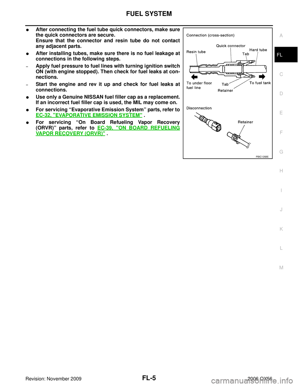
�After connecting the fuel tube quick connectors, make sure
the quick connectors are secure.
Ensure that the connector and resin tube do not contact
any adjacent parts.
�After installing tubes, make sure there is no fuel leakage at
connections in the following steps.
–Apply fuel pressure to fuel lines with turning ignition switch
ON (with engine stopped). Then check for fuel leaks at con-
nections.
–Start the engine and rev it up and check for fuel leaks at
connections.
�Use only a Genuine NISSAN fuel filler cap as a replacement.
If an incorrect fuel filler cap is used, the MIL may come on.
�For servicing “Evaporative Emission System” parts, refer to
EC-32, "
EVAPORATIVE EMISSION SYSTEM" .
�For servicing “On Board Refueling Vapor Recovery
(ORVR)” parts, refer to EC-39, "
ON BOARD REFUELING
VAPOR RECOVERY (ORVR)" .
PBIC1268E
Page 2064 of 3383

FUEL LEVEL SENSOR UNIT, FUEL FILTER AND FUEL PUMP ASSEMBLYFL-9
C
DE
F
G H
I
J
K L
M A
FL
Revision: November 2009 2006 QX56
12. Remove the lock ring using Tool.
13. Remove the fuel level sensor, fuel filter, and fuel pump assem-
bly. Remove and discard the fuel level sensor, fuel filter, and fuel
pump assembly O-ring.
CAUTION:
�Do not bend the float arm during removal.
�Avoid impacts such as dropping when handling the com-
ponents.
INSTALLATION
Installation is in the reverse order of removal.
�For installation, use a new fuel level sensor, fuel filter, and fuel pump assembly O-ring.
�Connect the quick connector as follows:
–Check the connection for any damage or foreign materials.
–Align the connector with the pipe, then insert the connector straight into the pipe until a click is heard.
–After connecting the quick connector, make sure that the con-
nection is secure by checking as follows:
–Pull the tube and the connector to make sure they are securely
connected.
–Visually inspect the connector to make sure the two retainer tabs
are securely connected.
INSPECTION AFTER INSTALLATION
1. Turn the ignition switch ON but do not start engine, then check the fuel pipes and hose connections forleaks while applying fuel pressure to the system.
2. Start the engine and rev it above idle speed, then check that there are no fuel leaks at any of the fuel pipe and hose connections.Tool number : — (J-46536)
LBIA0389E
PBIC1653E
Page 2069 of 3383

FL-14Revision: November 2009
FUEL TANK
2006 QX56
22. If necessary, remove the lock ring using Tool.
23. If necessary, remove the fuel level sensor, fuel filter, and fuelpump assembly. Discard the fuel level sensor, fuel filter, and fuel
pump assembly O-ring.
CAUTION:
�Do not bend the float arm during removal.
�Avoid impacts such as dropping when handling the com-
ponents.
INSTALLATION
Installation is in the reverse order of removal.
�For installation, use a new fuel level sensor, fuel filter, and fuel pump assembly O-ring.
�Connect the quick connector as follows:
–Check the connection for any damage or foreign materials.
–Align the connector with the pipe, then insert the connector straight into the pipe until a click is heard.
–After connecting the quick connector, make sure that the con-
nection is secure by checking as follows:
–Pull the tube and the connector to make sure they are securely
connected.
–Visually inspect the connector to make sure the two retainer tabs
are securely connected.
INSPECTION AFTER INSTALLATION
1. Turn the ignition switch ON but do not start engine, then check the fuel pipe and hose connections forleaks while applying fuel pressure.
2. Start the engine and rev it above idle, then check that there are no fuel leaks at any of the fuel pipe and hose connections.Tool number : — (J-46536)
LBIA0389E
PBIC1653E
Page 2073 of 3383
FSU-2
PRECAUTIONS
Revision: November 20092006 QX56
PRECAUTIONSPFP:00001
PrecautionsEES00253
�When installing the rubber bushings, the final tightening must be done under unladen condition and with
the tires on level ground. Oil will shorten the life of the rubber bushings, so wipe off any spilled oil immedi-
ately.
�Unladen condition means the fuel tank, engine coolant and lubricants are at the full specification. The
spare tire, jack, hand tools, and mats are in their designated positions.
�After installing suspension components, check the wheel alignment.
�Lock nuts are not reusable. Always use new lock nuts for installation. New lock nuts are pre-oiled, do not
apply any additional lubrication.
Page 2079 of 3383
.
2. Push the vehicle straight ahead about 5 m (16 ft).
3.")
FSU-8
ON-VEHICLE SERVICE
Revision: November 20092006 QX56
1. Bounce the front of vehicle up and down to stabilize the vehicle height (posture).
2. Push the vehicle straight ahead about 5 m (16 ft).
3. Put a mark on base line of the tread (rear side) of both front tires
at the same height as hub center as shown. These marks are
measuring points.
4. Measure the distance “A” on the rear side of the front tires as shown.
5. Push the vehicle slowly ahead to rotate the wheels 180 °
degrees (1/2 a turn).
CAUTION:
If the wheels have rotated more than 180 ° degrees (1/2
turn), start this procedure again from the beginning. Never
push the vehicle backward.
6. Measure the distance “B” on the front side of the front tires at the same marks as shown. Total toe-in is calculated as “A” – “B”.
7. Adjust the toe-in by varying the length of the steering outer socket.
a. Loosen the outer tie-rod lock nuts.
b. Adjust the toe-in by screwing the outer tie-rods in or out.
c. Tighten the outer tie-rod lock nuts to specification.
FRONT WHEEL TURNING ANGLE
NOTE:
Check front wheel turning angle after the toe-in inspection.
1. Place front wheels on turning radius gauges in straight ahead position and rear wheels on stands so that vehicle can be level.
Check the maximum inner and outer wheel turning angles for LH
and RH road wheels.
2. Start engine and run at idle, turn steering wheel all the way right and left, measure the turning angle.
�Any turning angles are not adjustable. If any of steering
angles are out of the specification, check if the following parts
are worn or damaged.
–Steering gear
–Steering column
–Front suspension components
AFA050
Total toe-in : Refer to FSU-19, "Wheel Alignment
(Unladen*1 )*6" .
SFA234AC
Standard length “L” : Refer to PS-26, "Steering Outer
Socket and Inner Socket" .
Lock nut : Refer to PS-15, "
Removal and
Installation" .SGIA0167E
Wheel turning angle
(full turn) : Refer to
FSU-19, "Wheel
Alignment (Unladen*1 )*6" .
SFA439BA
Page 2083 of 3383
FSU-12
STABILIZER BAR
Revision: November 20092006 QX56
STABILIZER BARPFP:54611
Removal and InstallationEES0025C
REMOVAL
1. Remove engine under cover using power tool.
2. Remove stabilizer bar mounting bracket bolts and connecting
rod nuts using power tool, as shown.
3. Remove bushings from stabilizer bar.
INSPECTION AFTER REMOVAL
�Check stabilizer bar for twist and deformation. Replace if necessary.
�Check rubber bushing for cracks, wear and deterioration. Replace if necessary.
INSTALLATION
Installation is in the reverse order of removal.
�Tighten all nuts and bolts to specification. Refer to FSU-5, "Components" .
LEIA0094E
Page 2090 of 3383
FSU-19
C
DF
G H
I
J
K L
M A
B
FSU
Revision: November 2009 2006 QX56
SERVICE DATA AND SPECIFICATIONS (SDS)PFP:00030
General SpecificationsEES0025J
Spring Free Heigh")
SERVICE DATA AND SPECIFICATIONS (SDS)FSU-19
C
DF
G H
I
J
K L
M A
B
FSU
Revision: November 2009 2006 QX56
SERVICE DATA AND SPECIFICATIONS (SDS)PFP:00030
General SpecificationsEES0025J
Spring Free HeightEES0025K
Wheel Alignment (Unladen*1 )*6EES0025L
*1: Fuel, radiator coolant and engine oil full. Spare tire, jack, hand tools and mats in designated positions.
*2: Target value 37° 31′ (37.52°)
*3: Target value 33 ° 59′ (33.98°)
*4: Target value 37 ° 44′ (37.73°)
*5: Target value 33 ° 29′ (33.48°)
*6: Some vehicles may be equipped with straight (non-adjustable) lover link bolts and washers. In order to adjust camber and ca ster on
these vehicles, first replace the lower link bolts and washers with adjustable (cam) bolts and washers. Suspension type
Independent double wishbone coil over shock
Shock absorber type Double-acting hydraulic
Stabilizer Standard equipment
2WD325.5 ± 3 mm (12.8 ± 0.1 in)
4WD 335.0 ± 3 mm (13.2 ± 0.1 in)
Drive type 2WD 4WD
Camber
Degree minute (decimal degree) Minimum -0
° 51′ (-0.85° )- 0° 33′ (-0.55 °)
Nominal -0° 6 ′ (-0.10 °)0 ° 12′ (0.20 °)
Maximum 0° 39 ′ (0.65 °)0 ° 57′ (0.95 °)
Cross camber 0° 45′ (0.75 °) or less 0 ° 45′ (0.75 °) or less
Caster
Degree minute (decimal degree) Minimum
3° 15 ′ (3.25 °)2 °45′ (2.75 °)
Nominal 4° 0 ′ (4.00 °)3 ° 30′ (3.50 °)
Maximum 4° 45 ′ (4.75 °)4 ° 15′ (4.25 °)
Cross caster 0° 45′ (0.75°) or less 0 ° 45′ (0.75 °) or less
Kingpin inclination
Degree minute (decimal degree) 13
° 32 ′ (13.53 °)1 3°13′ (13.22 °)
Total toe-in Distance (A
− B) Minimum
1.8 mm (0.07 in) 1.8 mm (0.07 in)
Nominal 2.8 mm (0.11 in) 2.8 mm (0.11 in)
Maximum 3.8 mm (0.15 in) 3.8 mm (0.15 in)
Angle (left side and right side)
Degree minute (decimal degree) Minimum
0° 3 ′ (0.05 °)0 ° 3′ (0.05 °)
Nominal 0° 5 ′ (0.08 °)0 ° 5′ (0.08 °)
Maximum 0° 7 ′ (0.12 °)0 ° 7′ (0.12 °)
Wheel turning angle
(full turn) Inside
Degree minute (decimal degree)
34
° 31′ – 38 ° 31′ *2
(34.52 ° – 38.52 °) 34°
44′ – 38 ° 44′ *4
(34.73 ° – 38.73 °)
Outside
Degree minute (decimal degree) 30
° 59′ – 34 ° 59′ *3
(30.98 ° – 34.98 °) 30°
29′ – 34 ° 29′ *5
(30.48 ° – 34.48 °)
SFA234AC
Page 2091 of 3383
FSU-20
SERVICE DATA AND SPECIFICATIONS (SDS)
Revision: November 20092006 QX56
Ball JointEES0025M
*1 Measure at cotter pin hole
*2 Measure at groove
Wheelarch Height (Unladen*1 )EES0025N
Unit: mm (in)
*1: Fuel, radiator coolant and engine oil full. Spare tire, jack, hand tools and mats in designated positions.
*2: Verify the vehicle height. If vehicle height is not within ± 10 mm (0.39 in) of the specification, perform the control unit initialization pro-
cedure. Refer to RSU-47, "
Initialization Procedure" .
Swinging force “A”
Upper ball joint 8.1 – 103.2 N (0.8 – 10.5 kg-f, 1.8 – 23.2 lb-f) *1
Lower ball joint 11.4 – 145.5 N (1.1 – 14.8 kg-f, 2.5 – 32.7 lb-f) *2
Turning torque “B” 0.5 - 6.4 N·m (0.05 - 0.65 kg-m, 4 - 57 in-lb)
Vertical end play “C” 0 mm (0 in)
SFA858AWEIA0076E
Suspension type
Air leveling*2
Applied model2WD4WD
Front wheelarch height (Hf) 913
(35.94) 931
(36.65)
Rear wheelarch height (Hr) 912
(35.91) 932
(36.69)
LEIA0085E


Revision: November 20092006 QX56
Ball JointEES0025M
*1 Measure at cotter pin hole
*2 Measure at groove
Wheelarch Height (Unladen*1 )EES0025N
Unit: mm (in)")