Page 2711 of 3383
PG-70
HARNESS CONNECTOR
Revision: November 20092006 QX56
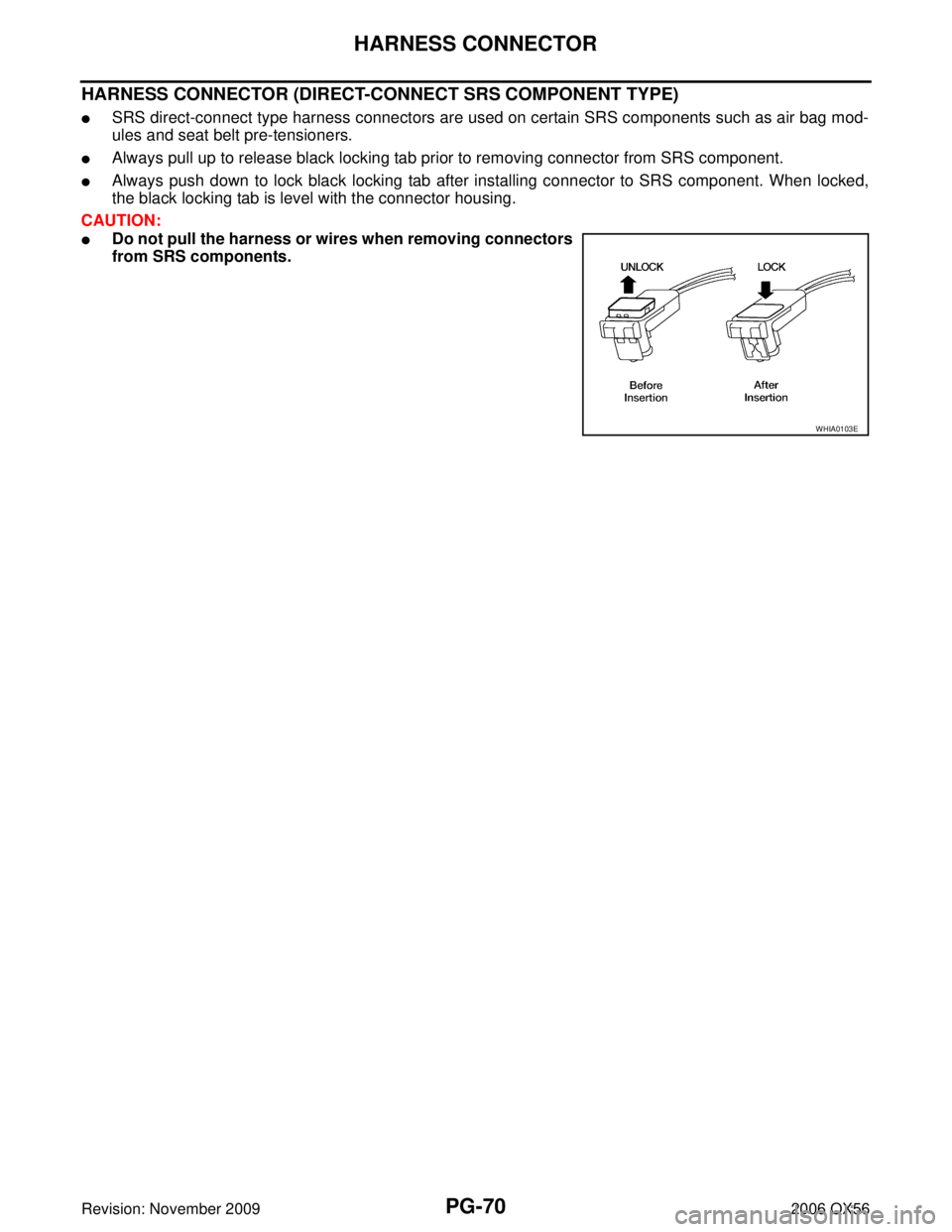
HARNESS CONNECTOR (DIRECT-CONNECT SRS COMPONENT TYPE)
�SRS direct-connect type harness connectors are used on certain SRS components such as air bag mod-
ules and seat belt pre-tensioners.
�Always pull up to release black locking tab prior to removing connector from SRS component.
�Always push down to lock black locking tab after installing connector to SRS component. When locked,
the black locking tab is level with the connector housing.
CAUTION:
�Do not pull the harness or wires when removing connectors
from SRS components.
WHIA0103E
Page 2717 of 3383
PG-76
FUSE BLOCK-JUNCTION BOX (J/B)
Revision: November 20092006 QX56
FUSE BLOCK-JUNCTION BOX (J/B)PFP:24350
Terminal ArrangementEKS00BNN
WKIA4690E
Page 2738 of 3383
 TROUBLESHOOTINGPS-5
C
DE
F
H I
J
K L
M A
B
PS
Revision: November 2009 2006 QX56
NOISE, VIBRATION, AND HARSHNESS (NVH) TROUBLESHOOTINGPFP:00003
NVH Troubleshooting")
NOISE, VIBRATION, AND HARSHNESS (NVH) TROUBLESHOOTINGPS-5
C
DE
F
H I
J
K L
M A
B
PS
Revision: November 2009 2006 QX56
NOISE, VIBRATION, AND HARSHNESS (NVH) TROUBLESHOOTINGPFP:00003
NVH Troubleshooting ChartEGS000U8
Use chart below to help you find the cause of the symptom. If necessary, repair or replace these parts.
×: ApplicableReference page
PS-6PS-6PS-18PS-18PS-18PS-6PS-7PS-7
EM-13, "
Checking Drive Belts
"
PS-7PS-13PS-15PS-11PS-10PS-15
PR-3, "
NVH Troubleshooting Chart
"
FFD-6, "
NVH Troubleshooting Chart
"
FAX-4, "
NVH Troubleshooting Chart
"
FSU-4, "
NVH Troubleshooting Chart
"
WT-4, "
NVH Troubleshooting Chart
"
WT-4, "
NVH Troubleshooting Chart
"
FAX-4, "
NVH Troubleshooting Chart
"
BR-5, "
NVH Troubleshooting Chart
"
Possible cause and sus-
pected parts
Fluid level
Air in hydraulic system
Outer socket ball joint swinging force
Outer socket ball joint rotating torque
Outer socket ball joint end play
Steering fluid leakage
Steering wheel play
Steering gear rack sliding force
Drive belt looseness
Improper steering wheel
Improper installation or looseness of tilt lock lever
Mounting rubber deterioration
Steering column deformation or damage
Improper installation or looseness of steering column
Steering linkage looseness
PROPELLER SHAFT
FRONT FINAL DRIVE
WHEEL HUB
SUSPENSION
TIRES
ROAD WHEEL
DRIVE SHAFT
BRAKES
Symptom Noise
× × ××××× × × ××××××× ×
Shake ×××× ××××× ×
Vibration ××××× × ××× ×
Shimmy ××× × ×××× ×
Shudder × × ×××× ×
Page 2739 of 3383

PS-6
POWER STEERING FLUID
Revision: November 20092006 QX56
POWER STEERING FLUIDPFP:KLF20
Checking Fluid LevelEGS000U9
Check power steering fluid level with engine off, referring to the scale
on reservoir tank.
Use HOT range for fluid temperatures of 50° – 80 °C (122 ° – 176° F).
Use COLD range for fluid temperatures of 0 ° – 30° C (32 ° – 86 °F).
CAUTION:
�Do not overfill.
�Do not reuse any used power steering fluid.
�Recommended fluid is Genuine NISSAN PSF or equivalent.
Refer to MA-11, "
RECOMMENDED FLUIDS AND LUBRI-
CANTS" .
Checking Fluid LeakageEGS000UA
Check the hydraulic piping lines for improper attachment and for
leaks, cracks, damage, loose connections, chafing or deterioration.
1. Run engine until fluid temperature reaches 50 ° – 80 °C (122 ° –
176° F) in reservoir tank. Keep engine speed idle.
2. Turn steering wheel right-to-left several times.
3. Hold steering wheel at each “lock” position for five seconds to
check fluid leakage.
CAUTION:
Do not hold steering wheel in a locked position for more
than 10 seconds. (There is the possibility that oil pump may
be damaged.)
4. If fluid leakage at connections is noticed, then loosen flare nut and then retighten. Do not over tighten con- nector as this can damage O-ring, washer and connector.
5. If fluid leakage from oil pump is noticed, check oil pump. Refer to PS-21, "
POWER STEERING OIL
PUMP" .
6. Check steering gear boots for accumulation of fluid indicating a leak from the steering gear.
Air Bleeding Hydraulic SystemEGS000UB
Incomplete air bleeding causes the following. When this happens, bleed air again.
�Air bubbles in reservoir tank.
�Clicking noise in oil pump.
�Excessive buzzing in oil pump.
NOTE:
When vehicle is stationary or while steering wheel is being turned slowly, some noise may be heard from
oil pump or gear. This noise is normal and does not affect any system.
1. Stop engine, and then turn steering wheel fully to right and left several times. CAUTION:
Do not allow steering fluid reservoir tank to go below the MIN level line. Check tank frequently and
add fluid as needed.
2. Run engine at idle speed. Turn steering wheel fully right and then fully left, hold for about three seconds. Then check for fluid leakage.
3. Repeat step 2 several times at about three second intervals. CAUTION:
Do not hold steering wheel in the locked position for more than 10 seconds. (There is the possibil-
ity that oil pump may be damaged.)
4. Check for air bubbles or cloudy fluid.
5. If air bubbles or cloudiness still exists, stop engine, perform steps 2 and 3 again until air bubbles or cloud- iness does not exist.
6. Stop engine, check fluid level.
LGIA0021E
SGIA0506E
Page 2740 of 3383

STEERING WHEELPS-7
C
DE
F
H I
J
K L
M A
B
PS
Revision: November 2009 2006 QX56
STEERING WHEELPFP:48430
On-Vehicle Inspection and ServiceEGS000UC
CHECKING CONDITION OF INSTALLATION
�Check installation condition of steering gear assembly, front suspension, axle and steering column.
�Check if movement exists when steering wheel is moved up and down, to the left and right and to the axial
direction.
�Check if the mounting nuts for steering gear assembly are loose.
Refer to PS-15, "
POWER STEERING GEAR AND LINKAGE" .
CHECKING STEERING WHEEL PLAY
1. Turn tires straight ahead, start engine, then turn steering wheel to the left and right lightly, and measure
steering wheel movement on the outer circumference when steering wheel is turned up to the point where
tires start moving.
CHECKING NEUTRAL POSITION ON STEERING WHEEL
�Check neutral position on steering wheel after confirming that front wheel alignment is correct. Refer to
FSU-6, "
Front Wheel Alignment" .
1. Turn tires straight ahead, check if steering wheel is in the neutral position.
2. If it is not in the neutral position, remove steering wheel and reinstall it correctly.
3. If the neutral position cannot be attained by repositioning the steering wheel two teeth or less on steering stem, loosen tie-rod lock nuts of steering outer sockets, then adjust tie-rods by the same amount in the
opposite direction.
CHECKING STEERING WHEEL TURNING FORCE
1. Park vehicle on a level, dry surface and set parking brake.
2. Start engine.
3. Bring power steering fluid up to operating temperature of 60 ° – 80° C (140 ° – 176° F).
4. Tires need to be inflated to specified pressure. Refer to WT-38, "
Tire" .
5. Check steering wheel turning force using Tool when steering wheel has been turned 360 ° from the neutral position.
6. If steering wheel turning force is out of specification, inspect the following:
�Steering column. Refer to PS-11, "INSPECTION AFTER
REMOVAL" .
�Power steering oil pump. Refer to PS-21, "CHECKING
RELIEF OIL PRESSURE" .
7. If steering column and power steering oil pump meet specifications, replace steering gear. Refer to PS-15,
"Removal and Installation" .
End play of the axial direction for steering wheel : 0 mm (0 in)
LGIA0024E
Steering wheel play on the outer circumference : 0
− 35 mm (0 − 1.38 in)
Tool number : J-44372
Steering wheel
turning force : 39 N (4 kg-f, 9 lb-f) or less
WGIA0035E
Page 2741 of 3383

PS-8
STEERING WHEEL
Revision: November 20092006 QX56
CHECKING FRONT WHEEL TURNING ANGLE
When checking front wheel turning angle, refer to FSU-8, "FRONT WHEEL TURNING ANGLE" .
Removal and InstallationEGS000UD
REMOVAL
1. Set the front wheels in the straight-ahead position.
2. Remove the driver air bag module. Refer to SRS-46, "
Removal and Installation" .
3. Disconnect steering wheel switches.
4. Remove the steering wheel center nut.
5. Remove the steering wheel using Tools.
CAUTION:
Place a piece of tape across the spiral cable so it will not be
rotated out of position.
6. Inspect the steering wheel near the puller holes for damage. If damaged, replace the steering wheel.
�Remove steering wheel rear cover and steering wheel
switches, if required.
INSTALLATION
Installation is in the reverse order of removal.
�Align spiral cable correctly when installing steering wheel. Make
sure that the spiral cable is in the neutral position. The neutral
position is detected by turning left 2.6 revolutions from the right
end position and ending with the knob at the top.
�If equipped with VDC, refer to BRC-62, "Adjustment of Steering
Angle Sensor Neutral Position" for steering angle sensor adjust-
ment.
�After the work is completed, perform self-diagnosis to make sure
no malfunction is detected. Refer to SRS-20, "
SRS Operation
Check" .
�Tighten steering wheel center nut to specification. Refer to PS-10, "Removal and Installation" .
CAUTION:
�The spiral cable may snap due to steering operation if the
cable is not installed in the correct position.
�With the steering linkage disconnected, the cable may snap
by turning the steering wheel beyond the limited number of
turns. The spiral cable can be turned counterclockwise
about 2.5 turns from the neutral position. Tool number A: KV481J0010 (J-1859-A)
B: KV481J0020 (J-42578)
WHIA0124E
WGIA0038E
PHIA0275E
Page 2744 of 3383

STEERING COLUMNPS-11
C
DE
F
H I
J
K L
M A
B
PS
Revision: November 2009 2006 QX56
4. Remove lock nut and bolt, then separate upper shaft from upper
joint.
5. Remove two nuts and two bolts, then remove steering column assembly from steering member.
6. Remove hole cover seal and clamp.
7. Remove mounting nuts, then remove hole cover from dash panel.
8. Raise vehicle, then remove mounting bolt (lower side) of lower joint shaft and remove lower joint shaft and upper shaft as an
assembly.
INSPECTION AFTER REMOVAL
�Check for damage to steering column jacket tube. If damage is found, replace steering column with new
one.
�If vehicle has been in a collision, check column length “L1” and
“L2 ” as shown. If out of specification, replace steering column
with new one.
�Check for proper lubrication, apply grease as necessary.
INSTALLATION
Installation is in the reverse order of removal.
LGIA0027E
LGIA0028E
LGIA0029E
Steering column length
L1 : 158 mm (6.22 in)
L2 : 262 mm (10.31 in)
SGIA0475E
Page 2745 of 3383

PS-12
STEERING COLUMN
Revision: November 20092006 QX56
CAUTION:
�When installing the steering column, finger-tighten all of the lower bracket and joint retaining
bolts; then tighten them to specification. Do not apply undue stress to the steering column.
�The lower nut on the upper joint may not be reused.
NOTE:
Align slit of the coupling joint with projection on dust cover. Insert the
joint until surface "A" contacts surface "B".
�After installation, turn steering wheel to make sure it moves
smoothly. Make sure the number of turns are the same from the
straight-forward position to left and right locks. Make sure that
the steering wheel is in a neutral position when driving straight
ahead.
�When installing steering column to steering member, install
mounting nut from front side of vehicle.
INSPECTION AFTER INSTALLATION
�After installing steering column to vehicle, check tilt device operation range is within specification.
�Check if steering wheel operation can turn to the end of the left
and right stops smoothly.
SST491C
Range "A" : 61.3 mm (2.41 in)
WGIA0083E

Revision: November 20092006 QX56
FUSE BLOCK-JUNCTION BOX (J/B)PFP:24350
Terminal ArrangementEKS00BNN
WKIA4690E")