Page 2896 of 3383

SEAT BELTSSB-7
C
DE
F
G
I
J
K L
M A
B
SB
Revision: November 2009 2006 QX56
REMOVAL
1. Remove seat belt lower anchor cover and bolt.
2. Remove the D-ring anchor bolt cover and D-ring anchor bolt.
3. Remove the upper and lower luggage area trim. Refer to EI-35, "
BODY SIDE TRIM" .
4. Remove the seat belt guide bolt.
5. Remove seat belt retractor anchor bolt and the seat belt assembly.
6. Remove the seat belt height adjuster assembly.
INSTALLATION
Installation is in the reverse order of removal.
�Ensure that seat belt height adjuster is locked in the lowest position during installation.
SECOND ROW SEAT BELT BUCKLE
Removal
1. Remove the rear bucket seat.
2. Remove the screw and seat cushion inner finisher. Refer to SE-
98, "Second Row Center"
3. Remove the anchor bolt and buckle.
4. Remove the rear bench seat. Refer to SE-98, "
Second Row Outboard" .
5. Remove the seat cushion finisher.
6. Remove the anchor bolt and buckle.
Installation
Installation is in the reverse order of removal.
SECOND ROW SEAT BELT RETRACTOR - BENCH SEAT
Removal
1. Remove seat belt anchor.
2. Remove seat belt bezel.
3. Remove seat back upholstery and foam. Refer to SE-99, "
Disassembly and Assembly" .
4. Remove seat belt retractor cover.
5. Remove bolt and remove seat belt retractor and seat belt assembly.
Installation
Installation is in the reverse order of removal.
WHIA0347E
Page 2898 of 3383
SEAT BELTSSB-9
C
DE
F
G
I
J
K L
M A
B
SB
Revision: November 2009 2006 QX56
INSTALLATION
Installation is in the reverse order of removal.
�Make sure seat belt height adjuster is locked in the lowest position during installation.
�Seat belt anchor base should be flat to the floor during installation and not on the anti-rotation bead.
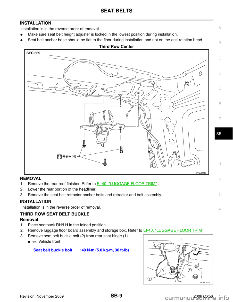
Third Row Center
REMOVAL
1. Remove the rear roof finisher. Refer to EI-40, "LUGGAGE FLOOR TRIM" .
2. Lower the rear portion of the headliner.
3. Remove the seat belt retractor anchor bolts and retractor and belt assembly.
INSTALLATION
Installation is in the reverse order of removal.
THIRD ROW SEAT BELT BUCKLE
Removal
1. Place seatback RH/LH in the folded position.
2. Remove luggage floor board assembly and storage box. Refer to EI-40, "
LUGGAGE FLOOR TRIM" .
3. Remove seat belt buckle bolt (2) from rear seat hinge (1).
�⇐ : Vehicle front
WHIA0284E
Seat belt buckle bolt : 49 N·m (5.0 kg-m, 36 ft-lb)
LHIA0107E
Page 2899 of 3383
SB-10
SEAT BELTS
Revision: November 20092006 QX56
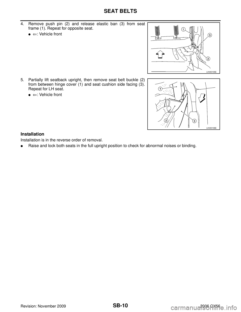
4. Remove push pin (2) and release elastic ban (3) from seat
frame (1). Repeat for opposite seat.
�⇐: Vehicle front
5. Partially lift seatback upright, then remove seat belt buckle (2) from between hinge cover (1) and seat cushion side facing (3).
Repeat for LH seat.
�⇐: Vehicle front
Installation
Installation is in the reverse order of removal.
�Raise and lock both seats in the full upright position to check for abnormal noises or binding.
LHIA0105E
LHIA0106E
Page 2901 of 3383
 and Automatic Locking Retractors (ALR)
NOTE:
All seat belt retractors are of t")
SB-12
SEAT BELTS
Revision: November 20092006 QX56
SEAT BELT RETRACTOR ON-VEHICLE CHECK
Emergency Locking Retractors (ELR) and Automatic Locking Retractors (ALR)
NOTE:
All seat belt retractors are of the Emergency Locking Retractors (ELR) type. In an emergency (sudden stop)
the retractor will lock and prevent the belt from extending any further. All 3-point type seat belt retractors
except the driver's seat belt also have an Automatic Locking Retractors (ALR) mode. The ALR mode (also
called child restraint mode) is used when installing child seats. The ALR mode is activated when the seat belt
is fully extended. When the belt is then retracted partially, the ALR mode automatically locks the seat belt in a
specific position so the belt cannot be extended any further. To cancel the ALR mode, allow the seat belt to
fully wind back into the retractor.
Check the seat belt retractors using the following test(s) to determine if a seat belt retractor and belt assembly
is operating properly.
ELR Function Stationary Check
Grasp the shoulder belt and pull forward quickly. The retractor should lock and prevent the belt from extending
further.
ALR Function Stationary Check
1. Pull out entire length of seat belt from retractor until a click is heard.
2. Retract the belt partially. A clicking noise should be heard as the belt retracts indicating that the retractor is
in the Automatic Locking Retractor (ALR) mode.
3. Grasp the seat belt and try to pull out the retractor. The belt must lock and not extend any further. If neces- sary replace the seat belt retractor and belt assembly.
4. Allow the entire length of the belt to retract to cancel the automatic locking mode.
ELR Function Moving Check
WARNING:
Perform the following test in a safe, open area clear of other vehicles and obstructions (for example, a
large, empty parking lot). Road surface must be paved and dry. DO NOT perform the following test on
wet or gravel roads or on public streets and highways. This could result in an accident and serious
personal injury. The driver and passenger must be prepared to brace themselves in the event the
retractor does not lock.
1. Fasten drivers seat belt. Buckle a passenger into the seat for the belt that is to be tested.
2. Proceed to the designated safe area.
3. Drive the vehicle at approximately 16 km/h (10 MPH). Notify any passengers of a pending sudden stop. The driver and passenger must be prepared to brace themselves in the event the retractor does not lock.
Apply brakes firmly and make a very hard stop.
During stop, seat belts should lock and not be extended. If the seat belt retractor and belt assembly does not
lock, perform the retractor off-vehicle check.
SEAT BELT RETRACTOR OFF-VEHICLE CHECK
1. Remove the seat belt retractor and belt assembly.
2. Slowly pull out belt while tilting the retractor assembly forward from the mounted position without twisting the retractor assembly as shown in the illustration.
Page 2902 of 3383
SEAT BELTSSB-13
C
DE
F
G
I
J
K L
M A
B
SB
Revision: November 2009 2006 QX56
If NG, replace the retractor assembly.15 degrees or less tilt : Belt can be pulled out.
35 degrees or more tilt : Belt locks and cannot be pulled out.
PHIA0257E
Page 2915 of 3383

SC-10
STARTING SYSTEM
Revision: November 20092006 QX56
STARTING SYSTEMPFP:23300
System DescriptionEKS00B7B
Power is supplied at all times:
�through 40A fusible link (letter m , located in the fuse and fusible link box)
�to ignition switch terminal B.
With the ignition switch in the START position, power is supplied:
�from ignition switch terminal ST
�to IPDM E/R terminal 21.
With the ignition switch in the ON or START position, power is supplied to IPDM E/R (intelligent power distribu-
tion module engine room) CPU.
With the selector lever in the P or N position, power is supplied:
�through A/T assembly terminal 9
�to IPDM E/R terminal 48.
Ground is supplied at all times:
�to IPDM E/R terminals 38 and 59
�through body grounds E9, E15 and E24.
Then the starter relay is turned on.
The IPDM E/R is energized and power is supplied:
�from terminal 19 of the IPDM E/R
�to terminal 1 of the starter motor windings.
The starter motor plunger closes and provides a closed circuit between the battery and the starter motor. The
starter motor is grounded to the cylinder block. With power and ground supplied, the starter motor operates.
Page 2922 of 3383

CHARGING SYSTEMSC-17
C
DE
F
G H
I
J
L
M A
B
SC
Revision: November 2009 2006 QX56
CHARGING SYSTEMPFP:23100
System DescriptionEKS00B7H
The generator provides DC voltage to operate the vehicle's electrical system and to keep the battery charged.
The voltage output is controlled by the IC regulator.
Power is supplied at all times:
�to generator terminal 4
�through 10A fuse (No. 30, located in the fuse and fusible link box).
Terminal 1 supplies power to charge the battery and operate the vehicle's electrical system. Output voltage is
controlled by the IC regulator at terminal 4 detecting the input voltage. The charging circuit is protected by the
140A fusible link (letter a , located in the fusible link box).
Ground is supplied:
�to generator terminal 2
�through body ground E203.
With the ignition switch in the ON or START position, power is supplied:
�through 10A fuse [No. 14, located in the fuse block (J/B)]
�to combination meter terminal 24 for the charge warning lamp.
Ground is supplied to terminal 13 of the combination meter through terminal 3 of the generator. With power
and ground supplied, the charge warning lamp will illuminate. When the generator is providing sufficient volt-
age with the engine running, the ground is opened and the charge warning lamp will go off.
If the charge warning lamp illuminates with the engine running, a fault is indicated.
Page 2927 of 3383
SC-22
CHARGING SYSTEM
Revision: November 20092006 QX56
DIAGNOSTIC PROCEDURE 1
Check Charge Warning Lamp Circuit
1. CHECK CHARGE WARNING LAMP CIRCUIT CONNECTION
1. Turn the ignition switch OFF.
2. Check to see if terminal 3 is clean and tight.
OK or NG
OK >> GO TO 2.
NG >> Repair terminal 3 connection. Confirm repair by performing complete Battery/Starting/Charging system test.
2. CHECK CHARGE WARNING LAMP CIRCUIT
1. Disconnect E205 connector from generator.
2. Apply ground to connector E205 terminal 3 with the ignition switch in the ON position.
OK or NG
OK >> GO TO SC-21, "WORK FLOW" .
NG >> Check the following.
�10A fuse [No. 14, located in fuse block (J/B)]
�Charge warning lamp
�Harness for open or short between combination
meter and fuse
�Harness for open or short between combination meter and generator
Charge warning lamp should
light up.
WKIA2110E