2006 INFINITI M35 air condition
[x] Cancel search: air conditionPage 4868 of 5621
PDU (POWER DISTRIBUTION UNIT)
PG-41
C
D
E
F
G
H
I
J
L
MA
B
PG
Revision: 2006 January2006 M35/M45
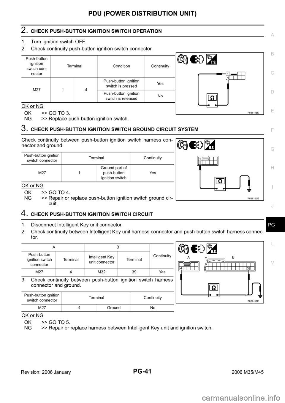
2. CHECK PUSH-BUTTON IGNITION SWITCH OPERATION
1. Turn ignition switch OFF.
2. Check continuity push-button ignition switch connector.
OK or NG
OK >> GO TO 3.
NG >> Replace push-button ignition switch.
3. CHECK PUSH-BUTTON IGNITION SWITCH GROUND CIRCUIT SYSTEM
Check continuity between push-button ignition switch harness con-
nector and ground.
OK or NG
OK >> GO TO 4.
NG >> Repair or replace push-button ignition switch ground cir-
cuit.
4. CHECK PUSH-BUTTON IGNITION SWITCH CIRCUIT
1. Disconnect Intelligent Key unit connector.
2. Check continuity between Intelligent Key unit harness connector and push-button switch harness connec-
tor.
3. Check continuity between push-button ignition switch harness
connector and ground.
OK or NG
OK >> GO TO 5.
NG >> Repair or replace harness between Intelligent Key unit and ignition switch.
Push-button
ignition
switch con-
nectorTerminal Condition Continuity
M27 1 4Push-button ignition
switch is pressedYe s
Push-button ignition
switch is releasedNo
PIIB6118E
Push-button ignition
switch connectorTerminal Continuity
M27 1Ground part of
push-button
ignition switchYe s
PIIB6120E
AB
Continuity Push-button
ignition switch
connectorTerminalIntelligent Key
unit connectorTerminal
M27 4 M32 39 Yes
Push-button ignition
switch connectorTerminal Continuity
M27 4 Ground No
PIIB6119E
Page 4869 of 5621
PG-42
PDU (POWER DISTRIBUTION UNIT)
Revision: 2006 January2006 M35/M45
Check Push-Button Ignition Switch (Indicator Circuit) SystemNKS004EN
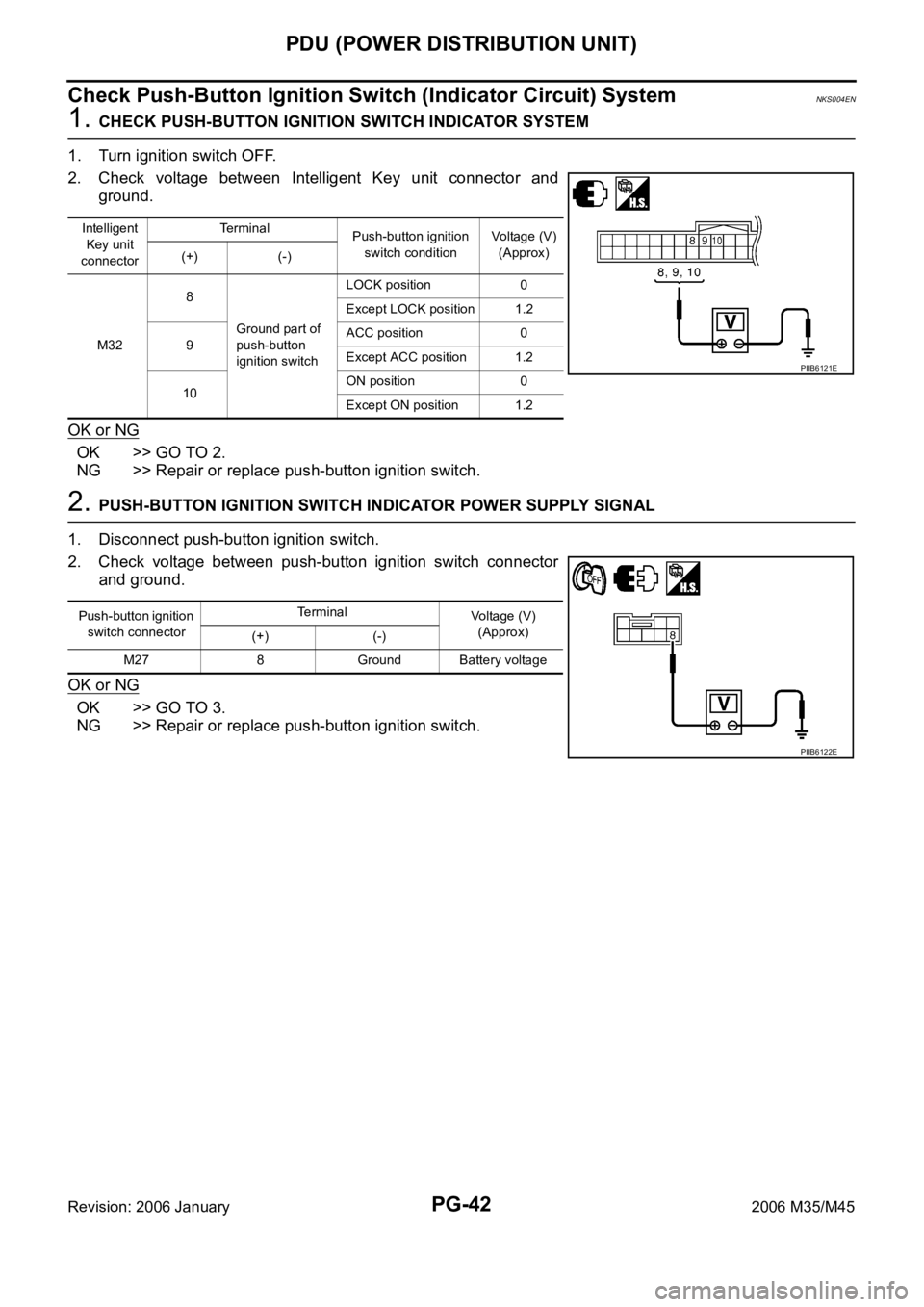
1. CHECK PUSH-BUTTON IGNITION SWITCH INDICATOR SYSTEM
1. Turn ignition switch OFF.
2. Check voltage between Intelligent Key unit connector and
ground.
OK or NG
OK >> GO TO 2.
NG >> Repair or replace push-button ignition switch.
2. PUSH-BUTTON IGNITION SWITCH INDICATOR POWER SUPPLY SIGNAL
1. Disconnect push-button ignition switch.
2. Check voltage between push-button ignition switch connector
and ground.
OK or NG
OK >> GO TO 3.
NG >> Repair or replace push-button ignition switch.
Intelligent
Key unit
connectorTe r m i n a l
Push-button ignition
switch conditionVoltage (V)
(Approx)
(+) (-)
M328
Ground part of
push-button
ignition switchLOCK position 0
Except LOCK position 1.2
9ACC position 0
Except ACC position 1.2
10ON position 0
Except ON position 1.2
PIIB6121E
Push-button ignition
switch connectorTerminal
Voltage (V)
(Approx)
(+) (-)
M27 8 Ground Battery voltage
PIIB6122E
Page 4870 of 5621
PDU (POWER DISTRIBUTION UNIT)
PG-43
C
D
E
F
G
H
I
J
L
MA
B
PG
Revision: 2006 January2006 M35/M45
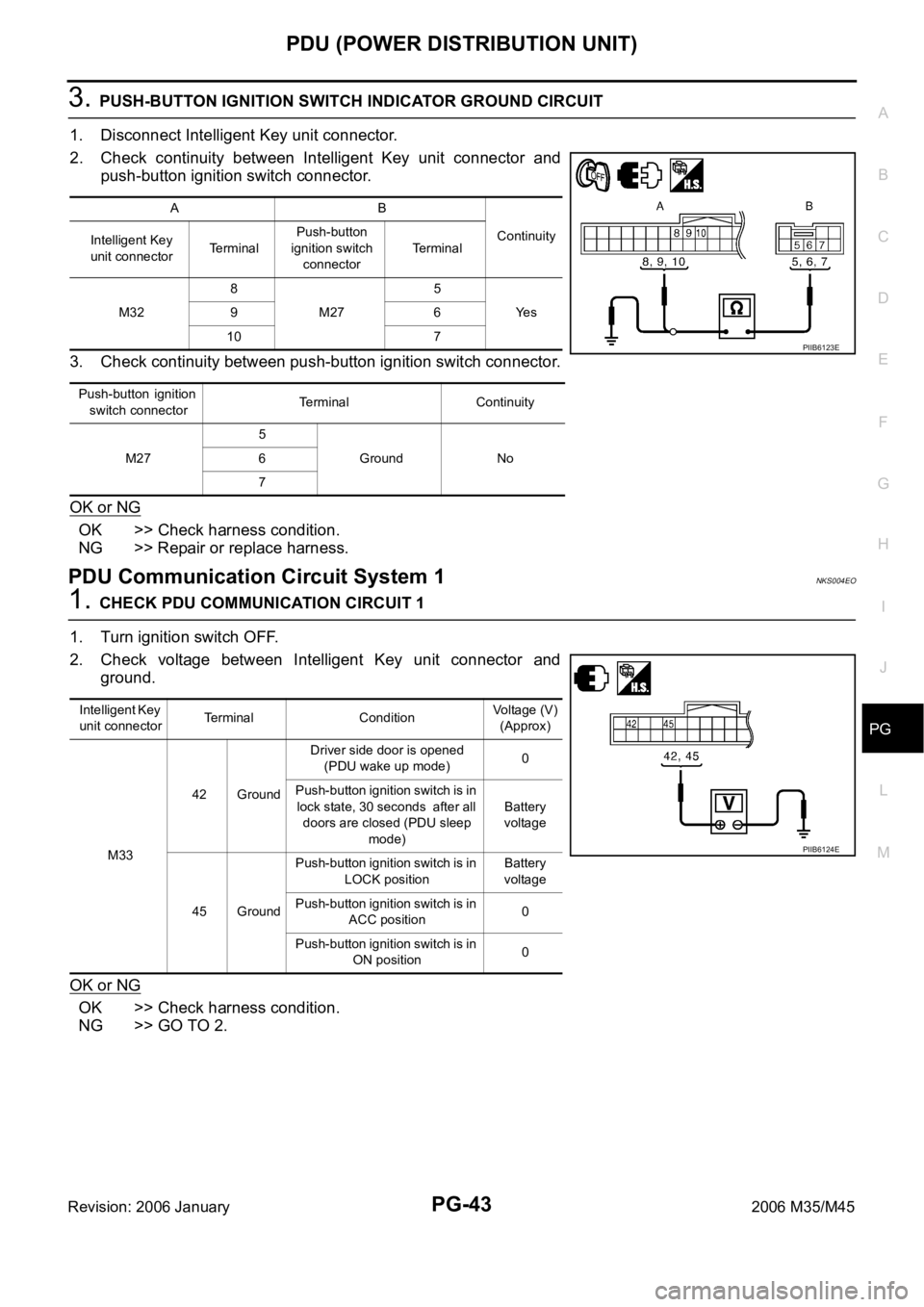
3. PUSH-BUTTON IGNITION SWITCH INDICATOR GROUND CIRCUIT
1. Disconnect Intelligent Key unit connector.
2. Check continuity between Intelligent Key unit connector and
push-button ignition switch connector.
3. Check continuity between push-button ignition switch connector.
OK or NG
OK >> Check harness condition.
NG >> Repair or replace harness.
PDU Communication Circuit System 1NKS004EO
1. CHECK PDU COMMUNICATION CIRCUIT 1
1. Turn ignition switch OFF.
2. Check voltage between Intelligent Key unit connector and
ground.
OK or NG
OK >> Check harness condition.
NG >> GO TO 2.
AB
Continuity
Intelligent Key
unit connectorTerminalPush-button
ignition switch
connectorTe r m i n a l
M328
M275
Ye s 96
10 7
P u s h - b u t t o n i g n i t i o n
switch connectorTerminal Continuity
M275
Ground No 6
7
PIIB6123E
Intelligent Key
unit connectorTerminal ConditionVoltage (V)
(Approx)
M3342 GroundDriver side door is opened
(PDU wake up mode)0
Push-button ignition switch is in
lock state, 30 seconds after all
doors are closed (PDU sleep
mode)Battery
voltage
45 GroundPush-button ignition switch is in
LOCK positionBattery
voltage
Push-button ignition switch is in
ACC position0
Push-button ignition switch is in
ON position0
PIIB6124E
Page 4871 of 5621
PG-44
PDU (POWER DISTRIBUTION UNIT)
Revision: 2006 January2006 M35/M45
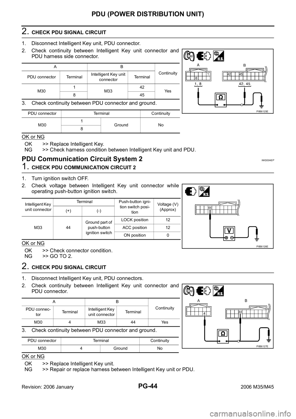
2. CHECK PDU SIGNAL CIRCUIT
1. Disconnect Intelligent Key unit, PDU connector.
2. Check continuity between Intelligent Key unit connector and
PDU harness side connector.
3. Check continuity between PDU connector and ground.
OK or NG
OK >> Replace Intelligent Key.
NG >> Check harness condition between Intelligent Key unit and PDU.
PDU Communication Circuit System 2NKS004EP
1. CHECK PDU COMMUNICATION CIRCUIT 2
1. Turn ignition switch OFF.
2. Check voltage between Intelligent Key unit connector while
operating push-button ignition switch.
OK or NG
OK >> Check connector condition.
NG >> GO TO 2.
2. CHECK PDU SIGNAL CIRCUIT
1. Disconnect Intelligent Key unit, PDU connectors.
2. Check continuity between Intelligent Key unit connector and
PDU connector.
3. Check continuity between PDU connector and ground.
OK or NG
OK >> Replace Intelligent Key unit.
NG >> Repair or replace harness between Intelligent Key unit or PDU.
AB
Continuity
PDU connector TerminalIntelligent Key unit
connectorTerminal
M301
M3342
Ye s
845
PDU connector Terminal Continuity
M301
Ground No
8
PIIB6125E
Intelligent Key
unit connectorTerminal Push-button igni-
tion switch posi-
tionVoltage (V)
(Approx)
(+) (-)
M33 44Ground part of
push-button
ignition switchLOCK position 12
ACC position 12
ON position 0
PIIB6126E
AB
Continuity
PDU connec-
torTerminalIntelligent Key
unit connectorTerminal
M30 4 M33 44 Yes
PDU connector Terminal Continuity
M30 4 Ground No
PIIB6127E
Page 4920 of 5621

HARNESS
PG-93
C
D
E
F
G
H
I
J
L
MA
B
PG
Revision: 2006 January2006 M35/M45
Wiring Diagram Codes (Cell Codes) NKS004ET
Use the chart below to find out what each wiring diagram code stands for.
Refer to the wiring diagram code in the alphabetical index to find the location (page number) of each wiring
diagram.
Code Section Wiring Diagram Name
A/C ATC Air Conditioner
AF1B1 EC Air Fuel Ratio Sensor 1 Bank 1
AF1B2 EC Air Fuel Ratio Sensor 1 Bank 2
AF1HB1 EC Air Fuel Ratio Sensor 1 Heater Bank 1
AF1HB2 EC Air Fuel Ratio Sensor 1 Heater Bank 2
AFS LT Adaptive Front Lighting System
APPS1 EC Accelerator Pedal Position Sensor
APPS2 EC Accelerator Pedal Position Sensor
APPS3 EC Accelerator Pedal Position Sensor
ASC/BS EC Automatic Speed Control Device (ASCD) Brake Switch
ASC/SW EC Automatic Speed Control Device (ASCD) Steering Switch
ASCBOF EC Automatic Speed Control Device (ASCD) Brake Switch
ASCIND EC Automatic Speed Control Device (ASCD) Indicator
AT/IND DI A/T Indicator Lamp
AUT/DP SE Automatic Drive Positioner
AUTO/L LT Automatic Light System
AV AV Audio and Visual System
AWD TF AWD Control System
BACK/L LT Back-Up Lamp
BRK/SW EC Brake Switch
C/SEAT SE Climate Controlled Seat
CAN AT CAN Communication Line
CAN EC CAN Communication Line
CAN LAN CAN System
CHARGE SC Charging System
CHIME DI Warning Chime
CIGAR WW Cigarette Lighter
CLOCK DI Clock
COMBSW LT Combination Switch
COMPAS DI Compass and Thermometer
COOL/F EC Cooling Fan Control
CUR/SE EC Battery Current Sensor
D/LOCK BL Power Door Lock
DEF GW Rear Window Defogger
DTRL LT Headlamp - with Daytime Light System
ECM/PW EC ECM Power Supply for Back-Up
ECTS EC Engine Coolant Temperature Sensor
ENG/ST BL Engine Start System
EPS STC Electric Controlled Power Steering System
ETC1 EC Electric Throttle Control Function
ETC2 EC Electric Throttle Control Motor Relay
Page 4954 of 5621

PS-1
POWER STEERING SYSTEM
G STEERING
CONTENTS
C
D
E
F
H
I
J
K
L
M
SECTION PS
A
B
PS
Revision: 2006 January2006 M35/M45
POWER STEERING SYSTEM
PRECAUTIONS .......................................................... 3
Precautions for Supplemental Restraint System
(SRS) “AIR BAG” and “SEAT BELT PRE-TEN-
SIONER” .................................................................. 3
Precautions Necessary for Steering Wheel Rotation
after Battery Disconnect ........................................... 3
OPERATION PROCEDURE ................................. 3
Precautions for Steering System .............................. 4
PREPARATION ........................................................... 5
Special Service Tools [SST] ..................................... 5
Commercial Service Tools ........................................ 6
NOISE, VIBRATION AND HARSHNESS (NVH)
TROUBLESHOOTING ................................................ 7
NVH Trouble Shooting Chart .................................... 7
POWER STEERING FLUID ........................................ 8
Checking Fluid Level ...........................................
..... 8
Checking Fluid Leakage ........................................... 8
Air Bleeding Hydraulic System ................................. 8
STEERING WHEEL .................................................. 10
On-Vehicle Inspection and Service ........................ 10
CHECKING CONDITION OF INSTALLATION .... 10
CHECKING STEERING WHEEL PLAY .............. 10
CHECKING NEUTRAL POSITION STEERING
WHEEL ............................................................... 10
CHECKING STEERING WHEEL TURNING
FORCE ................................................................ 10
CHECKING FRONT WHEEL TURNING ANGLE .... 11
Removal and Installation ........................................ 12
REMOVAL ........................................................
... 12
INSTALLATION ................................................... 12
STEERING COLUMN ............................................... 13
Removal and Installation ........................................ 13
COMPONENTS .................................................. 13
REMOVAL OF UPPER JOINT, COLLAR, HOLE
COVER SEAL, HOLE COVER, LOWER SHAFT
AND LOWER JOINT ........................................... 14
INSPECTION AFTER REMOVAL ....................... 14INSTALLATION OF UPPER JOINT, COLLAR,
HOLE COVER SEAL, HOLE COVER, LOWER
SHAFT AND LOWER JOINT .............................. 14
REMOVAL OF STEERING COLUMN ASSEM-
BLY ...................................................................... 15
INSPECTION AFTER REMOVAL ....................... 16
INSTALLATION OF STEERING COLUMN
ASSEMBLY ......................................................... 16
INSPECTION AFTER INSTALLATION ................ 16
Disassembly and Assembly .................................... 17
COMPONENTS ................................................... 17
DISASSEMBLY ................................................... 17
INSPECTION AFTER DISASSEMBLY ................ 17
ASSEMBLY ......................................................... 17
INSPECTION AFTER ASSEMBLY ...................... 17
POWER STEERING GEAR ...................................... 18
Removal and Installation ........................................ 18
COMPONENTS ................................................... 18
REMOVAL ........................................................
... 18
INSTALLATION ................................................... 19
INSPECTION AFTER INSTALLATION ................ 19
Disassembly and Assembly .................................
... 20
COMPONENTS ................................................... 20
DISASSEMBLY ................................................... 21
INSPECTION AFTER DISASSEMBLY ................ 22
ASSEMBLY ......................................................... 24
POWER STEERING OIL PUMP ............................... 29
On-Vehicle Inspection and Service ......................... 29
CHECKING RELIEF OIL PRESSURE ................ 29
Removal and Installation ........................................ 29
REMOVAL ........................................................
... 29
INSTALLATION ................................................... 29
Disassembly and Assembly (Models with VK45DE) ... 30
COMPONENTS ................................................... 30
INSPECTION BEFORE DISASSEMBLY ............. 30
DISASSEMBLY ................................................... 31
INSPECTION AFTER DISASSEMBLY ................ 31
Page 4972 of 5621
POWER STEERING GEAR
PS-19
C
D
E
F
H
I
J
K
L
MA
B
PS
Revision: 2006 January2006 M35/M45
8. Remove steering hydraulic piping bracket from front suspension member. Refer to PS-38, "HYDRAULIC
LINE" .
9. Remove EPS solenoid valve harness connector. Refer to PS-20, "
COMPONENTS" .
10. Remove rack stay (2WD) or front cross bar (AWD). Refer to FSU-8, "
Components" , FSU-25, "Compo-
nents" .
11. Remove mounting bolts and nuts of steering gear assembly, and then remove steering gear assembly
from vehicle.
INSTALLATION
Installation is the reverse order of removal. For tightening torque, refer to PS-18, "COMPONENTS" .
When installing lower joint to steering gear assembly, follow the procedure listed below.
–Set rack of steering gear in the neutral position.
NOTE:
To get the neutral position of rack, turn gear-sub assembly and measure the distance of inner socket, and
then measure the intermediate position of the distance.
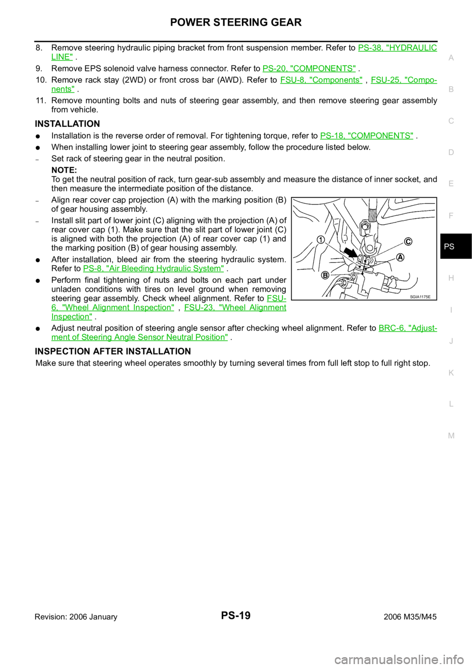
–Align rear cover cap projection (A) with the marking position (B)
of gear housing assembly.
–Install slit part of lower joint (C) aligning with the projection (A) of
rear cover cap (1). Make sure that the slit part of lower joint (C)
is aligned with both the projection (A) of rear cover cap (1) and
the marking position (B) of gear housing assembly.
After installation, bleed air from the steering hydraulic system.
Refer to PS-8, "
Air Bleeding Hydraulic System" .
Perform final tightening of nuts and bolts on each part under
unladen conditions with tires on level ground when removing
steering gear assembly. Check wheel alignment. Refer to FSU-
6, "Wheel Alignment Inspection" , FSU-23, "Wheel Alignment
Inspection" .
Adjust neutral position of steering angle sensor after checking wheel alignment. Refer to BRC-6, "Adjust-
ment of Steering Angle Sensor Neutral Position" .
INSPECTION AFTER INSTALLATION
Make sure that steering wheel operates smoothly by turning several times from full left stop to full right stop.
SGIA1175E
Page 5017 of 5621

RF-4
SQUEAK AND RATTLE TROUBLE DIAGNOSES
Revision: 2006 January2006 M35/M45
SQUEAK AND RATTLE TROUBLE DIAGNOSESPFP:00000
Work FlowNIS0023N
CUSTOMER INTERVIEW
Interview the customer if possible, to determine the conditions that exist when the noise occurs. Use the Diag-
nostic Worksheet during the interview to document the facts and conditions when the noise occurs and any
customer's comments; refer to RF-8, "
Diagnostic Worksheet" . This information is necessary to duplicate the
conditions that exist when the noise occurs.
The customer may not be able to provide a detailed description or the location of the noise. Attempt to
obtain all the facts and conditions that exist when the noise occurs (or does not occur).
If there is more than one noise in the vehicle, be sure to diagnose and repair the noise that the customer
is concerned about. This can be accomplished by test driving the vehicle with the customer.
After identifying the type of noise, isolate the noise in terms of its characteristics. The noise characteristics
are provided so the customer, service adviser and technician are all speaking the same language when
defining the noise.
Squeak —(Like tennis shoes on a clean floor)
Squeak characteristics include the light contact/fast movement/brought on by road conditions/hard sur-
faces=higher pitch noise/softer surfaces=lower pitch noises/edge to surface=chirping
Creak—(Like walking on an old wooden floor)
Creak characteristics include firm contact/slow movement/twisting with a rotational movement/pitch
dependent on materials/often brought on by activity.
Rattle—(Like shaking a baby rattle)
Rattle characteristics include the fast repeated contact/vibration or similar movement/loose parts/missing
clip or fastener/incorrect clearance.
Knock —(Like a knock on a door)
Knock characteristics include hollow sounding/sometimes repeating/often brought on by driver action.
Tick—(Like a clock second hand)
Tick characteristics include gentle contacting of light materials/loose components/can be caused by driver
action or road conditions.
Thump—(Heavy, muffled knock noise)
Thump characteristics include softer knock/dead sound often brought on by activity.
Buzz—(Like a bumble bee)
Buzz characteristics include high frequency rattle/firm contact.
Often the degree of acceptable noise level will vary depending upon the person. A noise that you may
judge as acceptable may be very irritating to the customer.
Weather conditions, especially humidity and temperature, may have a great effect on noise level.
SBT842