2006 INFINITI M35 power steering
[x] Cancel search: power steeringPage 1100 of 5621

INTELLIGENT KEY SYSTEM/ENGINE START FUNCTION
BL-161
C
D
E
F
G
H
J
K
L
MA
B
BL
Revision: 2006 January2006 M35/M45
2. CHECK POWER DISTRIBUTION UNIT POWER SUPPLY
Check voltage between power distribution unit connector and ground.
OK or NG
OK >> GO TO 3.
NG >> Check if "B2558 PDU" is displayed on self-diagnosis results. If it is displayed, first perform the
diagnosis.
3. CHECK POWER SUPPLY CIRCUIT
1. Turn ignition switch OFF.
2. Disconnect power distribution unit and steering lock unit connector.
3. Check continuity between power distribution unit connector and steering lock unit connector.
4. Check continuity between power distribution unit connector and
ground.
OK or NG
OK >> GO TO 5.
NG >> Repair or replace harness.
Terminals
ConditionVoltage (V)
(Approx.) (+)
(–)
Power distribution
unit connectorTerminal
M30 3 GroundWhen turn ignition
switch to OFF
(steering lock oper-
ates)Battery voltage
0
Battery voltage
Ignition switch OFF 0
PIIB6228E
AB
Continuity
P o w e r d i s t r i b u t i o n
unit connectorTerminal Steering lock unit
connectorTerminal
M30 3 M35 1 Yes
A
GroundContinuity
Power distribution
unit connectorTerminal
M30 3 No
PIIB6229E
Page 1101 of 5621

BL-162
INTELLIGENT KEY SYSTEM/ENGINE START FUNCTION
Revision: 2006 January2006 M35/M45
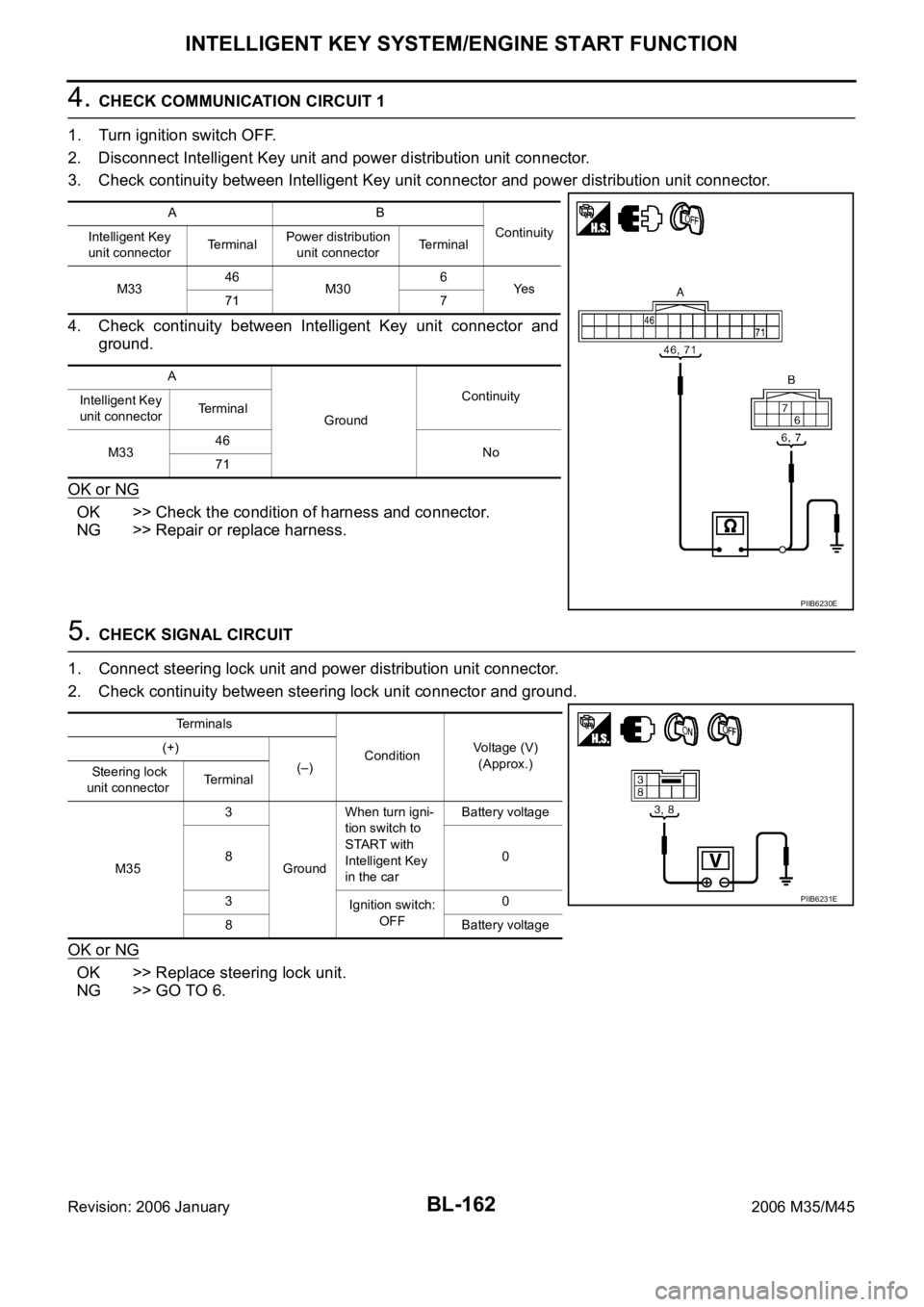
4. CHECK COMMUNICATION CIRCUIT 1
1. Turn ignition switch OFF.
2. Disconnect Intelligent Key unit and power distribution unit connector.
3. Check continuity between Intelligent Key unit connector and power distribution unit connector.
4. Check continuity between Intelligent Key unit connector and
ground.
OK or NG
OK >> Check the condition of harness and connector.
NG >> Repair or replace harness.
5. CHECK SIGNAL CIRCUIT
1. Connect steering lock unit and power distribution unit connector.
2. Check continuity between steering lock unit connector and ground.
OK or NG
OK >> Replace steering lock unit.
NG >> GO TO 6.
AB
Continuity
Intelligent Key
unit connectorTe r m i n a lPower distribution
unit connectorTerminal
M3346
M306
Ye s
71 7
A
GroundContinuity
Intelligent Key
unit connectorTerminal
M3346
No
71
PIIB6230E
Terminals
ConditionVoltage (V)
(Approx.) (+)
(–)
Steering lock
unit connectorTerminal
M353
GroundWhen turn igni-
tion switch to
START with
Intelligent Key
in the carBattery voltage
80
3
Ignition switch:
OFF0
8 Battery voltage
PIIB6231E
Page 1102 of 5621

INTELLIGENT KEY SYSTEM/ENGINE START FUNCTION
BL-163
C
D
E
F
G
H
J
K
L
MA
B
BL
Revision: 2006 January2006 M35/M45
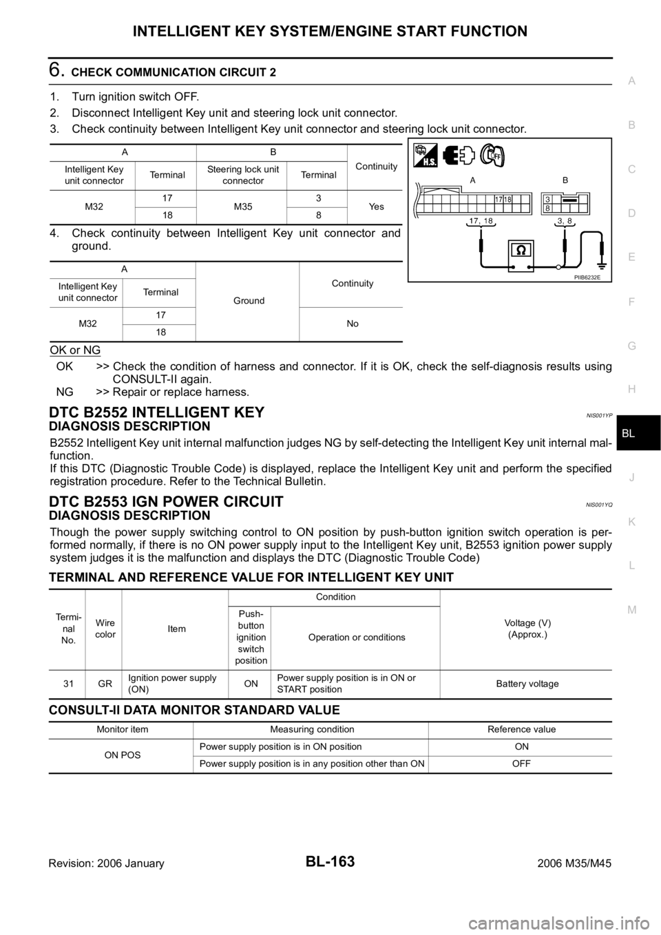
6. CHECK COMMUNICATION CIRCUIT 2
1. Turn ignition switch OFF.
2. Disconnect Intelligent Key unit and steering lock unit connector.
3. Check continuity between Intelligent Key unit connector and steering lock unit connector.
4. Check continuity between Intelligent Key unit connector and
ground.
OK or NG
OK >> Check the condition of harness and connector. If it is OK, check the self-diagnosis results using
CONSULT-II again.
NG >> Repair or replace harness.
DTC B2552 INTELLIGENT KEYNIS001YP
DIAGNOSIS DESCRIPTION
B2552 Intelligent Key unit internal malfunction judges NG by self-detecting the Intelligent Key unit internal mal-
function.
If this DTC (Diagnostic Trouble Code) is displayed, replace the Intelligent Key unit and perform the specified
registration procedure. Refer to the Technical Bulletin.
DTC B2553 IGN POWER CIRCUITNIS001YQ
DIAGNOSIS DESCRIPTION
Though the power supply switching control to ON position by push-button ignition switch operation is per-
formed normally, if there is no ON power supply input to the Intelligent Key unit, B2553 ignition power supply
system judges it is the malfunction and displays the DTC (Diagnostic Trouble Code)
TERMINAL AND REFERENCE VALUE FOR INTELLIGENT KEY UNIT
CONSULT-II DATA MONITOR STANDARD VALUE
AB
Continuity
Intelligent Key
unit connectorTerminalSteering lock unit
connectorTerminal
M3217
M353
Ye s
18 8
A
GroundContinuity
Intelligent Key
unit connectorTerminal
M3217
No
18
PIIB6232E
Te r m i -
nal
No.Wire
colorItemCondition
Voltage (V)
(Approx.) Push-
button
ignition
switch
positionOperation or conditions
31 GRIgnition power supply
(ON)ONPower supply position is in ON or
START positionBattery voltage
Monitor item Measuring condition Reference value
ON POSPower supply position is in ON position ON
Power supply position is in any position other than ON OFF
Page 1190 of 5621

IVIS (INFINITI VEHICLE IMMOBILIZER SYSTEM-NATS)
BL-251
C
D
E
F
G
H
J
K
L
MA
B
BL
Revision: 2006 January2006 M35/M45
Operation DescriptionNIS0020E
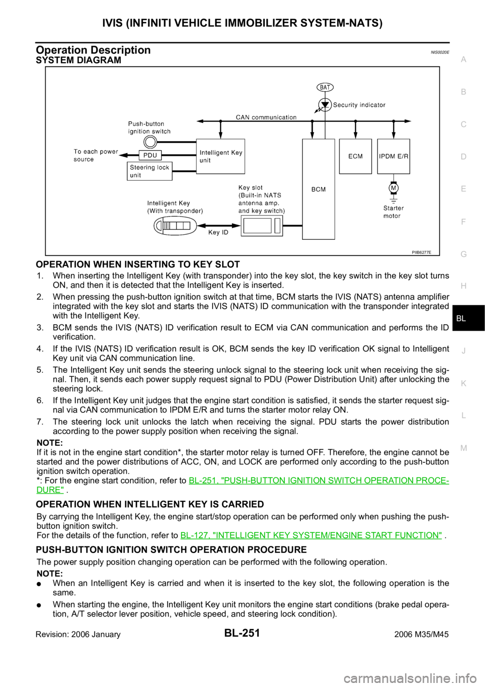
SYSTEM DIAGRAM
OPERATION WHEN INSERTING TO KEY SLOT
1. When inserting the Intelligent Key (with transponder) into the key slot, the key switch in the key slot turns
ON, and then it is detected that the Intelligent Key is inserted.
2. When pressing the push-button ignition switch at that time, BCM starts the IVIS (NATS) antenna amplifier
integrated with the key slot and starts the IVIS (NATS) ID communication with the transponder integrated
with the Intelligent Key.
3. BCM sends the IVIS (NATS) ID verification result to ECM via CAN communication and performs the ID
verification.
4. If the IVIS (NATS) ID verification result is OK, BCM sends the key ID verification OK signal to Intelligent
Key unit via CAN communication line.
5. The Intelligent Key unit sends the steering unlock signal to the steering lock unit when receiving the sig-
nal. Then, it sends each power supply request signal to PDU (Power Distribution Unit) after unlocking the
steering lock.
6. If the Intelligent Key unit judges that the engine start condition is satisfied, it sends the starter request sig-
nal via CAN communication to IPDM E/R and turns the starter motor relay ON.
7. The steering lock unit unlocks the latch when receiving the signal. PDU starts the power distribution
according to the power supply position when receiving the signal.
NOTE:
If it is not in the engine start condition*, the starter motor relay is turned OFF. Therefore, the engine cannot be
started and the power distributions of ACC, ON, and LOCK are performed only according to the push-button
ignition switch operation.
*: For the engine start condition, refer to BL-251, "
PUSH-BUTTON IGNITION SWITCH OPERATION PROCE-
DURE" .
OPERATION WHEN INTELLIGENT KEY IS CARRIED
By carrying the Intelligent Key, the engine start/stop operation can be performed only when pushing the push-
button ignition switch.
For the details of the function, refer to BL-127, "
INTELLIGENT KEY SYSTEM/ENGINE START FUNCTION" .
PUSH-BUTTON IGNITION SWITCH OPERATION PROCEDURE
The power supply position changing operation can be performed with the following operation.
NOTE:
When an Intelligent Key is carried and when it is inserted to the key slot, the following operation is the
same.
When starting the engine, the Intelligent Key unit monitors the engine start conditions (brake pedal opera-
tion, A/T selector lever position, vehicle speed, and steering lock condition).
PIIB6277E
Page 1203 of 5621

BL-264
IVIS (INFINITI VEHICLE IMMOBILIZER SYSTEM-NATS)
Revision: 2006 January2006 M35/M45
Terminals and Reference Value for Intelligent Key UnitNIS0020I
Te r m i -
nal
No.Wire
colorItemCondition
Voltage (V)
(Approx.) Push-
button
ignition
switch
positionOperation or conditions
1 SB Power source (fuse) — — Battery voltage
3YIPDM E/R current sig-
nalSTART At starter motor cranking 5
LOCK Any condition other than above 2
8WPush-button ignition
switch LOCK indicatorLOCKPower supply position is in LOCK
position0
—Power supply position is in any posi-
tion other than LOCK1.2
9LPush-button ignition
switch ACC indicatorACCPower supply position is in ACC posi-
tion0
—Power supply position is in any posi-
tion other than ACC1.2
10 VPush-button ignition
switch ON indicatorONPower supply position is in ON posi-
tion0
—Power supply position is in any posi-
tion other than ON1.2
11 P Stop lamp switch —Brake pedal depressed Battery voltage
Brake pedal released Battery voltage
12 L/RPush-button ignition
switch illumination—Push-button ignition switch illumina-
tion is turned on2.6
Push-button ignition switch illumina-
tion is turned off
(15 seconds or more after the driver
door is closed)0
13 LG/B Key slot illumination LOCKDriver door is opened under the condi-
tion that the Intelligent Key is inserted
into the key slot0
Battery voltage 0
Intelligent Key is removed from key
slot (when key slot illumination is
turned off)0
15 LGSteering lock unit
power sourceLOCK — Battery voltage
16 P/BSteering lock unit sig-
nalLOCK Steering lock: Lock Battery voltage
ACCSteering lock: Unlock
(Unlocked moment)0
17 OSteering lock unit con-
dition signal-1LOCK Steering lock: Lock 0
ACC
Steering lock: UnlockBattery voltage
ON Battery voltage
18 L/YSteering lock unit con-
dition signal-2LOCK Steering lock: Lock Battery voltage
ACC
Steering lock: Unlock0
ON 0
19 BR/Y Key switch LOCKIntelligent Key is inserted into key slot Battery voltage
Intelligent Key is removed from key
slot0
20 B Ground — — 0
Page 1204 of 5621

IVIS (INFINITI VEHICLE IMMOBILIZER SYSTEM-NATS)
BL-265
C
D
E
F
G
H
J
K
L
MA
B
BL
Revision: 2006 January2006 M35/M45
27 VA/T device (Detention
switch)LOCK A/T selector lever is in P position 0
ONA/T selector lever is in any position
other than PBattery voltage
28 SB Starter relayON A/T selector lever is in N or P position Battery voltage
—Power supply position is in LOCK
position or A/T selector lever is in any
position other than N or P position0
29 V/R Stop lamp switch —Brake pedal depressed Battery voltage
Brake pedal released 0
30 L/WIgnition power supply
(ACC)ACCPower supply position is in ACC posi-
tionBattery voltage
31 GRIgnition power supply
(ON)ONPower supply position is in ON posi-
tionBattery voltage
33 O PDU signalLOCK Steering lock: Lock 0
ACC Steering lock: Unlock 8
34 R PDU feed back signal LOCK At wake-up (Open driver door) 0
35 LG Vehicle speed signal ONAt speedometer operation (vehicle
speed approx. 40 km/h)
37 P CAN L — — —
38 L CAN H — — —
39 BR/WPush-button ignition
switch—Push-button ignition switch is pressed 0
Push-button ignition switch is released Battery voltage
40 B Ground — — 0
41 Y Power source (fuse) — — Battery voltage
42 P PDU wake up signalLOCKAt sleep (30 seconds or more after all
doors are closed under the condition
that the power supply position is in the
LOCK position)Battery voltage
— At wake-up (Open driver door) 0
43 G Starter signalON At starter motor cranking 0
— Other than above Battery voltage
46 V PDU signal— Steering lock: Lock Battery voltage
LOCK Steering lock: Unlocked moment 0
56 B Ground — — 0
57 L Power source (fuse) — — Battery voltage
58 OA/T device (Detention
switch)LOCKAt sleep (30 seconds or more after all
doors are closed under the condition
that the power supply position is in the
LOCK position)0
— At wake-up (Open driver door) Battery voltage Te r m i -
nal
No.Wire
colorItemCondition
Voltage (V)
(Approx.) Push-
button
ignition
switch
positionOperation or conditions
PKIA1935E
Page 1205 of 5621

BL-266
IVIS (INFINITI VEHICLE IMMOBILIZER SYSTEM-NATS)
Revision: 2006 January2006 M35/M45
Terminals and Reference Value for Steering Lock UnitNIS0020J
Terminals and Reference Value for BCMNIS0020K
71 LG PDU signalLOCK Steering lock: Lock Battery voltage
ACC Steering lock: Unlocked moment 0
72 B Ground — — 0 Te r m i -
nal
No.Wire
colorItemCondition
Voltage (V)
(Approx.) Push-
button
ignition
switch
positionOperation or conditions
Te r m i -
nal
No.Wire
colorItemCondition
Voltage (V)
(Approx.) Push-
button
ignition
switch
positionOperation or conditions
1 GR PDU signal LOCKPress push-button ignition switch with
Intelligent Key inside vehicle0
Battery voltage 0
(Battery voltage is detected when
pressing the push-button ignition
switch)
3 O Condition signal-1LOCK Steering lock: Lock 0
ACC
Steering lock: UnlockBattery voltage
ON Battery voltage
4 P/B Intelligent Key unit signalLOCK Steering lock: Lock Battery voltage
ACC
Steering lock: Unlock0
ON 0
5 B Ground — — 0
6 B Ground — — 0
7 LG Power source — — Battery voltage
8 L/Y Condition signal-2LOCK Steering lock: Lock Battery voltage
ACC
Steering lock: Unlock0
ON 0
Te r m i -
nal
No.Wire
colorItemCondition
Voltage (V)
(Approx.) Push-but-
ton igni-
tion
switch
positionOperation or conditions
21 GRNATS antenna amp.
(Built-in key slot)LOCKIgnition switch is pressed while
inserting the Intelligent Key into the
key slotJust after pressing ignition switch.
Pointer of tester should move
23 W/V Security indicator LOCKIntelligent Key is removed from key
slot and power supply position is in
LOCK positionBattery voltage
0
(Every 2.4 seconds)
25 W/RNATS antenna amp.
(Built-in key slot)LOCKIgnition switch is pressed while
inserting the Intelligent Key into the
key slotJust after pressing ignition switch.
Pointer of tester should move
37 LGKey slot
(Key switch signal)LOCKIntelligent Key is removed from key
slot0
Intelligent Key is inserted into key slot Battery voltage
Page 1206 of 5621

IVIS (INFINITI VEHICLE IMMOBILIZER SYSTEM-NATS)
BL-267
C
D
E
F
G
H
J
K
L
MA
B
BL
Revision: 2006 January2006 M35/M45
Terminals and Reference Value for IPDM E/RNIS0020L
Terminals and Reference Value for PDUNIS0020M
38 WIgnition power supply
(ON or START)ONPower supply position is in ON posi-
tionBattery voltage
39 L CAN H — — —
40 P CAN L — — —
42 P Power source (fuse) — — Battery voltage
52 B Ground — — 0
55 WPower source (Fusible
link)— — Battery voltage Te r m i -
nal
No.Wire
colorItemCondition
Voltage (V)
(Approx.) Push-but-
ton igni-
tion
switch
positionOperation or conditions
Te r -
minal
No.Wire
ColorItemCondition
Voltage (V)
(Approx.) Push-
button
ignition
switch
positionOperation or conditions
4W/RStarter motor power
supplyLOCK — 0
START Starter motor is activating Battery voltage
49 L CAN H — — —
50 P CAN L — — —
53 GR/RA/T Shift position
signalONA/T shift position is P/ N posi-
tionBattery voltage
LOCK Other than above 0
Te r -
minal
No.Wire
colorItemCondition
Voltage (V)
(Approx.) Push-
button
ignition
switch
positionOperation or conditions
1 P Wake up signalLOCKSleep condition (30 seconds or more
after all doors are closed under the con-
dition that the power supply position is in
the LOCK position)Battery voltage
— Wake-up condition (Open driver door) 0
2 G Starter control signalON At starter motor cranking 0
— Any condition other than above Battery voltage
3GRSteering lock unit
power sourceLOCKPush-button ignition switch is pressed
under the condition that Intelligent Key is
in the vehicle or Intelligent Key is inserted0
Battery voltage 0
— Any condition other than above 0