2006 INFINITI M35 trunk release
[x] Cancel search: trunk releasePage 993 of 5621

BL-54
INTELLIGENT KEY SYSTEM
Revision: 2006 January2006 M35/M45
Keyless Power Window Down (Open) Function
All power windows open when the unlock button on Intelligent Key is activated and kept pressed for more than
3 seconds with the ignition switch OFF. The windows keep opening if the unlock button is continuously
pressed.
The power window opening stops when the following operations are performed:
When the unlock button is kept pressed more than 15 seconds.
When the ignition switch is turned ON while the power window opening is operated.
When the unlock button is released.
While retained power operation activate, Keyless power window down (open) Function cannot be operated.
Keyless power window down operation mode can be changed by “P/W DOWN DELAY” mode in “WORK SUP-
PORT”. Refer to BL-83, "
WORK SUPPORT" .
Room Lamp Illumination Operation
When the following conditions are met:
Condition of interior lamp switch is in DOOR position
Door switch OFF (all the doors are closed)
Intelligent Key system turns on interior lamp (for 30 seconds) by receiving UNLOCK signal from Intelligent
Key. For detailed description, refer to LT- 2 7 0 , "
ROOM LAMP TIMER OPERATION" .
List of Operation Related Parts
Parts marked with are the parts related to operation.
ENGINE START FUNCTION
Refer to BL-127, "INTELLIGENT KEY SYSTEM/ENGINE START FUNCTION" .
Remote keyless entry functions
Intelligent Key
Key slot
Door request switch (Driver, Passenger)
Door switch
Trunk room lamp switch
Door lock actuator
Trunk lid opener actuator
Intelligent Key warning buzzer
Intelligent Key unit
CAN communication system
BCM
Combination meter
Hazard warning lamp
Horn
IPDM E/R
Head lamp
Door lock/unlock function by remote control button
Trunk open function by remote control button
Hazard and horn reminder function
Selective unlock function
Keyless power window down (open) function
Auto door lock function
Panic alarm function
Page 1042 of 5621
INTELLIGENT KEY SYSTEM
BL-103
C
D
E
F
G
H
J
K
L
MA
B
BL
Revision: 2006 January2006 M35/M45
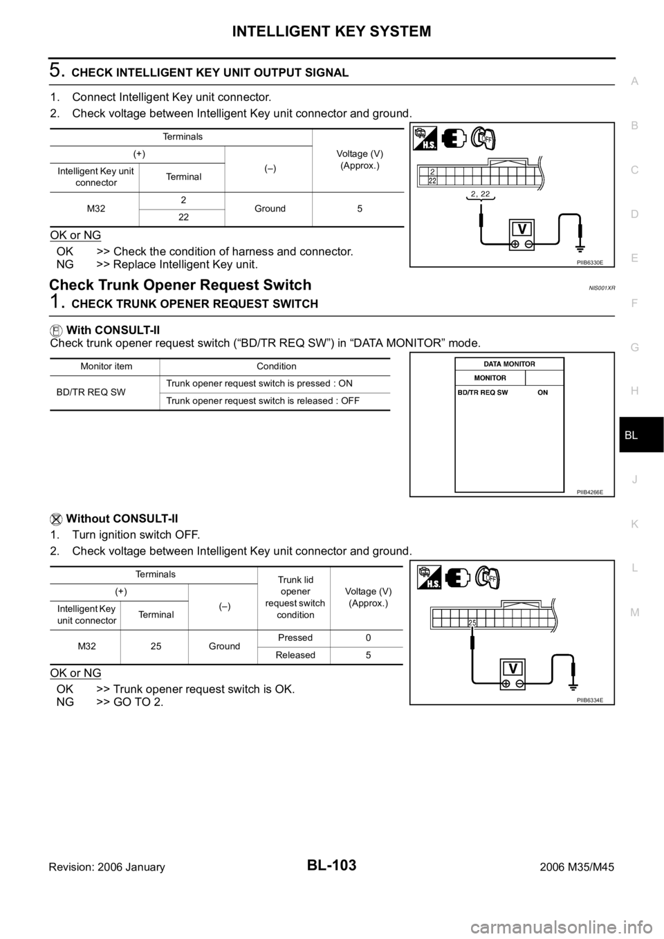
5. CHECK INTELLIGENT KEY UNIT OUTPUT SIGNAL
1. Connect Intelligent Key unit connector.
2. Check voltage between Intelligent Key unit connector and ground.
OK or NG
OK >> Check the condition of harness and connector.
NG >> Replace Intelligent Key unit.
Check Trunk Opener Request SwitchNIS001XR
1. CHECK TRUNK OPENER REQUEST SWITCH
With CONSULT-II
Check trunk opener request switch (“BD/TR REQ SW”) in “DATA MONITOR” mode.
Without CONSULT-II
1. Turn ignition switch OFF.
2. Check voltage between Intelligent Key unit connector and ground.
OK or NG
OK >> Trunk opener request switch is OK.
NG >> GO TO 2.
Terminals
Voltage (V)
(Approx.) (+)
(–)
Intelligent Key unit
connectorTerminal
M322
Ground 5
22
PIIB6330E
Monitor item Condition
BD/TR REQ SWTrunk opener request switch is pressed : ON
Trunk opener request switch is released : OFF
PIIB4266E
Terminals
Trunk lid
opener
request switch
conditionVoltage (V)
(Approx.) (+)
(–)
Intelligent Key
unit connectorTerminal
M32 25 GroundPressed 0
Released 5
PIIB6334E
Page 1043 of 5621
BL-104
INTELLIGENT KEY SYSTEM
Revision: 2006 January2006 M35/M45
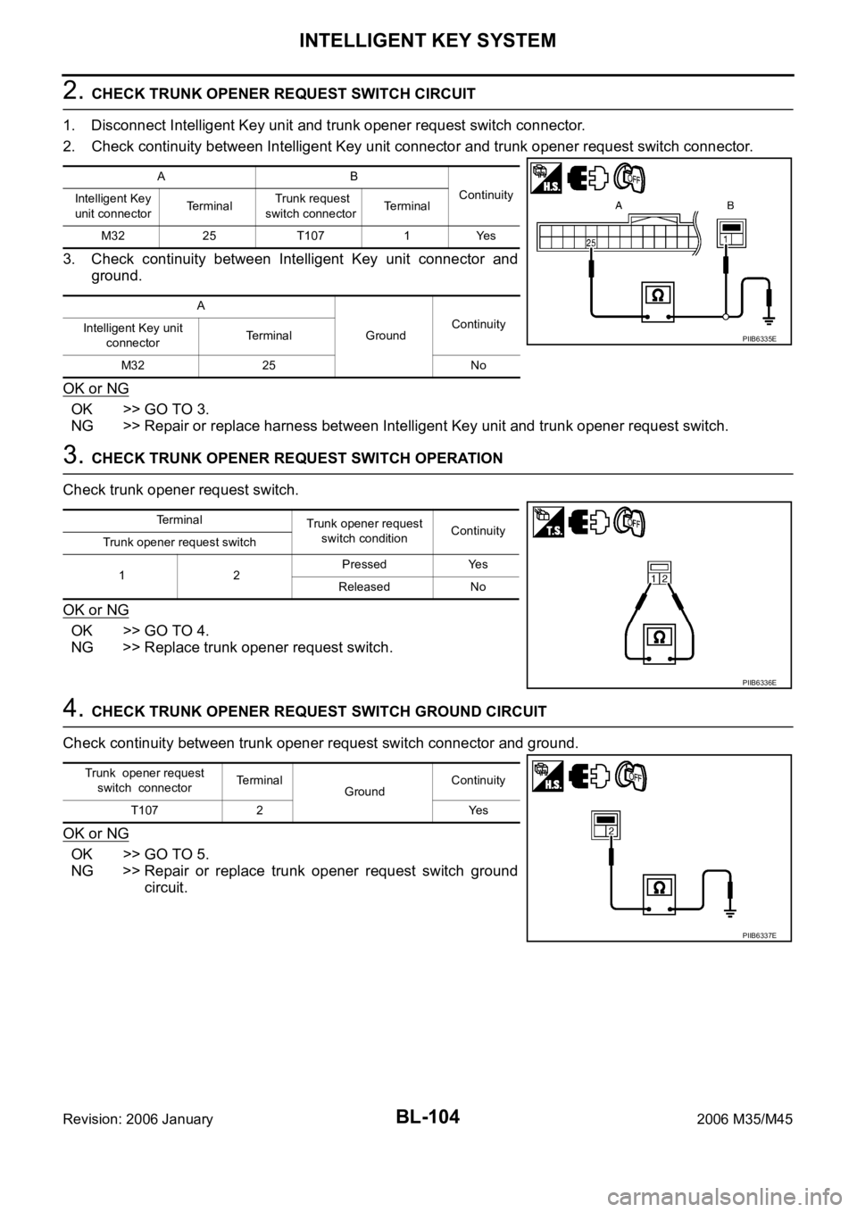
2. CHECK TRUNK OPENER REQUEST SWITCH CIRCUIT
1. Disconnect Intelligent Key unit and trunk opener request switch connector.
2. Check continuity between Intelligent Key unit connector and trunk opener request switch connector.
3. Check continuity between Intelligent Key unit connector and
ground.
OK or NG
OK >> GO TO 3.
NG >> Repair or replace harness between Intelligent Key unit and trunk opener request switch.
3. CHECK TRUNK OPENER REQUEST SWITCH OPERATION
Check trunk opener request switch.
OK or NG
OK >> GO TO 4.
NG >> Replace trunk opener request switch.
4. CHECK TRUNK OPENER REQUEST SWITCH GROUND CIRCUIT
Check continuity between trunk opener request switch connector and ground.
OK or NG
OK >> GO TO 5.
NG >> Repair or replace trunk opener request switch ground
circuit.
AB
Continuity
Intelligent Key
unit connectorTerminal Trunk request
switch connectorTerminal
M32 25 T107 1 Yes
A
GroundContinuity
Intelligent Key unit
connectorTe r m i n a l
M32 25 No
PIIB6335E
Terminal
Trunk opener request
switch conditionContinuity
Trunk opener request switch
12Pressed Yes
Released No
PIIB6336E
Trunk opener request
switch connectorTerminal
GroundContinuity
T107 2 Yes
PIIB6337E
Page 1155 of 5621
BL-216
TRUNK LID OPENER
Revision: 2006 January2006 M35/M45
Trouble DiagnosisNIS001ZS
TRUNK DOSE NOT OPEN WITH TRUNK LID OPENER SWITCH / WITH INTELLIGENT KEY
1. CHECK TRUNK LID OPENER CANCEL SWITCH
Check trunk lid opener cancel switch position.
Does trunk lid opener cancel switch turn OFF (CANCEL)?
Yes >> Turn on trunk lid opener cancel switch.
No >> GO TO 2.
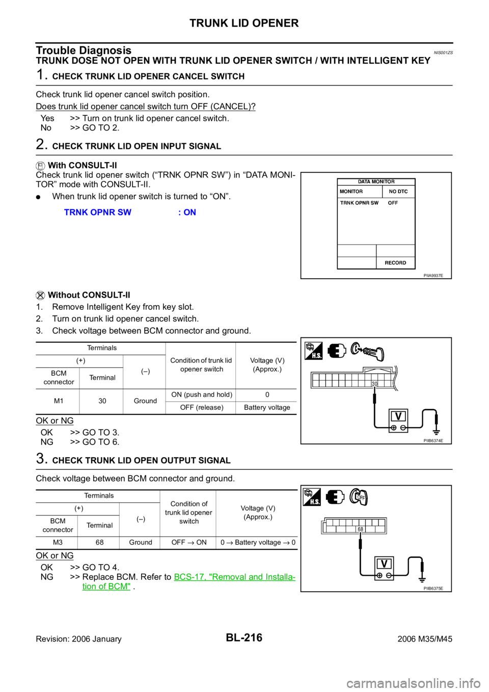
2. CHECK TRUNK LID OPEN INPUT SIGNAL
With CONSULT-II
Check trunk lid opener switch (“TRNK OPNR SW”) in “DATA MONI-
TOR” mode with CONSULT-II.
When trunk lid opener switch is turned to “ON”.
Without CONSULT-II
1. Remove Intelligent Key from key slot.
2. Turn on trunk lid opener cancel switch.
3. Check voltage between BCM connector and ground.
OK or NG
OK >> GO TO 3.
NG >> GO TO 6.
3. CHECK TRUNK LID OPEN OUTPUT SIGNAL
Check voltage between BCM connector and ground.
OK or NG
OK >> GO TO 4.
NG >> Replace BCM. Refer to BCS-17, "
Removal and Installa-
tion of BCM" . TRNK OPNR SW : ON
PIIA9937E
Terminals
Condition of trunk lid
opener switchVoltage (V)
(Approx.) (+)
(–)
BCM
connectorTerminal
M1 30 GroundON (push and hold) 0
OFF (release) Battery voltage
PIIB6374E
Te r m i n a l s
Condition of
trunk lid opener
switchVoltage (V)
(Approx.) (+)
(–)
BCM
connectorTerminal
M3 68 Ground OFF
ON 0 Battery voltage 0
PIIB6375E
Page 1156 of 5621
TRUNK LID OPENER
BL-217
C
D
E
F
G
H
J
K
L
MA
B
BL
Revision: 2006 January2006 M35/M45
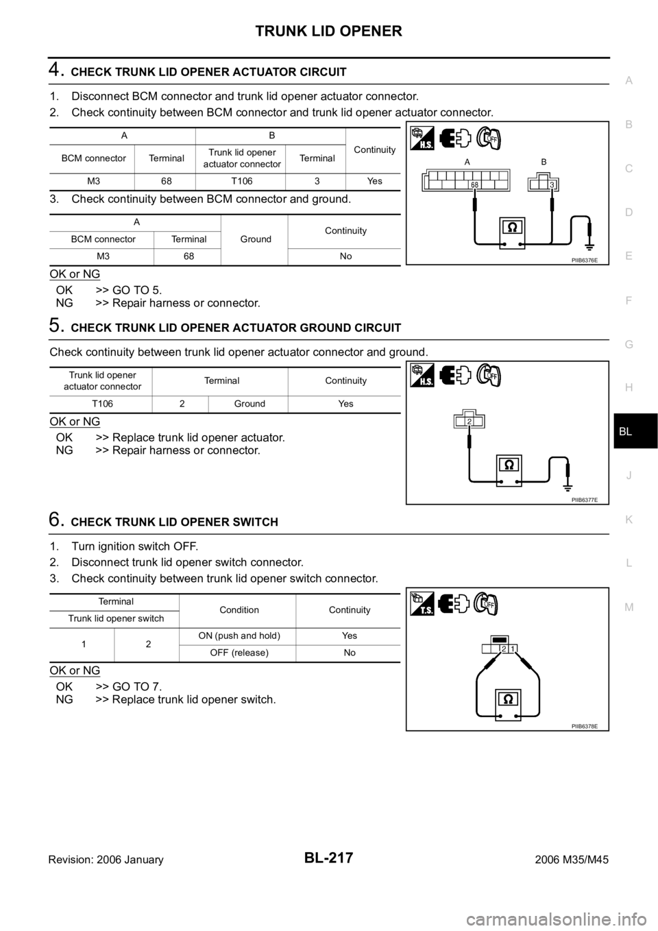
4. CHECK TRUNK LID OPENER ACTUATOR CIRCUIT
1. Disconnect BCM connector and trunk lid opener actuator connector.
2. Check continuity between BCM connector and trunk lid opener actuator connector.
3. Check continuity between BCM connector and ground.
OK or NG
OK >> GO TO 5.
NG >> Repair harness or connector.
5. CHECK TRUNK LID OPENER ACTUATOR GROUND CIRCUIT
Check continuity between trunk lid opener actuator connector and ground.
OK or NG
OK >> Replace trunk lid opener actuator.
NG >> Repair harness or connector.
6. CHECK TRUNK LID OPENER SWITCH
1. Turn ignition switch OFF.
2. Disconnect trunk lid opener switch connector.
3. Check continuity between trunk lid opener switch connector.
OK or NG
OK >> GO TO 7.
NG >> Replace trunk lid opener switch.
AB
Continuity
BCM connector TerminalTrunk lid opener
actuator connectorTerminal
M3 68 T106 3 Yes
A
GroundContinuity
BCM connector Terminal
M3 68 No
PIIB6376E
Trunk lid opener
actuator connectorTerminal Continuity
T106 2 Ground Yes
PIIB6377E
Te r m i n a l
Condition Continuity
Trunk lid opener switch
12ON (push and hold) Yes
OFF (release) No
PIIB6378E
Page 1180 of 5621
VEHICLE SECURITY (THEFT WARNING) SYSTEM
BL-241
C
D
E
F
G
H
J
K
L
MA
B
BL
Revision: 2006 January2006 M35/M45
HOOD SWITCH CHECK
1. CHECK HOOD SWITCH
Check hood switch and hood fitting condition.
OK or NG
OK >> GO TO 2.
NG >> Adjust installation of hood switch.
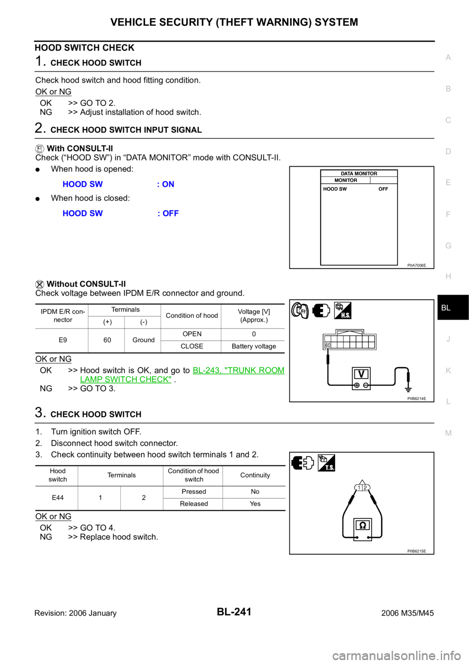
2. CHECK HOOD SWITCH INPUT SIGNAL
With CONSULT-II
Check (“HOOD SW”) in “DATA MONITOR” mode with CONSULT-II.
When hood is opened:
When hood is closed:
Without CONSULT-II
Check voltage between IPDM E/R connector and ground.
OK or NG
OK >> Hood switch is OK, and go to BL-243, "TRUNK ROOM
LAMP SWITCH CHECK" .
NG >> GO TO 3.
3. CHECK HOOD SWITCH
1. Turn ignition switch OFF.
2. Disconnect hood switch connector.
3. Check continuity between hood switch terminals 1 and 2.
OK or NG
OK >> GO TO 4.
NG >> Replace hood switch.HOOD SW : ON
HOOD SW : OFF
PIIA7006E
IPDM E/R con-
nectorTe r m i n a l s
Condition of hoodVoltage [V]
(Approx.)
(+) (-)
E9 60 GroundOPEN 0
CLOSE Battery voltage
PIIB6214E
Hood
switchTerminalsCondition of hood
switchContinuity
E44 1 2Pressed No
Released Yes
PIIB6215E
Page 3483 of 5621
GI-20
HOW TO USE THIS MANUAL
Revision: 2006 January2006 M35/M45
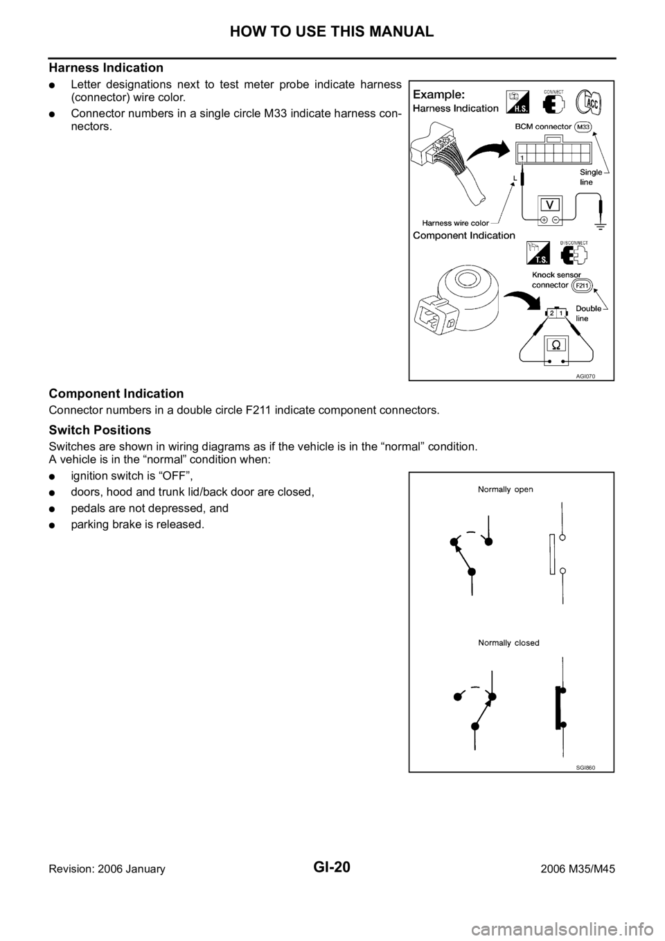
Harness Indication
Letter designations next to test meter probe indicate harness
(connector) wire color.
Connector numbers in a single circle M33 indicate harness con-
nectors.
Component Indication
Connector numbers in a double circle F211 indicate component connectors.
Switch Positions
Switches are shown in wiring diagrams as if the vehicle is in the “normal” condition.
A vehicle is in the “normal” condition when:
ignition switch is “OFF”,
doors, hood and trunk lid/back door are closed,
pedals are not depressed, and
parking brake is released.
AGI070
SGI860
Page 4782 of 5621

GENERAL MAINTENANCE
MA-5
C
D
E
F
G
H
I
J
K
MA
B
MA
Revision: 2006 January2006 M35/M45
OUTSIDE THE VEHICLE
The maintenance items listed here should be performed from time to time, unless otherwise specified.
INSIDE THE VEHICLE
The maintenance items listed here should be checked on a regular basis, such as when performing periodic maintenance, cleaning the
vehicle, etc.ItemReference page
TiresCheck the pressure with a gauge, including the spare, at least once a month
and always prior to a long distance trips. Adjust to the specified pressure if
necessary. Check carefully for damage, cuts or excessive wear.—
Wheel nutsWhen checking the tires, make sure no nuts are missing, and check for any
loose nuts. Tighten if necessary.—
WindshieldClean the windshield on a regular basis. Check the windshield at least every
six months for cracks or other damage. Repair as necessary.—
Tire rotationTires should be rotated every 12,000 km (7,500 miles).MA-35
Wheel alignment and
balanceIf the vehicle pulls to either side while driving on a straight and level road, or if
you detect uneven or abnormal tire wear, there may be a need for wheel align-
ment. If the steering wheel or seat vibrates at normal highway speeds, wheel
balancing may be needed.MA-33,
FSU-6
(2WD),
FSU-23
(AWD)
Windshield wiper
bladesCheck for cracks or wear if they do not wipe properly. —
Doors and engine
hoodCheck that all doors and the engine hood operate smoothly as well as the
trunk lid. Also make sure that all latches lock securely. Lubricate if necessary.
Make sure that the secondary latch keeps the hood from opening when the pri-
mary latch is released.
When driving in areas using road salt or other corrosive materials, check lubri-
cation frequently.MA-38
LampsMake sure that the headlamps, stop lamps, tail lamps, turn signal lamps, and
other lamps are all operating properly and installed securely. Also check head-
lamp aim. Clean the headlamps on a regular basis. —
ItemReference page
Warning lamps and
chimesMake sure that all warning lamps and chimes are operating properly. —
Windshield wiper and
washerCheck that the wipers and washer operate properly and that the wipers do not
streak.—
Windshield defrosterCheck that the air comes out of the defroster outlets properly and in sufficient
quantity when operating the heater or air conditioner.—
Steering wheelCheck that it has the specified play. Be sure to check for changes in the steer-
ing condition, such as excessive play, hard steering or strange noises.
Free play: Less than 35 mm (1.38 in)—
SeatsCheck seat position controls such as seat adjusters, seatback recliner, etc. to
make sure they operate smoothly and that all latches lock securely in every
position. Check that the head restrains move up and down smoothly and that
the locks (if equipped) hold securely in all latched positions. Check that the
latches lock securely for folding-down rear seatbacks.—
Seat beltsCheck that all parts of the seat belt system (e.g. buckles, anchors, adjusters
and retractors) operate properly and smoothly, and are installed securely.
Check the belt webbing for cuts, fraying, wear or damage.MA-39
Accelerator pedalCheck the pedal for smooth operation and make sure the pedal does not catch
or require uneven effort. Keep the floor mats away from the pedal.—
BrakesCheck that the brake does not pull the vehicle to one side when applied. —
Brake pedal and
boosterCheck the pedal for smooth operation and make sure it has the proper dis-
tance under it when depressed fully. Check the brake booster function. Be
sure to keep the floor mats away from the pedal.BR-6
, BR-18