2006 INFINITI M35 fog light
[x] Cancel search: fog lightPage 4523 of 5621

LT-96
HEADLAMP (FOR CANADA) - DAYTIME LIGHT SYSTEM -
Revision: 2006 January2006 M35/M45
NOTE:
This item is displayed, but cannot be monitored.
ACTIVE TEST
Operation Procedure
1. Touch “HEAD LAMP” on “SELECT TEST ITEM” screen.
2. Touch “ACTIVE TEST” on “SELECT DIAG MODE” screen.
3. Touch item to be tested and check operation of the selected item.
4. During the operation check, touching “BACK” deactivates the operation.
Display Item List
DOOR SW - RL “ON/OFF”Displays status of the rear door as judged from the rear door switch (LH) signal. (door is open:
ON/door is closed: OFF)
BACK DOOR SW
NOTE “OFF” —
PKB SW “ON/OFF”Displays status (parking brake released: ON/ parking brake applied: OFF) of parking brake
switch judged from parking brake switch signal.
ENGINE RUN “ON/OFF”Displays status (engine running: ON/ engine stopped: OFF) of engine judged from engine run
signal.
OPTICAL SENSOR “0 - 5V” Displays “outside brightness (close to 5V when light/close to 0V when dark)” judged from opti-
cal sensor signal.
VEHICLE SPEED “km/h” Displays vehicle speed as judged from vehicle speed signal. Monitor item Contents
Test item Description
TAIL LAMP Allows tail lamp relay to operate by switching ON-OFF.
FR FOG LAMP Allows front fog lamp relay to operate by switching ON-OFF.
DAYTIME RUNNING LIGHT Allows daytime relay to operate by switching ON-OFF.
HEAD LAMP (HI, LO) Allows headlamp relay to operate by switching ON-OFF.
Page 4525 of 5621

LT-98
HEADLAMP (FOR CANADA) - DAYTIME LIGHT SYSTEM -
Revision: 2006 January2006 M35/M45
4. Select the desired part to be diagnosed on the “SELECT DIAG
MODE” screen.
DATA MONITOR
Operation Procedure
1. Touch “DATA MONITOR” on “SELECTION DIAG MODE ” screen.
2. Touch “ALL SIGNALS”, “MAIN SIGNALS” or “SELECTION FROM MENU” on the “SELECT MONITOR
ITEM” screen.
3. When “SELECTION FROM MENU” is selected, touch individual items to be monitored. In “ALL SIG-
NALS”, all items are monitored. In “MAIN SIGNALS”, predetermined items are monitored.
4. Touch “START”.
5. Touch “RECORD” while monitoring to record the status of the item being monitored. To stop recording,
touch “STOP”.
All Signals, Main Signals, Selection From Menu
NOTE:
Perform monitoring of IPDM E/R data with the ignition switch ON. When the ignition switch is at ACC, the display may not be correct.
ACTIVE TEST
Operation Procedure
1. Touch “ACTIVE TEST” on “SELECT DIAG MODE” screen.
2. Touch item to be tested, and check operation.
3. Touch “START”.
4. Touch “STOP” while testing to stop the operation.
BCIA0031E
ALL SIGNALS Monitors all items.
MAIN SIGNALS Monitor the predetermined item.
SELECTION FROM MENU Selects items and monitors them.
Item nameCONSULT-II
screen displayDisplay
or unitMonitor item selection
Description
ALL
SIGNALSMAIN
SIGNALSSELECTION
FROM MENU
Position lights request TAIL&CLR REQ ON/OFF
Signal status input from BCM
Headlamp low beam request HL LO REQ ON/OFF
Signal status input from BCM
Headlamp high beam request HL HI REQ ON/OFF
Signal status input from BCM
Front fog lights request FR FOG REQ ON/OFF
Signal status input from BCM
Daytime running light request DTRL REQ ON/OFF
–Signal status input from BCM
Test itemCONSULT-II
screen displayDescription
Tail lamp relay output TAIL LAMP Allows tail lamp relay to operate by switching operation ON-OFF at your option.
Headlamp relay (HI, LO) output
LAMPSAllows headlamp relay (HI, LO) to operate by switching operation (OFF, HI ON, LO
ON) at your option (Headlamp high beam repeats ON-OFF every 1 second).
Front fog lamp relay output Allows fog lamp relay to operate by switching operation ON-OFF at your option.
Page 4556 of 5621

AUTO LIGHT SYSTEM
LT-129
C
D
E
F
G
H
I
J
L
MA
B
LT
Revision: 2006 January2006 M35/M45
DATA MONITOR
Operation Procedure
1. Touch “HEAD LAMP” on “SELECT TEST ITEM” screen.
2. Touch “DATA MONITOR” on “SELECT DIAG MODE” screen.
3. Touch either “ALL SIGNALS” or “SELECTION FROM MENU” on the “SELECT MONITOR ITEM” screen.
4. When “SELECTION FROM MENU” is selected, touch individual items to be monitored. When “ALL SIG-
NALS” is selected, all the items will be monitored.
5. Touch “START”.
6. Touch “RECORD” while monitoring, then the status of the monitored item can be recorded. To stop
recording, touch “STOP”.
Display Item List
NOTE:
This item is displayed, but cannot be monitored.ALL SIGNALS Monitors all the signals.
SELECTION FROM MENU Selects items and monitor them.
Monitor item Contents
IGN ON SW “ON/OFF” Displays “IGN position (ON)/OFF, ACC position (OFF)” judged from the ignition switch signal.
ACC ON SW “ON/OFF” Displays “ACC (ON)/OFF, Ignition OFF (OFF)” status judged from ignition switch signal.
KEY ON SW “ON/OFF”Displays “Intelligent Key inserted into key slot (ON)/Intelligent Key removed from key slot
(OFF)” status judged from the key switch signal.
TURN SIGNAL R “ON/OFF” Displays status (turn right: ON/others: OFF) as judged from lighting switch signal.
TURN SIGNAL L “ON/OFF” Displays status (turn left: ON/others: OFF) as judged from lighting switch signal.
HI BEAM SW “ON/OFF”Displays status (high beam switch: ON/others: OFF) of high beam switch judged from lighting
switch signal.
HEAD LAMP SW 1 “ON/OFF”Displays status (headlamp switch 1: ON/others: OFF) of headlamp switch 1 judged from light-
ing switch signal.
HEAD LAMP SW 2 “ON/OFF”Displays status (headlamp switch 2: ON/others: OFF) of headlamp switch 2 judged from light-
ing switch signal.
TAIL LAMP SW “ON/OFF”Displays status (lighting switch 1ST or 2ND position: ON/others: OFF) of lighting switch judged
from lighting switch signal.
AUTO LIGHT SW “ON/OFF”Displays status of the lighting switch as judged from the lighting switch signal. (AUTO position:
ON/other than AUTO position: OFF)
PASSING SW “ON/OFF”Displays status (flash-to-passing switch: ON/others: OFF) of flash-to-passing switch judged
from lighting switch signal.
FR FOG SW “ON/OFF”Displays status (front fog lamp switch: ON/others: OFF) of front fog lamp switch judged from
lighting switch signal.
DOOR SW - DR “ON/OFF”Displays status of the driver door as judged from the driver door switch signal. (door is open:
ON/door is closed: OFF)
DOOR SW - AS “ON/OFF”Displays status of the passenger door as judged from the passenger door switch signal. (door
is open: ON/door is closed: OFF)
DOOR SW - RR “ON/OFF”Displays status of the rear door as judged from the rear door switch (RH) signal. (door is open:
ON/door is closed: OFF)
DOOR SW - RL “ON/OFF”Displays status of the rear door as judged from the rear door switch (LH) signal. (door is open:
ON/door is closed: OFF)
BACK DOOR SW
NOTE “OFF” —
OPTICAL SENSOR “0 - 5V” Displays “outside brightness (close to 5V when light/close to 0V when dark)” judged from opti-
cal sensor signal.
VEHICLE SPEED “km/h” Displays vehicle speed as judged from vehicle speed signal.
Page 4557 of 5621

LT-130
AUTO LIGHT SYSTEM
Revision: 2006 January2006 M35/M45
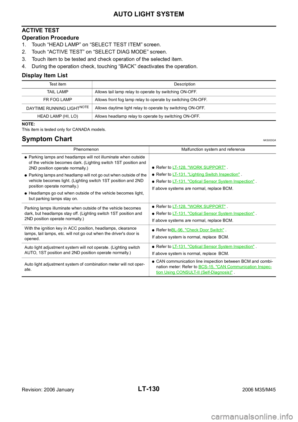
ACTIVE TEST
Operation Procedure
1. Touch “HEAD LAMP” on “SELECT TEST ITEM” screen.
2. Touch “ACTIVE TEST” on “SELECT DIAG MODE” screen.
3. Touch item to be tested and check operation of the selected item.
4. During the operation check, touching “BACK” deactivates the operation.
Display Item List
NOTE:
This item is tested only for CANADA models.
Symptom ChartNKS003QA
Test item Description
TAIL LAMP Allows tail lamp relay to operate by switching ON-OFF.
FR FOG LAMP Allows front fog lamp relay to operate by switching ON-OFF.
DAYTIME RUNNING LIGHT
NOTEAllows daytime light relay to operate by switching ON-OFF.
HEAD LAMP (HI, LO) Allows headlamp relay to operate by switching ON-OFF.
Phenomenon Malfunction system and reference
Parking lamps and headlamps will not illuminate when outside
of the vehicle becomes dark. (Lighting switch 1ST position and
2ND position operate normally.)
Parking lamps and headlamp will not go out when outside of the
vehicle becomes light. (Lighting switch 1ST position and 2ND
position operate normally.)
Headlamps go out when outside of the vehicle becomes light,
but parking lamps stay on.
Refer to LT-128, "WORK SUPPORT" .
Refer to LT-131, "Lighting Switch Inspection" .
Refer to LT-131, "Optical Sensor System Inspection" .
If above systems are normal, replace BCM.
Parking lamps illuminate when outside of the vehicle becomes
dark, but headlamps stay off. (Lighting switch 1ST position and
2ND position operate normally.)
Refer to LT-128, "WORK SUPPORT" .
Refer to LT-131, "Optical Sensor System Inspection" .
If above systems are normal, replace BCM.
With the ignition key in ACC position, headlamps, clearance
lamps, tail lamps, etc. will not go out when the driver's door is
opened.
Refer toBL-96, "Check Door Switch" .
If above system is normal, replace BCM.
Auto light adjustment system will not operate. (Lighting switch
AUTO, 1ST position and 2ND position operate normally.)
Refer to LT-131, "Optical Sensor System Inspection" .
If above system is normal, replace BCM.
Auto light adjustment system of combination meter will not oper-
ate.
CAN communication line inspection between BCM and combi-
nation meter: Refer to BCS-15, "
CAN Communication Inspec-
tion Using CONSULT-II (Self-Diagnosis)" .
Page 4620 of 5621

FRONT FOG LAMP
LT-193
C
D
E
F
G
H
I
J
L
MA
B
LT
Revision: 2006 January2006 M35/M45
FRONT FOG LAMPPFP:26150
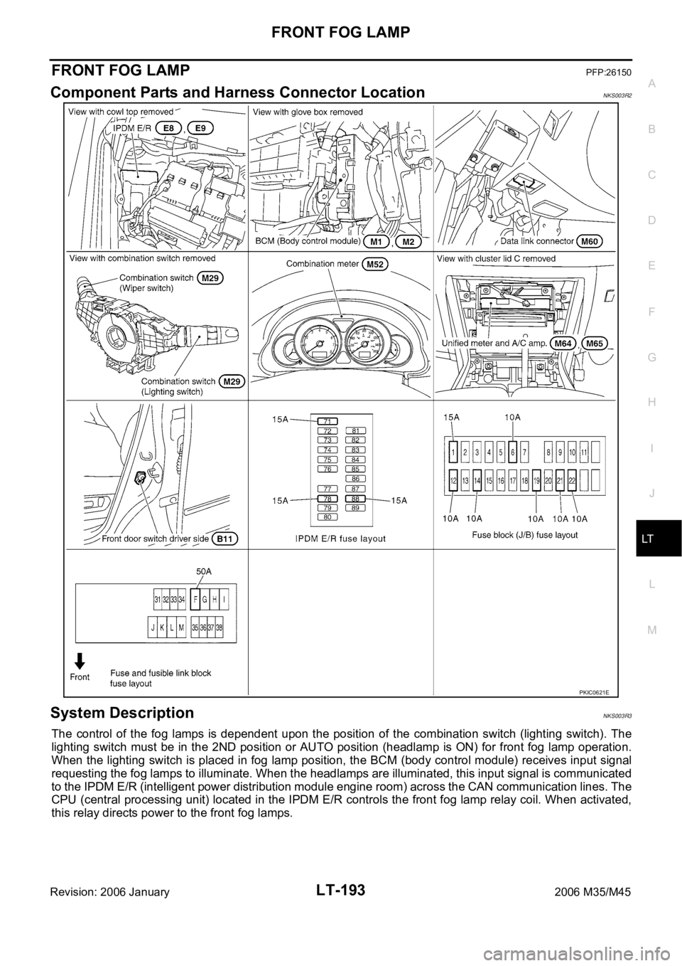
Component Parts and Harness Connector LocationNKS003R2
System DescriptionNKS003R3
The control of the fog lamps is dependent upon the position of the combination switch (lighting switch). The
lighting switch must be in the 2ND position or AUTO position (headlamp is ON) for front fog lamp operation.
When the lighting switch is placed in fog lamp position, the BCM (body control module) receives input signal
requesting the fog lamps to illuminate. When the headlamps are illuminated, this input signal is communicated
to the IPDM E/R (intelligent power distribution module engine room) across the CAN communication lines. The
CPU (central processing unit) located in the IPDM E/R controls the front fog lamp relay coil. When activated,
this relay directs power to the front fog lamps.
PKIC0621E
Page 4622 of 5621

FRONT FOG LAMP
LT-195
C
D
E
F
G
H
I
J
L
MA
B
LT
Revision: 2006 January2006 M35/M45
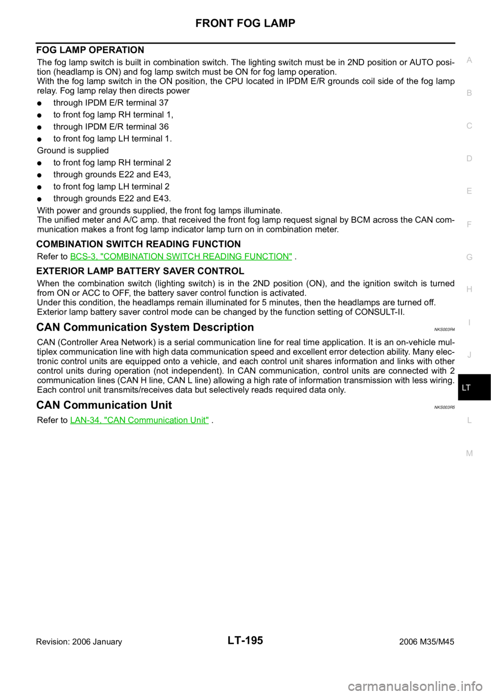
FOG LAMP OPERATION
The fog lamp switch is built in combination switch. The lighting switch must be in 2ND position or AUTO posi-
tion (headlamp is ON) and fog lamp switch must be ON for fog lamp operation.
With the fog lamp switch in the ON position, the CPU located in IPDM E/R grounds coil side of the fog lamp
relay. Fog lamp relay then directs power
through IPDM E/R terminal 37
to front fog lamp RH terminal 1,
through IPDM E/R terminal 36
to front fog lamp LH terminal 1.
Ground is supplied
to front fog lamp RH terminal 2
through grounds E22 and E43,
to front fog lamp LH terminal 2
through grounds E22 and E43.
With power and grounds supplied, the front fog lamps illuminate.
The unified meter and A/C amp. that received the front fog lamp request signal by BCM across the CAN com-
munication makes a front fog lamp indicator lamp turn on in combination meter.
COMBINATION SWITCH READING FUNCTION
Refer to BCS-3, "COMBINATION SWITCH READING FUNCTION" .
EXTERIOR LAMP BATTERY SAVER CONTROL
When the combination switch (lighting switch) is in the 2ND position (ON), and the ignition switch is turned
from ON or ACC to OFF, the battery saver control function is activated.
Under this condition, the headlamps remain illuminated for 5 minutes, then the headlamps are turned off.
Exterior lamp battery saver control mode can be changed by the function setting of CONSULT-II.
CAN Communication System DescriptionNKS003R4
CAN (Controller Area Network) is a serial communication line for real time application. It is an on-vehicle mul-
tiplex communication line with high data communication speed and excellent error detection ability. Many elec-
tronic control units are equipped onto a vehicle, and each control unit shares information and links with other
control units during operation (not independent). In CAN communication, control units are connected with 2
communication lines (CAN H line, CAN L line) allowing a high rate of information transmission with less wiring.
Each control unit transmits/receives data but selectively reads required data only.
CAN Communication UnitNKS003R5
Refer to LAN-34, "CAN Communication Unit" .
Page 4628 of 5621

FRONT FOG LAMP
LT-201
C
D
E
F
G
H
I
J
L
MA
B
LT
Revision: 2006 January2006 M35/M45
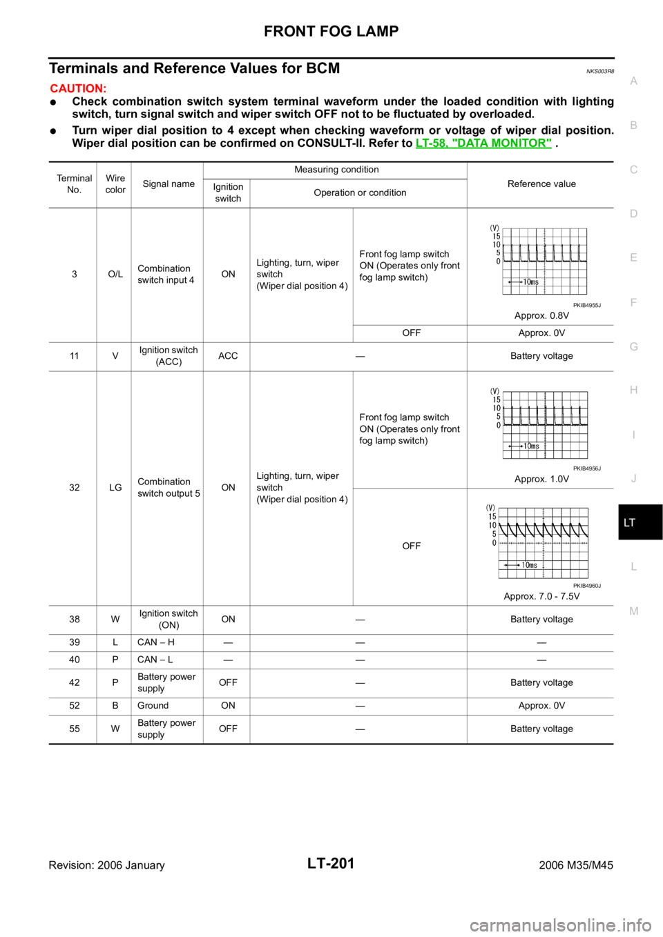
Terminals and Reference Values for BCMNKS003R8
CAUTION:
Check combination switch system terminal waveform under the loaded condition with lighting
switch, turn signal switch and wiper switch OFF not to be fluctuated by overloaded.
Turn wiper dial position to 4 except when checking waveform or voltage of wiper dial position.
Wiper dial position can be confirmed on CONSULT-II. Refer to LT- 5 8 , "
DATA MONITOR" .
Terminal
No.Wire
colorSignal nameMeasuring condition
Reference value
Ignition
switchOperation or condition
3O/LCombination
switch input 4ONLighting, turn, wiper
switch
(Wiper dial position 4)Front fog lamp switch
ON (Operates only front
fog lamp switch)
Approx. 0.8V
OFF Approx. 0V
11 VIgnition switch
(ACC)ACC — Battery voltage
32 LGCombination
switch output 5ONLighting, turn, wiper
switch
(Wiper dial position 4)Front fog lamp switch
ON (Operates only front
fog lamp switch)
Approx. 1.0V
OFF
Approx. 7.0 - 7.5V
38 WIgnition switch
(ON) ON — Battery voltage
39 L CAN
H — — —
40 P CAN
L — — —
42 PBattery power
supplyOFF — Battery voltage
52 B Ground ON — Approx. 0V
55 WBattery power
supplyOFF — Battery voltage
PKIB4955J
PKIB4956J
PKIB4960J
Page 4629 of 5621

LT-202
FRONT FOG LAMP
Revision: 2006 January2006 M35/M45
Terminals and Reference Values for IPDM E/RNKS003R9
How to Perform Trouble DiagnosesNKS003RA
1. Confirm the symptom or customer complaint.
2. Understand operation description and function description. Refer to LT- 1 9 3 , "
System Description" .
3. Perform the Preliminary Check. Refer to LT-202, "
Preliminary Check" .
4. Check symptom and repair or replace the cause of malfunction.
5. Does the front fog lamp operate normally? If YES, GO TO 6. If NO, GO TO 4.
6. INSPECTION END
Preliminary CheckNKS003RB
CHECK POWER SUPPLY AND GROUND CIRCUIT
1. CHECK FUSE
Check for blown fuses.
Refer to LT-197, "Wiring Diagram — F/FOG —" .
OK or NG
OK >> GO TO 2.
NG >> If fuse or fusible link is blown, be sure to eliminate cause of malfunction before installing new fuse
or fusible link. Refer to PG-3, "
POWER SUPPLY ROUTING CIRCUIT" .
Terminal
No.Wire
colorSignal nameMeasuring condition
Reference value
Ignition
switchOperation or condition
36 L/Y Front fog lamp (LH) ONLighting switch must be in
the 2ND position or AUTO
position (headlamp is ON)Front fog lamp switch: OFF Approx. 0V
Front fog lamp switch: ON Battery voltage
37 W/R Front fog lamp (RH) ONLighting switch must be in
the 2ND position or AUTO
position (headlamp is ON)Front fog lamp switch: OFF Approx. 0V
Front fog lamp switch: ON Battery voltage
38 B Ground ON — Approx. 0V
49 L CAN
H — — —
50 P CAN
L — — —
51 B Ground ON — Approx. 0V
Unit Power source Fuse and fusible link No.
BCMBatteryF
21
Ignition switch ON or START position 1
Ignition switch ACC or ON position 6
IPDM E/R Battery71
88
78