2006 INFINITI M35 fog light
[x] Cancel search: fog lightPage 4631 of 5621
LT-204
FRONT FOG LAMP
Revision: 2006 January2006 M35/M45
Front Fog Lamps Do Not Illuminate (Both Sides)NKS003RE
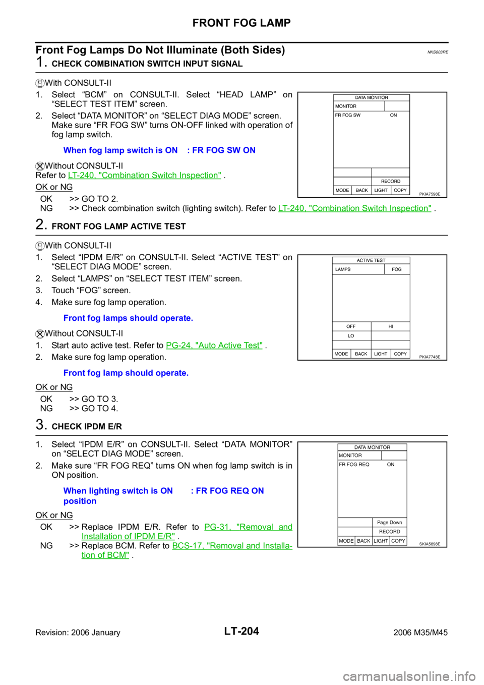
1. CHECK COMBINATION SWITCH INPUT SIGNAL
With CONSULT-II
1. Select “BCM” on CONSULT-II. Select “HEAD LAMP” on
“SELECT TEST ITEM” screen.
2. Select “DATA MONITOR” on “SELECT DIAG MODE” screen.
Make sure “FR FOG SW” turns ON-OFF linked with operation of
fog lamp switch.
Without CONSULT-II
Refer to LT- 2 4 0 , "
Combination Switch Inspection" .
OK or NG
OK >> GO TO 2.
NG >> Check combination switch (lighting switch). Refer to LT-240, "
Combination Switch Inspection" .
2. FRONT FOG LAMP ACTIVE TEST
With CONSULT-II
1. Select “IPDM E/R” on CONSULT-II. Select “ACTIVE TEST” on
“SELECT DIAG MODE” screen.
2. Select “LAMPS” on “SELECT TEST ITEM” screen.
3. Touch “FOG” screen.
4. Make sure fog lamp operation.
Without CONSULT-II
1. Start auto active test. Refer to PG-24, "
Auto Active Test" .
2. Make sure fog lamp operation.
OK or NG
OK >> GO TO 3.
NG >> GO TO 4.
3. CHECK IPDM E/R
1. Select “IPDM E/R” on CONSULT-II. Select “DATA MONITOR”
on “SELECT DIAG MODE” screen.
2. Make sure “FR FOG REQ” turns ON when fog lamp switch is in
ON position.
OK or NG
OK >> Replace IPDM E/R. Refer to PG-31, "Removal and
Installation of IPDM E/R" .
NG >> Replace BCM. Refer to BCS-17, "
Removal and Installa-
tion of BCM" . When fog lamp switch is ON : FR FOG SW ON
PKIA7598E
Front fog lamps should operate.
Front fog lamp should operate.
PKIA7748E
When lighting switch is ON
position: FR FOG REQ ON
SKIA5898E
Page 4635 of 5621
LT-208
FRONT FOG LAMP
Revision: 2006 January2006 M35/M45
4. CHECK FOG LAMP CIRCUIT
1. Turn ignition switch OFF.
2. Disconnect IPDM E/R connector.
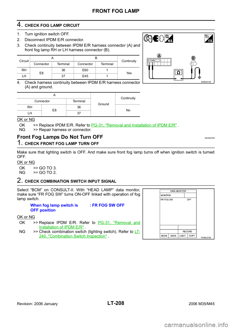
3. Check continuity between IPDM E/R harness connector (A) and
front fog lamp RH or LH harness connector (B).
4. Check harness continuity between IPDM E/R harness connector
(A) and ground.
OK or NG
OK >> Replace IPDM E/R. Refer to PG-31, "Removal and Installation of IPDM E/R" .
NG >> Repair harness or connector.
Front Fog Lamps Do Not Turn OFFNKS003RG
1. CHECK FRONT FOG LAMP TURN OFF
Make sure that lighting switch is OFF. And make sure front fog lamp turns off when ignition switch is turned
OFF.
OK or NG
OK >> GO TO 3.
NG >> GO TO 2.
2. CHECK COMBINATION SWITCH INPUT SIGNAL
Select “BCM” on CONSULT-II. With “HEAD LAMP” data monitor,
make sure “FR FOG SW” turns ON-OFF linked with operation of fog
lamp switch.
OK or NG
OK >> Replace IPDM E/R. Refer to PG-31, "Removal and
Installation of IPDM E/R" .
NG >> Check combination switch (lighting switch). Refer to LT-
240, "Combination Switch Inspection" .
CircuitAB
Continuity
Connector Terminal Connector Terminal
RH
E836 E60 1
Ye s
LH 37 E45 1
A
GroundContinuity
Connector Terminal
RH
E836
No
LH 37
SKIB4815E
When fog lamp switch is
OFF position: FR FOG SW OFF
PKIB9378E
Page 4637 of 5621
LT-210
FRONT FOG LAMP
Revision: 2006 January2006 M35/M45
Bulb ReplacementNKS003RI
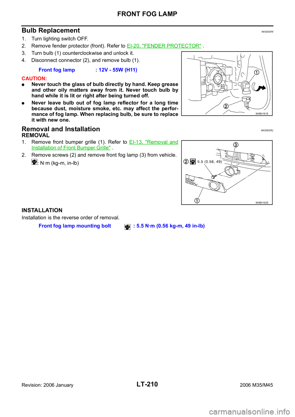
1. Turn lighting switch OFF.
2. Remove fender protector (front). Refer to EI-20, "
FENDER PROTECTOR" .
3. Turn bulb (1) counterclockwise and unlock it.
4. Disconnect connector (2), and remove bulb (1).
CAUTION:
Never touch the glass of bulb directly by hand. Keep grease
and other oily matters away from it. Never touch bulb by
hand while it is lit or right after being turned off.
Never leave bulb out of fog lamp reflector for a long time
because dust, moisture smoke, etc. may affect the perfor-
mance of fog lamp. When replacing bulb, be sure to replace
it with new one.
Removal and InstallationNKS003RJ
REMOVAL
1. Remove front bumper grille (1). Refer to EI-13, "Removal and
Installation of Front Bumper Grille" .
2. Remove screws (2) and remove front fog lamp (3) from vehicle.
: Nꞏm (kg-m, in-lb)
INSTALLATION
Installation is the reverse order of removal.Front fog lamp : 12V - 55W (H11)
SKIB4161E
SKIB4162E
Front fog lamp mounting bolt : 5.5 Nꞏm (0.56 kg-m, 49 in-lb)
Page 4660 of 5621
COMBINATION SWITCH
LT-233
C
D
E
F
G
H
I
J
L
MA
B
LT
Revision: 2006 January2006 M35/M45
Combination Switch Reading FunctionNKS003S6
For details, refer to BCS-3, "COMBINATION SWITCH READING FUNCTION" .
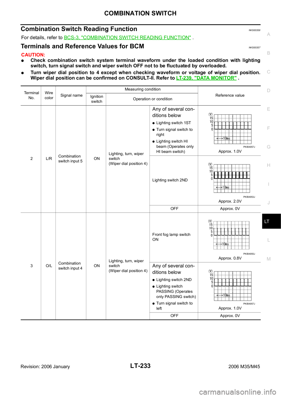
Terminals and Reference Values for BCMNKS003S7
CAUTION:
Check combination switch system terminal waveform under the loaded condition with lighting
switch, turn signal switch and wiper switch OFF not to be fluctuated by overloaded.
Turn wiper dial position to 4 except when checking waveform or voltage of wiper dial position.
Wiper dial position can be confirmed on CONSULT-II. Refer to LT-239, "
DATA MONITOR" .
Terminal
No.Wire
colorSignal nameMeasuring condition
Reference value
Ignition
switchOperation or condition
2L/RCombination
switch input 5ONLighting, turn, wiper
switch
(Wiper dial position 4)
Any of several con-
ditions below
Lighting switch 1ST
Turn signal switch to
right
Lighting switch HI
beam (Operates only
HI beam switch)Approx. 1.0V
Lighting switch 2ND
Approx. 2.0V
OFF Approx. 0V
3O/LCombination
switch input 4ONLighting, turn, wiper
switch
(Wiper dial position 4)Front fog lamp switch
ON
Approx. 0.8V
Any of several con-
ditions below
Lighting switch 2ND
Lighting switch
PASSING (Operates
only PASSING switch)
Turn signal switch to
leftApprox. 1.0V
OFF Approx. 0V
PKIB4957J
PKIB4953J
PKIB4955J
PKIB4957J
Page 4662 of 5621

COMBINATION SWITCH
LT-235
C
D
E
F
G
H
I
J
L
MA
B
LT
Revision: 2006 January2006 M35/M45
32 LGCombination
switch output 5ONLighting, turn, wiper
switch
Any of several con-
ditions below
Front fog lamp switch
(Operates only front
fog lamp switch)
(Wiper dial position 4)
Wiper dial position 1
Wiper dial position 2
Wiper dial position 6
Wiper dial position 7Approx. 1.0V
OFF
(Wiper dial position 4)
Approx. 7.0 - 7.5V
33 GRCombination
switch output 4ONLighting, turn, wiper
switch
Any of several con-
ditions below
Lighting switch AUTO
(Wiper dial position 4)
Lighting switch 1ST
(The same result with
lighting switch 2ND)
(Wiper dial position 4)
Wiper dial position 1
Wiper dial position 5
Wiper dial position 6Approx. 1.2V
OFF
(Wiper dial position 4)
Approx. 7.0 - 7.5V Terminal
No.Wire
colorSignal nameMeasuring condition
Reference value
Ignition
switchOperation or condition
PKIB4956J
PKIB4960J
PKIB4958J
PKIB4960J
Page 4666 of 5621

COMBINATION SWITCH
LT-239
C
D
E
F
G
H
I
J
L
MA
B
LT
Revision: 2006 January2006 M35/M45
DATA MONITOR
Operation Procedure
1. Touch “COMB SW” on “SELECT TEST ITEM” screen.
2. Touch “DATA MONITOR” on “SELECT DIAG MODE” screen.
3. Touch either “ALL SIGNALS” or “SELECTION FROM MENU” on “SELECT MONITOR ITEM” screen.
4. When “SELECTION FROM MENU” is selected, touch items to be monitored. When “ALL SIGNALS” is
selected, all the signals will be monitored.
5. Touch “START”.
6. Touch “RECORD” while monitoring, then the status of the monitored item can be recorded. To stop
recording, touch “STOP”.
Display Item List
ALL SIGNALS Monitors all the signals.
SELECTION FROM MENU Selects items and monitor them.
Monitor item name Contents
TURN SIGNAL R “ON/OFF” Displays “turn right (ON)/other (OFF)” status, determined from lighting switch signal.
TURN SIGNAL L “ON/OFF” Displays “turn left (ON)/other (OFF)” status, determined from lighting switch signal.
HI BEAM SW “ON/OFF”Displays status (high beam switch: ON/others: OFF) of high beam switch judged from lighting
switch signal.
HEAD LAMP SW 1 “ON/OFF”Displays status (headlamp switch 1: ON/others: OFF) of headlamp switch 1 judged from lighting
switch signal.
HEAD LAMP SW 2 “ON/OFF”Displays status (headlamp switch 2: ON/others: OFF) of headlamp switch 2 judged from lighting
switch signal.
TAIL LAMP SW “ON/OFF”Displays status (lighting switch 1ST or 2ND position: ON/others: OFF) of lighting switch judged from
lighting switch signal.
PASSING SW “ON/OFF”Displays status (flash-to-pass switch: ON/others: OFF) of flash-to-pass switch judged from lighting
switch signal.
AUTO LIGHT SW “ON/OFF” Displays “auto light switch (ON)/other (OFF)” status, determined from lighting switch signal.
FR FOG SW “ON/OFF” Displays “front fog lamp switch (ON)/other (OFF)” status, determined from lighting switch signal.
FR WIPER HI “ON/OFF” Displays “front wiper HI (ON)/other (OFF)” status, determined from wiper switch signal.
FR WIPER LOW “ON/OFF” Displays “front wiper LOW (ON)/other (OFF)” status, determined from wiper switch signal.
FR WIPER INT “ON/OFF” Displays “front wiper INT (ON)/other (OFF)” status, determined from wiper switch signal.
FR WASHER SW “ON/OFF” Displays “front washer switch (ON)/other (OFF)” status, determined from wiper switch signal.
INT VOLUME “1 - 7” Displays intermittent operation knob setting (1 - 7), determined from wiper switch signal.
Page 4667 of 5621
LT-240
COMBINATION SWITCH
Revision: 2006 January2006 M35/M45
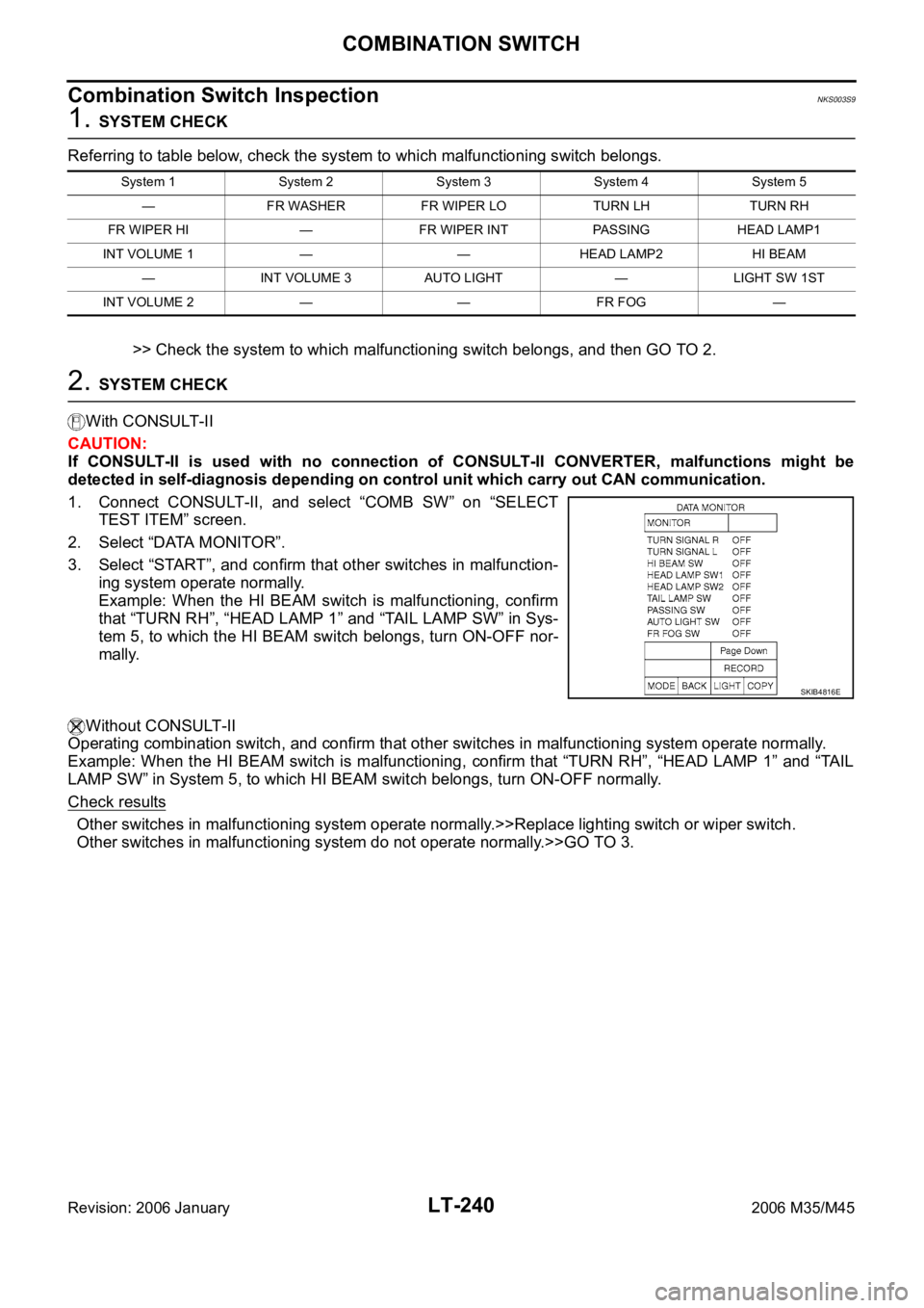
Combination Switch InspectionNKS003S9
1. SYSTEM CHECK
Referring to table below, check the system to which malfunctioning switch belongs.
>> Check the system to which malfunctioning switch belongs, and then GO TO 2.
2. SYSTEM CHECK
With CONSULT-II
CAUTION:
If CONSULT-II is used with no connection of CONSULT-II CONVERTER, malfunctions might be
detected in self-diagnosis depending on control unit which carry out CAN communication.
1. Connect CONSULT-II, and select “COMB SW” on “SELECT
TEST ITEM” screen.
2. Select “DATA MONITOR”.
3. Select “START”, and confirm that other switches in malfunction-
ing system operate normally.
Example: When the HI BEAM switch is malfunctioning, confirm
that “TURN RH”, “HEAD LAMP 1” and “TAIL LAMP SW” in Sys-
tem 5, to which the HI BEAM switch belongs, turn ON-OFF nor-
mally.
Without CONSULT-II
Operating combination switch, and confirm that other switches in malfunctioning system operate normally.
Example: When the HI BEAM switch is malfunctioning, confirm that “TURN RH”, “HEAD LAMP 1” and “TAIL
LAMP SW” in System 5, to which HI BEAM switch belongs, turn ON-OFF normally.
Check results
Other switches in malfunctioning system operate normally.>>Replace lighting switch or wiper switch.
Other switches in malfunctioning system do not operate normally.>>GO TO 3.
System 1 System 2 System 3 System 4 System 5
— FR WASHER FR WIPER LO TURN LH TURN RH
FR WIPER HI — FR WIPER INT PASSING HEAD LAMP1
INT VOLUME 1 — — HEAD LAMP2 HI BEAM
— INT VOLUME 3 AUTO LIGHT — LIGHT SW 1ST
INT VOLUME 2 — — FR FOG —
SKIB4816E
Page 4724 of 5621

ILLUMINATION
LT-297
C
D
E
F
G
H
I
J
L
MA
B
LT
Revision: 2006 January2006 M35/M45
to door mirror remote control switch (illumination) terminal 15
to AFS switch (illumination) terminal 6 (with AFS)
to rear sunshade front switch (illumination) terminal 6 (with rear control switch)
to A/T illumination terminal 2
to snow mode switch (illumination) terminal 6 (ADW models)
to rear control cancel switch (illumination) terminal 5 (with rear control switch)
to clock terminal 4
to multifunction switch terminal 4
to audio unit terminal 8
to DVD player terminal 17 (With DVD player)
to climate controlled seat switch driver side (illumination) terminal 8 (with climate controlled seat) and
to climate controlled seat switch passenger side (illumination) terminal 8 (with climate controlled seat)
through illumination control switch terminal 2
to illumination control switch terminal 3
through grounds M16 and M70,
to cigarette lighter socket (illumination) terminal 1
to map lamp (illumination) terminal 4
to power window main switch illumination terminal 2 and
to glove box lamp terminal 2
through grounds M16 and M70,
to ashtray illumination (rear LH) terminal 2
to ashtray illumination (rear RH) terminal 2
to automatic return cancel switch (illumination) terminal 2 (With rear control switch)
to rear power seat switch LH (illumination) terminal 3 (With rear control switch)
to rear heated seat switch LH (illumination) terminal 8 (With rear control switch)
through grounds B5, B40 and B131,
through rear sunshade cancel relay terminal 7(With rear control switch)
to rear sunshade rear switch (illumination) terminal 7 (With rear control switch)
through grounds B5, B40, B131 and B559.
to rear control switch terminal 4
to rear power seat switch RH (illumination) terminal 3 (With rear control switch)
to rear heated seat switch RH (illumination) terminal 8 (With rear control switch)
through grounds B5, B40, B131 and B559.
With power and ground supplied, illumination lamps illuminate.
EXTERIOR LAMP BATTERY SAVER CONTROL
BCM activates the exterior lamp battery saver control function and turns off the exterior lamps to prevent bat-
tery from over discharge when the combination switch (lighting switch) is in 1ST or 2ND position and/or the
front fog lamp switch ON and the door lock operation is performed by keyless entry system.
CAN Communication System DescriptionNKS003TI
CAN (Controller Area Network) is a serial communication line for real time application. It is an on-vehicle mul-
tiplex communication line with high data communication speed and excellent error detection ability. Many elec-
tronic control units are equipped onto a vehicle, and each control unit shares information and links with other
control units during operation (not independent). In CAN communication, control units are connected with 2
communication lines (CAN H line, CAN L line) allowing a high rate of information transmission with less wiring.
Each control unit transmits/receives data but selectively reads required data only.
CAN Communication UnitNKS003TJ
Refer to LAN-34, "CAN Communication Unit" .