Page 4985 of 5621
PS-32
POWER STEERING OIL PUMP
Revision: 2006 January2006 M35/M45
ASSEMBLY
NOTE:
Secure oil pump in a vise if necessary.
CAUTION:
Use copper plates when securing in a vise.
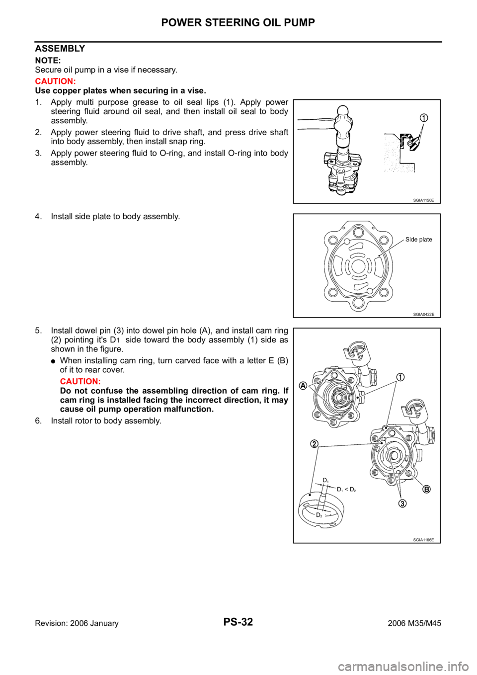
1. Apply multi purpose grease to oil seal lips (1). Apply power
steering fluid around oil seal, and then install oil seal to body
assembly.
2. Apply power steering fluid to drive shaft, and press drive shaft
into body assembly, then install snap ring.
3. Apply power steering fluid to O-ring, and install O-ring into body
assembly.
4. Install side plate to body assembly.
5. Install dowel pin (3) into dowel pin hole (A), and install cam ring
(2) pointing it's D
1 side toward the body assembly (1) side as
shown in the figure.
When installing cam ring, turn carved face with a letter E (B)
of it to rear cover.
CAUTION:
Do not confuse the assembling direction of cam ring. If
cam ring is installed facing the incorrect direction, it may
cause oil pump operation malfunction.
6. Install rotor to body assembly.
SGIA1150E
SGIA0422E
SGIA1166E
Page 4988 of 5621
POWER STEERING OIL PUMP
PS-35
C
D
E
F
H
I
J
K
L
MA
B
PS
Revision: 2006 January2006 M35/M45
DISASSEMBLY
NOTE:
Secure oil pump in a vise if necessary.
CAUTION:
Use copper plates when securing in a vise.
1. Remove rear cover mounting bolts, and then remove rear cover from body assembly.
2. Remove O-ring from body assembly.
3. Remove rear side plate from cartridge, and then remove Teflon ring and O-ring from rear side plate.
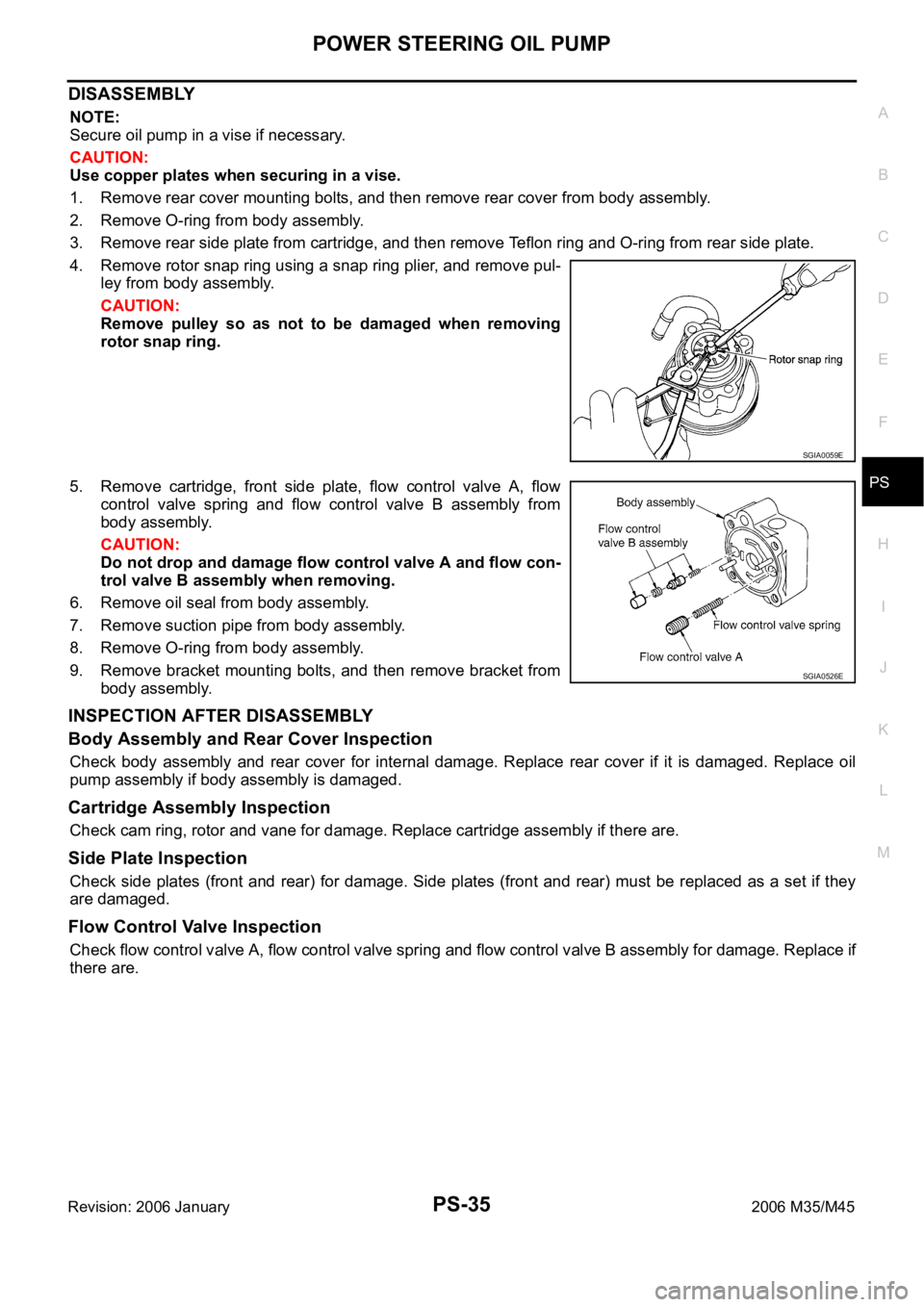
4. Remove rotor snap ring using a snap ring plier, and remove pul-
ley from body assembly.
CAUTION:
Remove pulley so as not to be damaged when removing
rotor snap ring.
5. Remove cartridge, front side plate, flow control valve A, flow
control valve spring and flow control valve B assembly from
body assembly.
CAUTION:
Do not drop and damage flow control valve A and flow con-
trol valve B assembly when removing.
6. Remove oil seal from body assembly.
7. Remove suction pipe from body assembly.
8. Remove O-ring from body assembly.
9. Remove bracket mounting bolts, and then remove bracket from
body assembly.
INSPECTION AFTER DISASSEMBLY
Body Assembly and Rear Cover Inspection
Check body assembly and rear cover for internal damage. Replace rear cover if it is damaged. Replace oil
pump assembly if body assembly is damaged.
Cartridge Assembly Inspection
Check cam ring, rotor and vane for damage. Replace cartridge assembly if there are.
Side Plate Inspection
Check side plates (front and rear) for damage. Side plates (front and rear) must be replaced as a set if they
are damaged.
Flow Control Valve Inspection
Check flow control valve A, flow control valve spring and flow control valve B assembly for damage. Replace if
there are.
SGIA0059E
SGIA0526E
Page 4989 of 5621
PS-36
POWER STEERING OIL PUMP
Revision: 2006 January2006 M35/M45
ASSEMBLY
NOTE:
Secure oil pump in a vise if necessary.
CAUTION:
Use copper plates when securing in a vise.
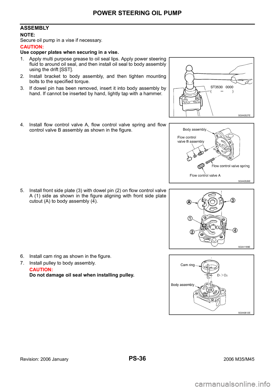
1. Apply multi purpose grease to oil seal lips. Apply power steering
fluid to around oil seal, and then install oil seal to body assembly
using the drift [SST].
2. Install bracket to body assembly, and then tighten mounting
bolts to the specified torque.
3. If dowel pin has been removed, insert it into body assembly by
hand. If cannot be inserted by hand, lightly tap with a hammer.
4. Install flow control valve A, flow control valve spring and flow
control valve B assembly as shown in the figure.
5. Install front side plate (3) with dowel pin (2) on flow control valve
A (1) side as shown in the figure aligning with front side plate
cutout (A) to body assembly (4).
6. Install cam ring as shown in the figure.
7. Install pulley to body assembly.
CAUTION:
Do not damage oil seal when installing pulley.
SGIA0527E
SGIA0526E
SGIA1189E
SGIA0612E
Page 4991 of 5621
PS-38
HYDRAULIC LINE
Revision: 2006 January2006 M35/M45
HYDRAULIC LINEPFP:49721
ComponentsNGS000DI
CAUTION:
Securely insert harness connector to pressure sensor.
VQ35DE 2WD MODELS
SGIA1390E
Page 4996 of 5621
HYDRAULIC LINE
PS-43
C
D
E
F
H
I
J
K
L
MA
B
PS
Revision: 2006 January2006 M35/M45
Removal and InstallationNGS000DL
Insert hose securely until it contacts tube spool.
CAUTION:
Do not apply fluid.
Install eye-bolt with eye-joint (assembled to high-pressure hose)
protrusion facing with pump side cutout, and then tighten it to
the specified torque after tightening by hand.
Refer to GI-11, "Components" , and the followings for the symbols in the figure.
: Apply power steering fluid.
SGIA0514E
SGIA0515E
Page 5008 of 5621
REAR DRIVE SHAFT
RAX-9
C
E
F
G
H
I
J
K
L
MA
B
RAX
Revision: 2006 January2006 M35/M45
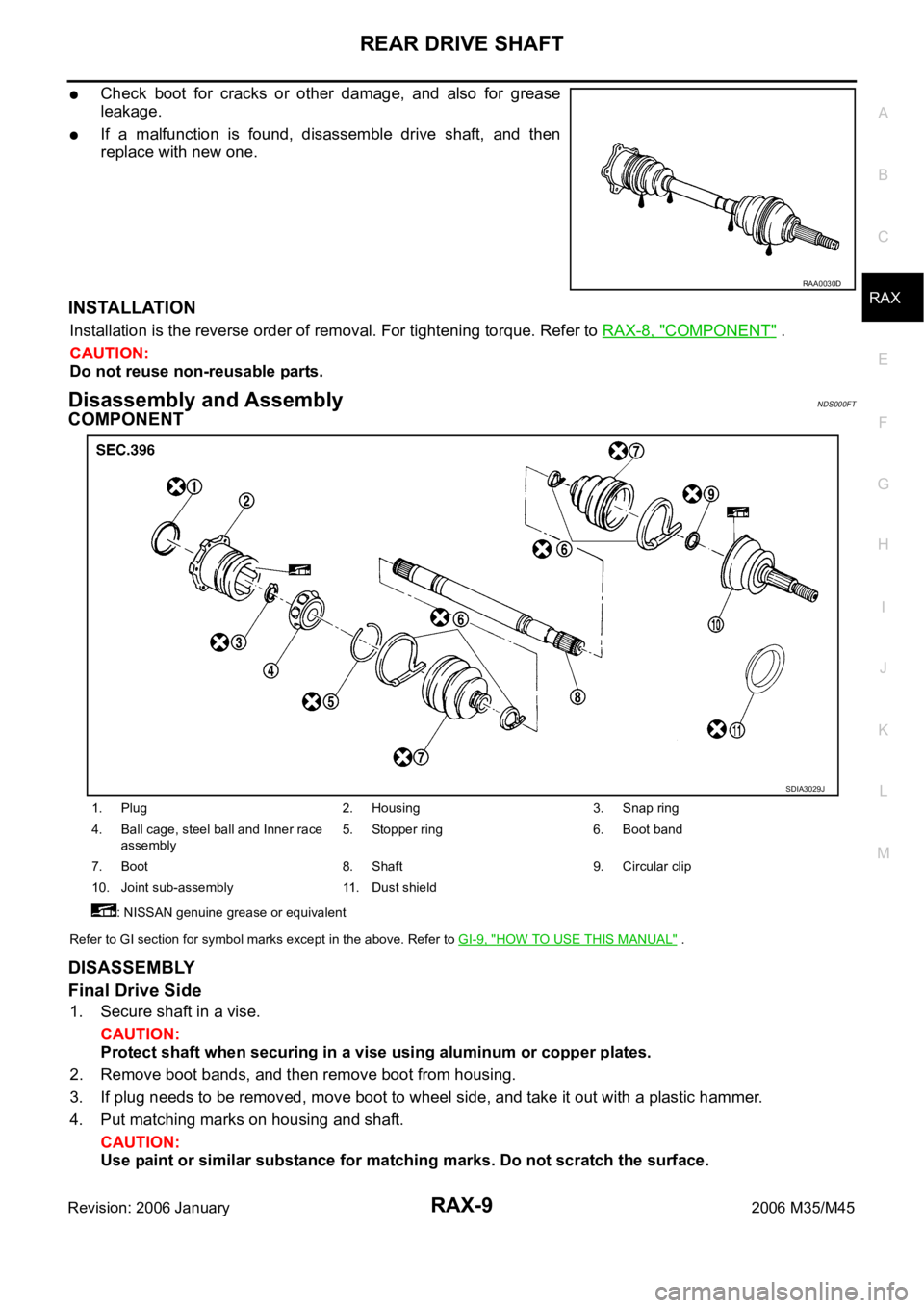
Check boot for cracks or other damage, and also for grease
leakage.
If a malfunction is found, disassemble drive shaft, and then
replace with new one.
INSTALLATION
Installation is the reverse order of removal. For tightening torque. Refer to RAX-8, "COMPONENT" .
CAUTION:
Do not reuse non-reusable parts.
Disassembly and AssemblyNDS000FT
COMPONENT
Refer to GI section for symbol marks except in the above. Refer to GI-9, "HOW TO USE THIS MANUAL" .
DISASSEMBLY
Final Drive Side
1. Secure shaft in a vise.
CAUTION:
Protect shaft when securing in a vise using aluminum or copper plates.
2. Remove boot bands, and then remove boot from housing.
3. If plug needs to be removed, move boot to wheel side, and take it out with a plastic hammer.
4. Put matching marks on housing and shaft.
CAUTION:
Use paint or similar substance for matching marks. Do not scratch the surface.
RAA0030D
1. Plug 2. Housing 3. Snap ring
4. Ball cage, steel ball and Inner race
assembly5. Stopper ring 6. Boot band
7. Boot 8. Shaft 9. Circular clip
10. Joint sub-assembly 11. Dust shield
: NISSAN genuine grease or equivalent
SDIA3029J
Page 5009 of 5621
RAX-10
REAR DRIVE SHAFT
Revision: 2006 January2006 M35/M45
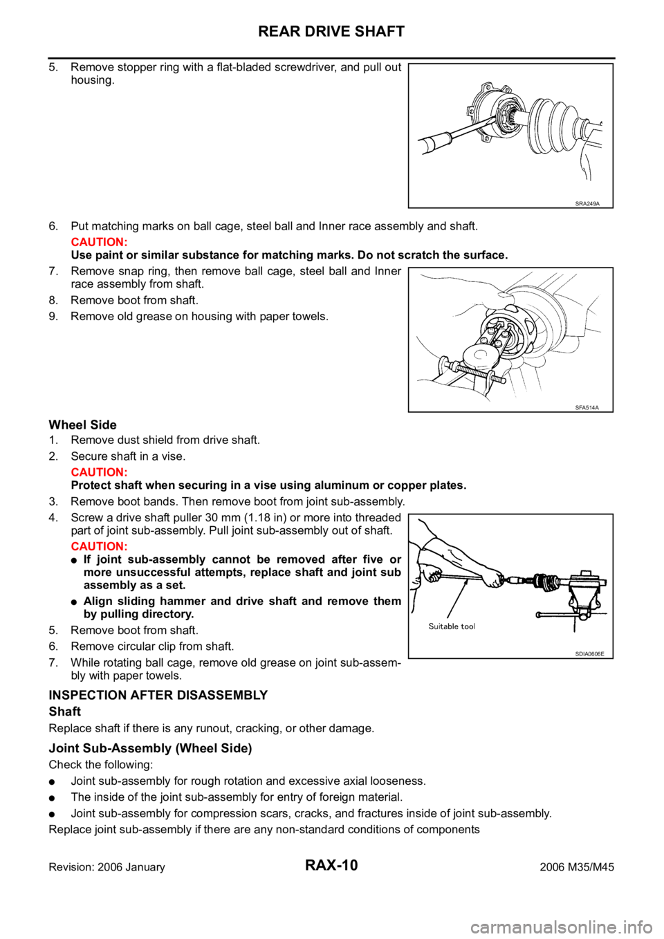
5. Remove stopper ring with a flat-bladed screwdriver, and pull out
housing.
6. Put matching marks on ball cage, steel ball and Inner race assembly and shaft.
CAUTION:
Use paint or similar substance for matching marks. Do not scratch the surface.
7. Remove snap ring, then remove ball cage, steel ball and Inner
race assembly from shaft.
8. Remove boot from shaft.
9. Remove old grease on housing with paper towels.
Wheel Side
1. Remove dust shield from drive shaft.
2. Secure shaft in a vise.
CAUTION:
Protect shaft when securing in a vise using aluminum or copper plates.
3. Remove boot bands. Then remove boot from joint sub-assembly.
4. Screw a drive shaft puller 30 mm (1.18 in) or more into threaded
part of joint sub-assembly. Pull joint sub-assembly out of shaft.
CAUTION:
If joint sub-assembly cannot be removed after five or
more unsuccessful attempts, replace shaft and joint sub
assembly as a set.
Align sliding hammer and drive shaft and remove them
by pulling directory.
5. Remove boot from shaft.
6. Remove circular clip from shaft.
7. While rotating ball cage, remove old grease on joint sub-assem-
bly with paper towels.
INSPECTION AFTER DISASSEMBLY
Shaft
Replace shaft if there is any runout, cracking, or other damage.
Joint Sub-Assembly (Wheel Side)
Check the following:
Joint sub-assembly for rough rotation and excessive axial looseness.
The inside of the joint sub-assembly for entry of foreign material.
Joint sub-assembly for compression scars, cracks, and fractures inside of joint sub-assembly.
Replace joint sub-assembly if there are any non-standard conditions of components
SRA249A
SFA514A
SDIA0606E
Page 5010 of 5621
REAR DRIVE SHAFT
RAX-11
C
E
F
G
H
I
J
K
L
MA
B
RAX
Revision: 2006 January2006 M35/M45
CAUTION:
If there are any irregular conditions of joint sub-assembly components, replace the entire joint sub-
assembly.
Final Drive Side
Make sure there are compression scars, cracks, fractures or unusual wear of ball rolling surface.
Make sure there is no damage to shaft screws.
Make sure there is no deformation of boot installation parts.
Ball Cage
Make sure there are compression scars, cracks, fractures of sliding surface.
Steel Ball
Make sure there are compression scars, cracks, fractures or unusual wear.
Inner Race
Check ball sliding surface for compression scars, cracks or fractures.
Make sure there is no damage to serrated part.
CAUTION:
If there are any irregular conditions in the component, replace with a new set of housing and the
ball cage, steel ball and inner race assembly.
ASSEMBLY
Final Drive Side
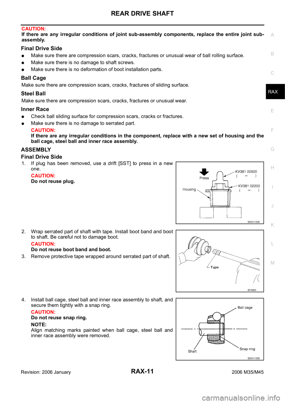
1. If plug has been removed, use a drift [SST] to press in a new
one.
CAUTION:
Do not reuse plug.
2. Wrap serrated part of shaft with tape. Install boot band and boot
to shaft. Be careful not to damage boot.
CAUTION:
Do not reuse boot band and boot.
3. Remove protective tape wrapped around serrated part of shaft.
4. Install ball cage, steel ball and inner race assembly to shaft, and
secure them tightly with a snap ring.
CAUTION:
Do not reuse snap ring.
NOTE:
Align matching marks painted when ball cage, steel ball and
inner race assembly were removed.
SDIA1153E
SFA800
SDIA1125E