2006 INFINITI M35 ECU
[x] Cancel search: ECUPage 5091 of 5621
RSU-10
SHOCK ABSORBER
Revision: 2006 January2006 M35/M45
SHOCK ABSORBERPFP:56210
Removal and InstallationNES000JA
REMOVAL
1. Remove tires from vehicle with a power tool.
2. Set a jack under rear lower link to relieve the coil spring tension.
3. Remove shock absorber lower end bolt with a power tool.
4. Gradually lower the jack to remove it from rear lower link.
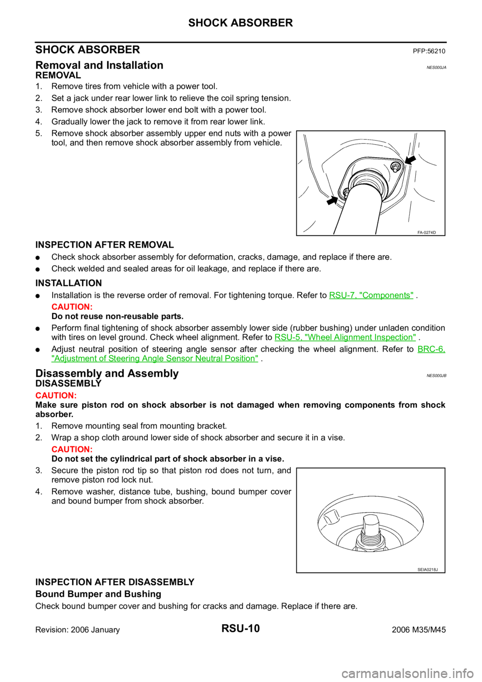
5. Remove shock absorber assembly upper end nuts with a power
tool, and then remove shock absorber assembly from vehicle.
INSPECTION AFTER REMOVAL
Check shock absorber assembly for deformation, cracks, damage, and replace if there are.
Check welded and sealed areas for oil leakage, and replace if there are.
INSTALLATION
Installation is the reverse order of removal. For tightening torque. Refer to RSU-7, "Components" .
CAUTION:
Do not reuse non-reusable parts.
Perform final tightening of shock absorber assembly lower side (rubber bushing) under unladen condition
with tires on level ground. Check wheel alignment. Refer to RSU-5, "
Wheel Alignment Inspection" .
Adjust neutral position of steering angle sensor after checking the wheel alignment. Refer to BRC-6,
"Adjustment of Steering Angle Sensor Neutral Position" .
Disassembly and AssemblyNES000JB
DISASSEMBLY
CAUTION:
Make sure piston rod on shock absorber is not damaged when removing components from shock
absorber.
1. Remove mounting seal from mounting bracket.
2. Wrap a shop cloth around lower side of shock absorber and secure it in a vise.
CAUTION:
Do not set the cylindrical part of shock absorber in a vise.
3. Secure the piston rod tip so that piston rod does not turn, and
remove piston rod lock nut.
4. Remove washer, distance tube, bushing, bound bumper cover
and bound bumper from shock absorber.
INSPECTION AFTER DISASSEMBLY
Bound Bumper and Bushing
Check bound bumper cover and bushing for cracks and damage. Replace if there are.
FA-0274D
SEIA0218J
Page 5097 of 5621
RSU-16
REAR LOWER LINK & COIL SPRING
Revision: 2006 January2006 M35/M45
REAR LOWER LINK & COIL SPRINGPFP:551B0
Removal and InstallationNES000JF
REMOVAL
1. Remove tire with a power tool.
2. Set a jack under rear lower link to relieve the coil spring tension.
3. Loosen mounting bolt and nut of rear lower link inside of suspension member, and then remove mounting
bolt and nut inside of axle with a power tool.
4. Slowly lower jack, then remove upper seat, coil spring and rubber sheet from rear lower link.
5. Remove mounting bolt and nut inside of suspension member to remove rear lower link with a power tool.
INSPECTION AFTER REMOVAL
Check rear lower link, bushing and coil spring for deformation, cracks, and damage. Replace rear lower link
and coil spring if there are.
INSTALLATION
Installation is the reverse order of removal. For tightening torque. Refer to RSU-7, "Components" .
CAUTION:
Do not reuse non-reusable parts.
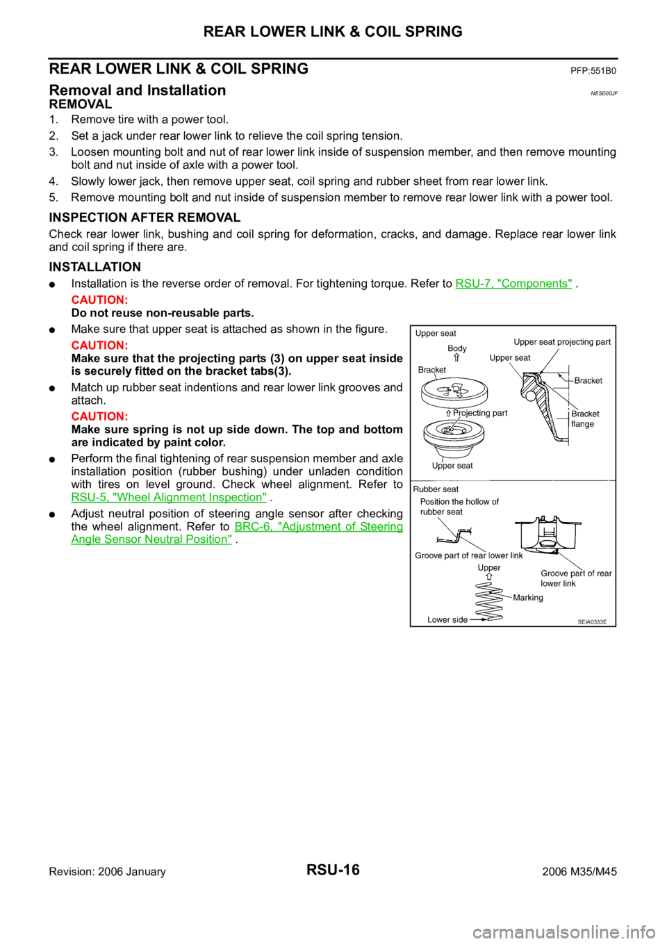
Make sure that upper seat is attached as shown in the figure.
CAUTION:
Make sure that the projecting parts (3) on upper seat inside
is securely fitted on the bracket tabs(3).
Match up rubber seat indentions and rear lower link grooves and
attach.
CAUTION:
Make sure spring is not up side down. The top and bottom
are indicated by paint color.
Perform the final tightening of rear suspension member and axle
installation position (rubber bushing) under unladen condition
with tires on level ground. Check wheel alignment. Refer to
RSU-5, "
Wheel Alignment Inspection" .
Adjust neutral position of steering angle sensor after checking
the wheel alignment. Refer to BRC-6, "
Adjustment of Steering
Angle Sensor Neutral Position" .
SEIA0333E
Page 5102 of 5621
PRE-CRASH SEAT BELT
SB-3
C
D
E
F
G
I
J
K
L
MA
B
SB
Revision: 2006 January2006 M35/M45
PRE-CRASH SEAT BELTPFP:98845
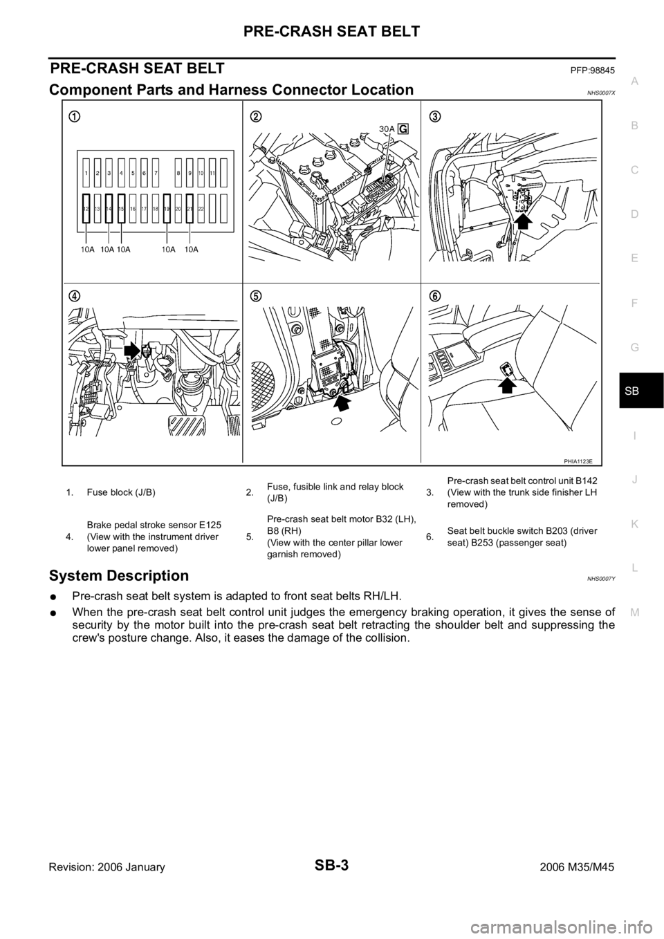
Component Parts and Harness Connector LocationNHS0007X
System DescriptionNHS0007Y
Pre-crash seat belt system is adapted to front seat belts RH/LH.
When the pre-crash seat belt control unit judges the emergency braking operation, it gives the sense of
security by the motor built into the pre-crash seat belt retracting the shoulder belt and suppressing the
crew's posture change. Also, it eases the damage of the collision.
PHIA1123E
1. Fuse block (J/B) 2.Fuse, fusible link and relay block
(J/B)3.Pre-crash seat belt control unit B142
(View with the trunk side finisher LH
removed)
4.Brake pedal stroke sensor E125
(View with the instrument driver
lower panel removed)5.Pre-crash seat belt motor B32 (LH),
B8 (RH)
(View with the center pillar lower
garnish removed)6.Seat belt buckle switch B203 (driver
seat) B253 (passenger seat)
Page 5113 of 5621
SB-14
PRE-CRASH SEAT BELT
Revision: 2006 January2006 M35/M45
CONSULT-II Function (PRECRASH SEATBELT)NHS00085
CONSULT-II can display each diagnostic item using the diagnostic test modes shown following.
CONSULT-II INSPECTION PROCEDURE
CAUTION:
If CONSULT-II is used with no connection of CONSULT-II CONVERTER, malfunctions might be
detected in self-diagnosis depending on control unit which carry out CAN communication.
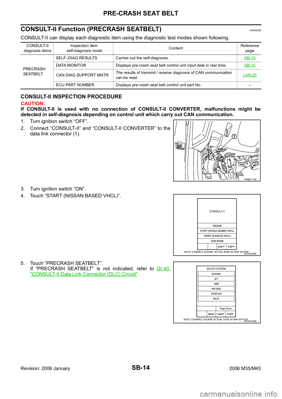
1. Turn ignition switch “OFF”.
2. Connect “CONSULT-II” and “CONSULT-II CONVERTER” to the
data link connector (1).
3. Turn ignition switch “ON”.
4. Touch “START (NISSAN BASED VHCL)”.
5. Touch “PRECRASH SEATBELT”.
If “PRECRASH SEATBELT” is not indicated, refer to GI-40,
"CONSULT-II Data Link Connector (DLC) Circuit" .
CONSULT-II
diagnosis itemsInspection item
self-diagnosis modeContentReference
page
PRECRASH
SEATBELTSELF–DIAG RESULTS Carries out the self-diagnosis.SB-15
DATA MONITOR Displays pre-crash seat belt control unit input data in real time.SB-15
CAN DIAG SUPPORT MNTRThe results of transmit / receive diagnosis of CAN communication
can be read.LAN-20
ECU PART NUMBER Displays pre-crash seat belt control unit part No. –
PBIB2712E
BCIA0029E
BCIA0030E
Page 5114 of 5621
PRE-CRASH SEAT BELT
SB-15
C
D
E
F
G
I
J
K
L
MA
B
SB
Revision: 2006 January2006 M35/M45
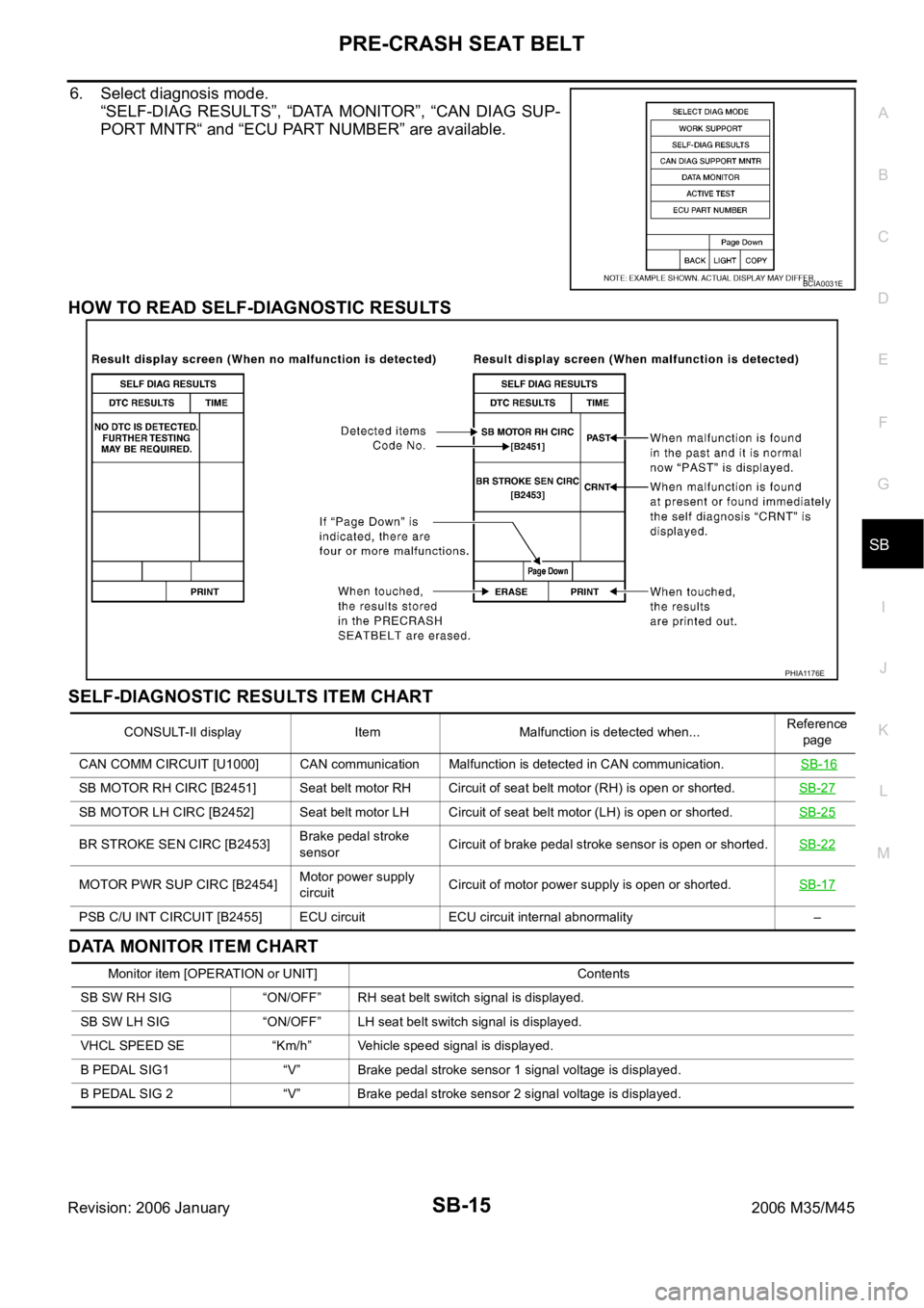
6. Select diagnosis mode.
“SELF-DIAG RESULTS”, “DATA MONITOR”, “CAN DIAG SUP-
PORT MNTR“ and “ECU PART NUMBER” are available.
HOW TO READ SELF-DIAGNOSTIC RESULTS
SELF-DIAGNOSTIC RESULTS ITEM CHART
DATA MONITOR ITEM CHART
BCIA0031E
PHIA1176E
CONSULT-II display Item Malfunction is detected when...Reference
page
CAN COMM CIRCUIT [U1000] CAN communication Malfunction is detected in CAN communication. SB-16
SB MOTOR RH CIRC [B2451] Seat belt motor RH Circuit of seat belt motor (RH) is open or shorted.SB-27
SB MOTOR LH CIRC [B2452] Seat belt motor LH Circuit of seat belt motor (LH) is open or shorted.SB-25
BR STROKE SEN CIRC [B2453]Brake pedal stroke
sensorCircuit of brake pedal stroke sensor is open or shorted.SB-22
MOTOR PWR SUP CIRC [B2454]Motor power supply
circuitCircuit of motor power supply is open or shorted.SB-17
PSB C/U INT CIRCUIT [B2455] ECU circuit ECU circuit internal abnormality –
Monitor item [OPERATION or UNIT] Contents
SB SW RH SIG “ON/OFF” RH seat belt switch signal is displayed.
SB SW LH SIG “ON/OFF” LH seat belt switch signal is displayed.
VHCL SPEED SE “Km/h” Vehicle speed signal is displayed.
B PEDAL SIG1 “V” Brake pedal stroke sensor 1 signal voltage is displayed.
B PEDAL SIG 2 “V” Brake pedal stroke sensor 2 signal voltage is displayed.
Page 5132 of 5621
SEAT BELTS
SB-33
C
D
E
F
G
I
J
K
L
MA
B
SB
Revision: 2006 January2006 M35/M45
INSTALLATION OF SEAT BELT BUCKLE
Install in the reverse order of removal.
Tighten by specified torque.
Seat Belt InspectionNHS0008L
AFTER A COLLISION
WAR NING :
Inspect all seat belt assemblies including retractors and attaching hardware after any collision.
NISSAN / INFINITI recommends that all seat belt assemblies in use during a collision be replaced
unless the collision was minor and the belts show no damage and continue to operate properly. Fail-
ure to do so could result in serious personal injury in an accident. Seat belt assemblies not in use dur-
ing a collision should also be replaced if either damage or improper operation is noted. Seat belt pre-
tensioned should be replaced even if the seat belts are not in use during a frontal collision in which
the air bags are deployed.
Replace any seat belt assembly (including anchor bolts) if:
The seat belt was in use at the time of a collision (except for minor collisions and the belts, retractors and
buckles show no damage and continue to operate properly).
The seat belt was damaged in an accident. (i.e. torn webbing, bent retractor or guide, etc.)
The seat belt attaching point was damaged in an accident. Inspect the seat belt attaching area for damage
or distortion and repair as necessary before installing a new seat belt assembly.
Anchor bolts are deformed or worn out.
The seat belt pre-tensioner should be replaced even if the seat belts are not in use during the collision in
which the air bags are deployed.
PRELIMINARY CHECKS
1. Check the seat belt warning lamp/chime for proper operation as follows:
a. Switch ignition ON. The seat belt warning lamp should illuminate. Also, the seat belt warning chime should
sound for about six seconds.
b. Fasten driver's seat belt. The seat belt warning lamp should go out and the chime (if sounding) should
stop.
2. If the air bag warning lamp is blinking, conduct self-diagnosis using CONSULT-II, and air bag warning
lamp. Refer to SRS-19, "
SRS Operation Check" .
3. Check that the seat belt retractor, seat belt anchor and buckle bolts are securely attached.
4. Check the shoulder seat belt guide and shoulder belt height adjuster for front seats. Ensure guide swivels
freely and that webbing lays flat and does not bind in guide. Ensure height adjuster operates properly and
holds securely.
5. Check retractor operation:
a. Fully extend the seat belt webbing and check for twists, tears or other damage.
b. Allow the seat belt to retract. Ensure that webbing returns smoothly and completely into the retractor. If
the seat belt does not return smoothly, wipe the inside of the loops with a clean paper cloth. Because dirt
built up in the loops of the upper anchors can cause the seat belts to retract slowly.
c. Fasten the seat belt. Check the seat belt returns smoothly and completely to the retractor. If the webbing
does not return smoothly, the cause may be an accumulation of dust or dirt. Use the “SEAT BELT TAPE
SET” and perform the following steps.
Inspect the front seat belt though-anchor
1. Pull the seat belt out to a length of 500 mm (19.69 in) or more.
2. Use a clip or other device to the fix the seat belt at the center pillar webbing opening.
3. Pass a thin wire though the though-anchor webbing opening. Hold both ends of the wire and pull it
tantly while moving it up and down several times along the webbing opening surface to move matter
stuck there.
4. Any dirt that can not be removed with the wire can be removed by cleaning the opening with a clean
cloth.
5. Apply tape at the point where the webbing contacts the though-anchor webbing opening. Tightening torque : 49.0 Nꞏm (5.0 kg-m, 36 ft-lb)
Page 5184 of 5621

PRECAUTIONS
SE-3
C
D
E
F
G
H
J
K
L
MA
B
SE
Revision: 2006 January2006 M35/M45
PRECAUTIONSPFP:00001
Precautions for Supplemental Restraint System (SRS) “AIR BAG” and “SEAT
BELT PRE-TENSIONER”
NIS0025I
The Supplemental Restraint System such as “AIR BAG” and “SEAT BELT PRE-TENSIONER”, used along
with a front seat belt, helps to reduce the risk or severity of injury to the driver and front passenger for certain
types of collision. This system includes seat belt switch inputs and dual stage front air bag modules. The SRS
system uses the seat belt switches to determine the front air bag deployment, and may only deploy one front
air bag, depending on the severity of a collision and whether the front occupants are belted or unbelted.
Information necessary to service the system safely is included in the SRS and SB section of this Service Man-
ual.
WAR NING :
To avoid rendering the SRS inoperative, which could increase the risk of personal injury or death
in the event of a collision which would result in air bag inflation, all maintenance must be per-
formed by an authorized NISSAN/INFINITI dealer.
Improper maintenance, including incorrect removal and installation of the SRS, can lead to per-
sonal injury caused by unintentional activation of the system. For removal of Spiral Cable and Air
Bag Module, see the SRS section.
Do not use electrical test equipment on any circuit related to the SRS unless instructed to in this
Service Manual. SRS wiring harnesses can be identified by yellow and/or orange harnesses or
harness connectors.
Service NoticeNIS0025J
When removing or installing various parts, place a cloth or padding onto the vehicle body to prevent
scratches.
Handle trim, molding, instruments, grille, etc. carefully during removing or installing. Be careful not to oil or
damage them.
Apply sealing compound where necessary when installing parts.
When applying sealing compound, be careful that the sealing compound does not protrude from parts.
When replacing any metal parts (for example body outer panel, members, etc.), be sure to take rust pre-
vention measures.
Precautions for WorkNIS0025K
When removing or disassembling each component, be careful not to damage or deform it. If a component
may be subject to interference, be sure to protect it with a shop cloth.
When removing (disengaging) components with a screwdriver or similar tool, be sure to wrap the compo-
nent with a shop cloth or vinyl tape to protect it.
Protect the removed parts with a shop cloth and keep them.
Replace a deformed or damaged clip.
If a part is specified as a non-reusable part, always replace it with new one.
Be sure to tighten bolts and nuts securely to the specified torque.
After re-installation is completed, be sure to check that each part works normally.
Follow the steps below to clean components.
–Water soluble foul: Dip a soft cloth into lukewarm water, and wring the water out of the cloth to wipe the
fouled area.
Then rub with a soft and dry cloth.
–Oily foul: Dip a soft cloth into lukewarm water with mild detergent (concentration: within 2 to 3%), and wipe
the fouled area.
Then dip a cloth into fresh water, and wring the water out of the cloth to wipe the detergent off. Then rub
with a soft and dry cloth.
Do not use organic solvent such as thinner, benzene, alcohol, and gasoline.
For genuine leather seats, use a genuine leather seat cleaner.
Page 5187 of 5621
SE-6
SQUEAK AND RATTLE TROUBLE DIAGNOSES
Revision: 2006 January2006 M35/M45
DUPLICATE THE NOISE AND TEST DRIVE
If possible, drive the vehicle with the customer until the noise is duplicated. Note any additional information on
the Diagnostic Worksheet regarding the conditions or location of the noise. This information can be used to
duplicate the same conditions when you confirm the repair.
If the noise can be duplicated easily during the test drive, to help identify the source of the noise, try to dupli-
cate the noise with the vehicle stopped by doing one or all of the following:
1) Close a door.
2) Tap or push/pull around the area where the noise appears to be coming from.
3) Rev the engine.
4) Use a floor jack to recreate vehicle “twist”.
5) At idle, apply engine load (electrical load, half-clutch on M/T models, drive position on A/T models).
6) Raise the vehicle on a hoist and hit a tire with a rubber hammer.
Drive the vehicle and attempt to duplicate the conditions the customer states exist when the noise occurs.
If it is difficult to duplicate the noise, drive the vehicle slowly on an undulating or rough road to stress the
vehicle body.
CHECK RELATED SERVICE BULLETINS
After verifying the customer concern or symptom, check ASIST for Technical Service Bulletins (TSBs) related
to that concern or symptom.
If a TSB relates to the symptom, follow the procedure to repair the noise.
LOCATE THE NOISE AND IDENTIFY THE ROOT CAUSE
1. Narrow down the noise to a general area. To help pinpoint the source of the noise, use a listening tool
(Chassis Ear: J-39570, Engine Ear and mechanics stethoscope).
2. Narrow down the noise to a more specific area and identify the cause of the noise by:
removing the components in the area that you suspect the noise is coming from.
Do not use too much force when removing clips and fasteners, otherwise clips and fastener can be broken
or lost during the repair, resulting in the creation of new noise.
tapping or pushing/pulling the component that you suspect is causing the noise.
Do not tap or push/pull the component with excessive force, otherwise the noise will be eliminated only
temporarily.
feeling for a vibration with your hand by touching the component(s) that you suspect is (are) causing the
noise.
placing a piece of paper between components that you suspect are causing the noise.
looking for loose components and contact marks.
Refer to SE-7, "
Generic Squeak and Rattle Troubleshooting" .
REPAIR THE CAUSE
If the cause is a loose component, tighten the component securely.
If the cause is insufficient clearance between components:
–separate components by repositioning or loosening and retightening the component, if possible.
–insulate components with a suitable insulator such as urethane pads, foam blocks, felt cloth tape or ure-
thane tape. A Nissan Squeak and Rattle Kit (J-43980) is available through your authorized Nissan Parts
Department.
CAUTION:
Do not use excessive force as many components are constructed of plastic and may be damaged.
NOTE:
Always check with the Parts Department for the latest parts information.
The following materials are contained in the Nissan Squeak and Rattle Kit (J-43980). Each item can be
ordered separately as needed.
URETHANE PADS [1.5 mm (0.059 in) thick]
Insulates connectors, harness, etc.
76268-9E005: 100
135 mm (3.945.31 in)/76884-71L01: 6085 mm (2.363.35 in)/76884-
71L02: 15
25 mm (0.590.98 in)
INSULATOR (Foam blocks)
Insulates components from contact. Can be used to fill space behind a panel.
73982-9E000: 45 mm (1.77 in) thick, 50
50 mm (1.971.97 in)/73982-50Y00:
10 mm (0.39 in) thick, 50
50 mm (1.971.97 in)