Page 4469 of 5621

LT-42
HEADLAMP (FOR USA) - CONVENTIONAL TYPE -
Revision: 2006 January2006 M35/M45
Disassembly and AssemblyNKS003OJ
DISASSEMBLY
1. Turn plastic cap counterclockwise and unlock it.
2. Unlock retaining spring and remove halogen bulb (low).
3. Disconnect the socket connected to the bulb (low).
4. Turn bulb (high) counterclockwise and unlock it.
5. Remove bulb (high) and disconnect connector it.
6. Turn front turn signal lamp bulb socket counterclockwise and unlock it.
7. Remove front turn signal lamp bulb from its socket.
8. Turn parking lamp (Clearance lamp) bulb socket counterclockwise and unlock it.
9. Remove parking lamp (Clearance lamp) bulb from its socket.
10. Turn front side marker lamp bulb socket counterclockwise and unlock it.
11. Remove front side marker lamp bulb from its socket.
ASSEMBLY
Note the following, and installation is the reverse order of removal.
CAUTION:
After installing bulb, be sure to install plastic cap and bulb socket securely to insure watertightness.
1. Bulb socket (low) 2. Retaining spring 3. Bulb (low)
4. Seal packing 5. Plastic cap 6. Side marker lamp bulb socket
7. Side marker lamp bulb 8. Plastic cap 9. Seal packing
10. Bulb (high) 11. Front turn signal lamp bulb socket 12. Front turn signal lamp bulb
13. Headlamp housing assembly 14. Parking lamp (Clearance lamp) bulb 15. Parking lamp (Clearance lamp) bulb
socket
SKIB4158E
Page 4503 of 5621

LT-76
HEADLAMP (FOR USA) - XENON TYPE -
Revision: 2006 January2006 M35/M45
HEADLAMP (OUTER) LOW BEAM
1. Turn lighting switch OFF.
2. Disconnect negative battery cable or remove circuit fuse.
3. Remove fender protector (front). Refer toEI-20, "
Removal and Installation" .
4. Turn plastic cap counterclockwise and unlock it.
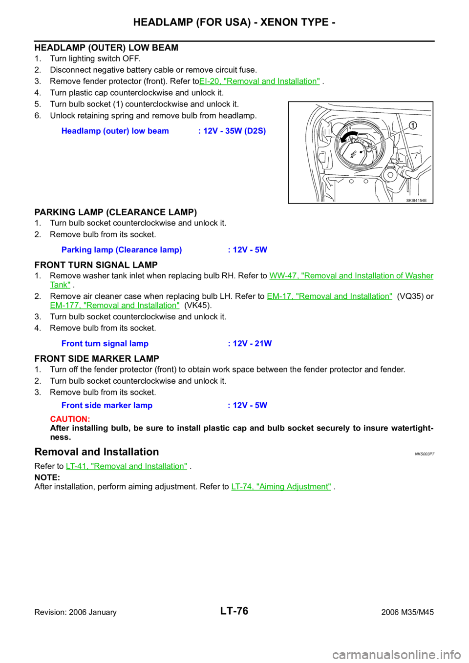
5. Turn bulb socket (1) counterclockwise and unlock it.
6. Unlock retaining spring and remove bulb from headlamp.
PARKING LAMP (CLEARANCE LAMP)
1. Turn bulb socket counterclockwise and unlock it.
2. Remove bulb from its socket.
FRONT TURN SIGNAL LAMP
1. Remove washer tank inlet when replacing bulb RH. Refer to WW-47, "Removal and Installation of Washer
Ta n k" .
2. Remove air cleaner case when replacing bulb LH. Refer to EM-17, "
Removal and Installation" (VQ35) or
EM-177, "
Removal and Installation" (VK45).
3. Turn bulb socket counterclockwise and unlock it.
4. Remove bulb from its socket.
FRONT SIDE MARKER LAMP
1. Turn off the fender protector (front) to obtain work space between the fender protector and fender.
2. Turn bulb socket counterclockwise and unlock it.
3. Remove bulb from its socket.
CAUTION:
After installing bulb, be sure to install plastic cap and bulb socket securely to insure watertight-
ness.
Removal and InstallationNKS003P7
Refer to LT-41, "Removal and Installation" .
NOTE:
After installation, perform aiming adjustment. Refer to LT- 7 4 , "
Aiming Adjustment" . Headlamp (outer) low beam : 12V - 35W (D2S)
SKIB4154E
Parking lamp (Clearance lamp) : 12V - 5W
Front turn signal lamp : 12V - 21W
Front side marker lamp : 12V - 5W
Page 4505 of 5621
LT-78
HEADLAMP (FOR USA) - XENON TYPE -
Revision: 2006 January2006 M35/M45
ASSEMBLY
Note the following, and installation is the reverse order of removal.
CAUTION:
When HID control unit is removed, reinstall it securely and avoid any looseness.
After installing bulb, be sure to install plastic cap and bulb socket securely to insure watertight-
ness HID control unit mounting screw : 3.2 Nꞏm (0.32 kg-m, 28 in-lb)
Page 4551 of 5621
LT-124
AUTO LIGHT SYSTEM
Revision: 2006 January2006 M35/M45
NOTE:
Optical sensor must be securely subjected to work lamp light. If the optical sensor is insufficiently illuminated, the measured value may
not satisfy standard.33 GRCombination
switch output 4ONLighting, turn, wiper
OFF
(Wiper dial position 4)Lighting switch AUTO
Approx. 1.2V
OFF
Approx. 7.0 - 7.5V
38 WIgnition switch
(ON) ON — Battery voltage
39 L CAN
H — — —
40 P CAN
L — — —
42 PBattery power
supplyOFF — Battery voltage
52 B Ground ON — Approx. 0V
55 WBattery power
supplyOFF — Battery voltage
62 VFront door switch
driver side signalOFFFront door switch
driver sideON (open) Approx. 0V
OFF (closed)
Approx. 7.5 - 8.0V
63 R/GRear door switch
LH signalOFF Rear door switch LHON (open) Approx. 0V
OFF (closed)
Approx. 7.5 - 8.0V Te r m i n a l
No.Wire
colorSignal nameMeasuring condition
Reference value
Ignition
switchOperation or condition
PKIB4958J
PKIB4960J
PKIB4960J
PKIB4960J
Page 4558 of 5621

AUTO LIGHT SYSTEM
LT-131
C
D
E
F
G
H
I
J
L
MA
B
LT
Revision: 2006 January2006 M35/M45
Lighting Switch InspectionNKS003QB
1. CHECK LIGHTING SWITCH INPUT SIGNAL
With CONSULT-II
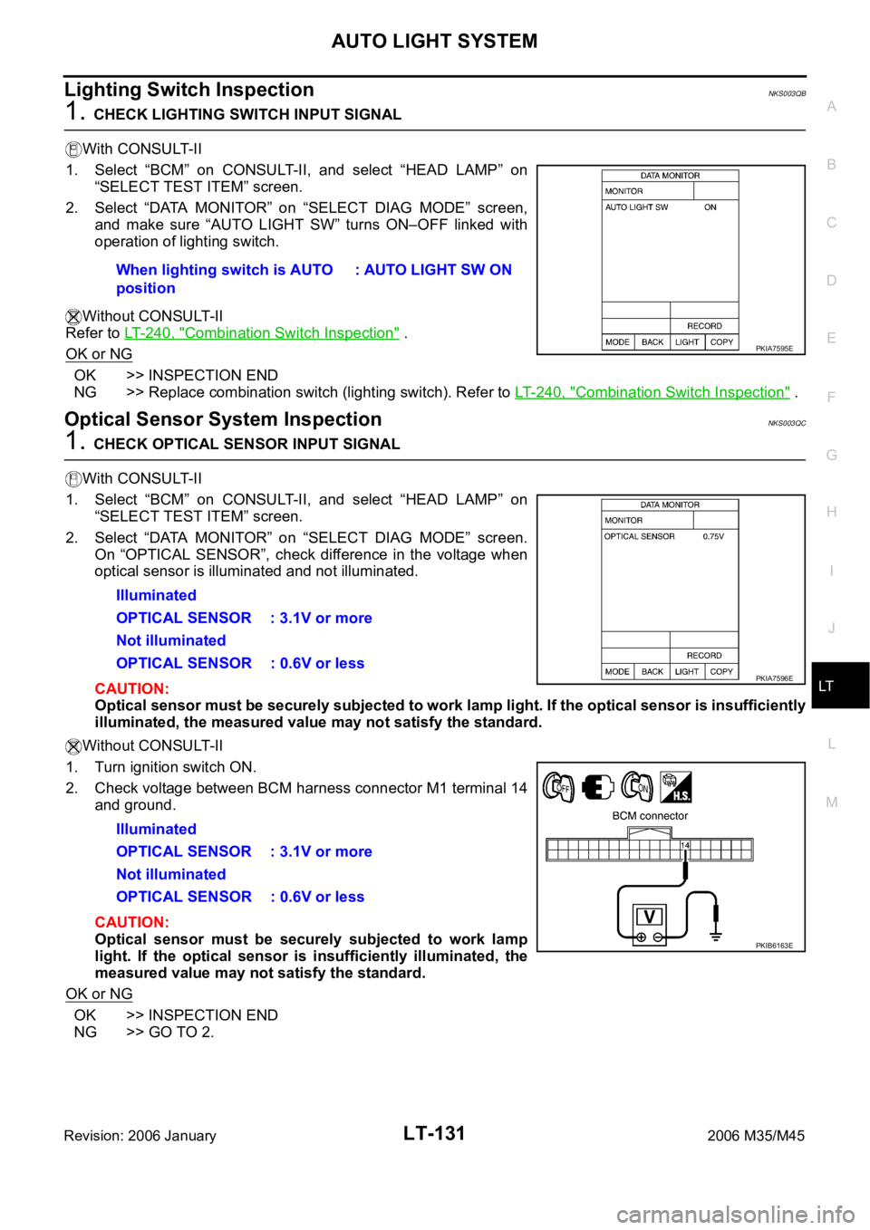
1. Select “BCM” on CONSULT-II, and select “HEAD LAMP” on
“SELECT TEST ITEM” screen.
2. Select “DATA MONITOR” on “SELECT DIAG MODE” screen,
and make sure “AUTO LIGHT SW” turns ON–OFF linked with
operation of lighting switch.
Without CONSULT-II
Refer to LT-240, "
Combination Switch Inspection" .
OK or NG
OK >> INSPECTION END
NG >> Replace combination switch (lighting switch). Refer to LT- 2 4 0 , "
Combination Switch Inspection" .
Optical Sensor System InspectionNKS003QC
1. CHECK OPTICAL SENSOR INPUT SIGNAL
With CONSULT-II
1. Select “BCM” on CONSULT-II, and select “HEAD LAMP” on
“SELECT TEST ITEM” screen.
2. Select “DATA MONITOR” on “SELECT DIAG MODE” screen.
On “OPTICAL SENSOR”, check difference in the voltage when
optical sensor is illuminated and not illuminated.
CAUTION:
Optical sensor must be securely subjected to work lamp light. If the optical sensor is insufficiently
illuminated, the measured value may not satisfy the standard.
Without CONSULT-II
1. Turn ignition switch ON.
2. Check voltage between BCM harness connector M1 terminal 14
and ground.
CAUTION:
Optical sensor must be securely subjected to work lamp
light. If the optical sensor is insufficiently illuminated, the
measured value may not satisfy the standard.
OK or NG
OK >> INSPECTION END
NG >> GO TO 2.When lighting switch is AUTO
position: AUTO LIGHT SW ON
PKIA7595E
Illuminated
OPTICAL SENSOR : 3.1V or more
Not illuminated
OPTICAL SENSOR : 0.6V or less
Illuminated
OPTICAL SENSOR : 3.1V or more
Not illuminated
OPTICAL SENSOR : 0.6V or less
PKIA7596E
PKIB6163E
Page 4579 of 5621

LT-152
ACTIVE AFS
Revision: 2006 January2006 M35/M45
CONSULT-II Function (ADAPTIVE LIGHT)NKS003QM
CONSULT-II can display each diagnostic item using diagnostic test modes shown following.
CONSULT-II BASIC OPERATION
CAUTION:
If CONSULT-II is used with no connection of CONSULT-II CONVERTER, malfunctions might be
detected in self-diagnosis depending on control unit which carry out CAN communication.
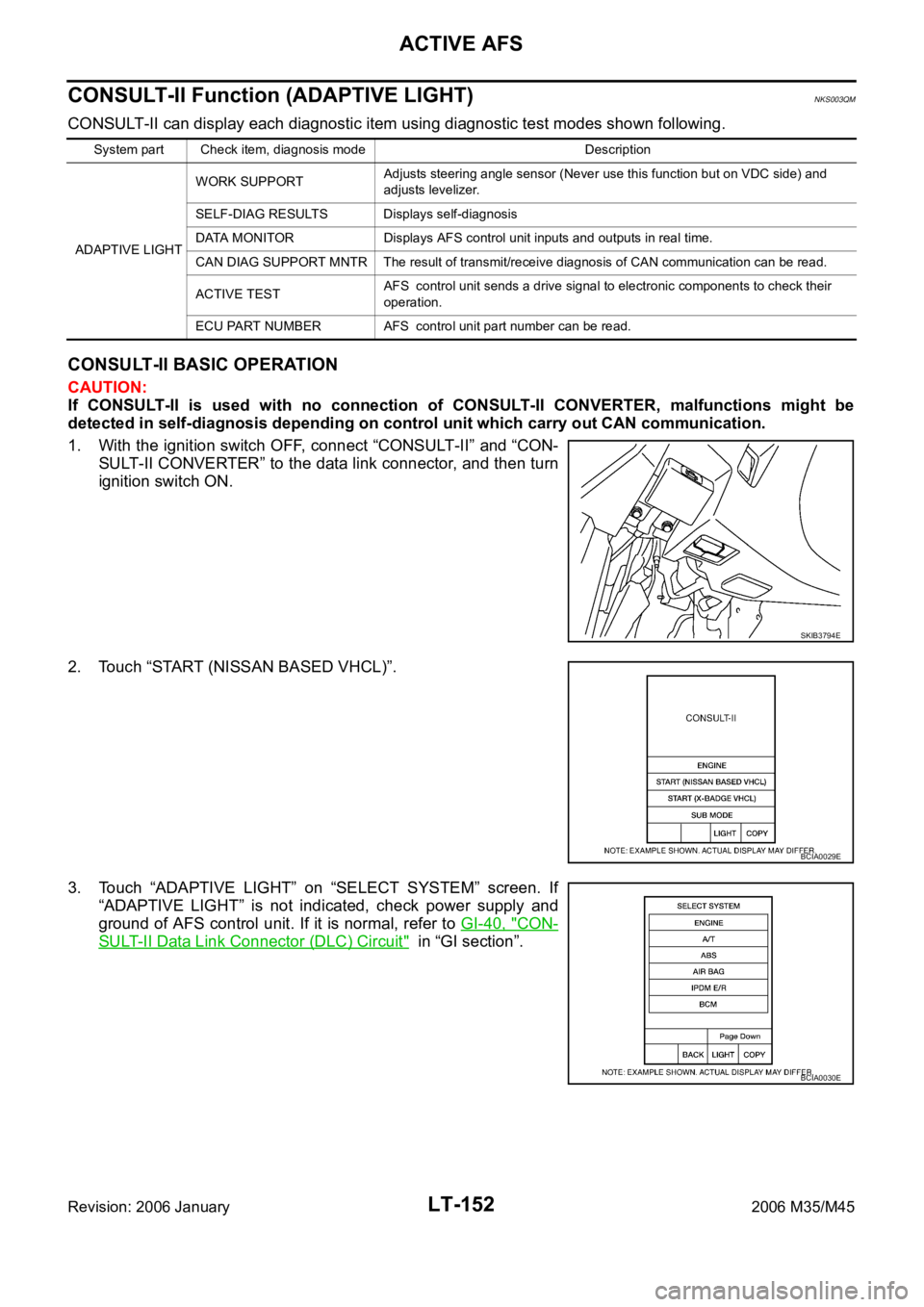
1. With the ignition switch OFF, connect “CONSULT-II” and “CON-
SULT-II CONVERTER” to the data link connector, and then turn
ignition switch ON.
2. Touch “START (NISSAN BASED VHCL)”.
3. Touch “ADAPTIVE LIGHT” on “SELECT SYSTEM” screen. If
“ADAPTIVE LIGHT” is not indicated, check power supply and
ground of AFS control unit. If it is normal, refer to GI-40, "
CON-
SULT-II Data Link Connector (DLC) Circuit" in “GI section”.
System part Check item, diagnosis mode Description
ADAPTIVE LIGHTWORK SUPPORTAdjusts steering angle sensor (Never use this function but on VDC side) and
adjusts levelizer.
SELF-DIAG RESULTS Displays self-diagnosis
DATA MONITOR Displays AFS control unit inputs and outputs in real time.
CAN DIAG SUPPORT MNTR The result of transmit/receive diagnosis of CAN communication can be read.
ACTIVE TESTAFS control unit sends a drive signal to electronic components to check their
operation.
ECU PART NUMBER AFS control unit part number can be read.
SKIB3794E
BCIA0029E
BCIA0030E
Page 4584 of 5621
![INFINITI M35 2006 Factory Service Manual ACTIVE AFS
LT-157
C
D
E
F
G
H
I
J
L
MA
B
LT
Revision: 2006 January2006 M35/M45
CAUTION:
If DTC relating to CAN communication [U1000] and other components are displayed at the same
time, INFINITI M35 2006 Factory Service Manual ACTIVE AFS
LT-157
C
D
E
F
G
H
I
J
L
MA
B
LT
Revision: 2006 January2006 M35/M45
CAUTION:
If DTC relating to CAN communication [U1000] and other components are displayed at the same
time,](/manual-img/42/57023/w960_57023-4583.png)
ACTIVE AFS
LT-157
C
D
E
F
G
H
I
J
L
MA
B
LT
Revision: 2006 January2006 M35/M45
CAUTION:
If DTC relating to CAN communication [U1000] and other components are displayed at the same
time, diagnose CAN communication first.
Make sure of the normal operation after the parts (except AFS control unit) replacement according
to the self-diagnosis results. Delete the malfunction history.
Display Results
0: There is malfunction now.
1 – 39: Displays when it is normal at present and finds malfunction in the past. It increases in order
of 0
12...3839 after returning to the normal condition whenever IGN OFFON. If it is over 39,
it is fixed to 39 until the self-diagnostic results are erased. It returns to 0 when malfunction is
detected again in the process.
ECU CIRC
[B2521]Any of several statuses below
Short circuit exists for 2 seconds or longer on power supply
(approx. 12 V) or ground of swivel position sensor (RH) power
supply (AFS control unit terminal 4).
Short circuit exists for 2 seconds or longer on power supply
(approx. 12 V) of swivel position sensor (RH) signal (AFS con-
trol unit terminal 9).
Short circuit exists for 2 seconds or longer on power supply
(approx. 12 V) or ground of swivel position sensor (LH) power
supply (AFS control unit terminal 24).
Short circuit exists for 2 seconds or longer on power supply
(approx. 12 V) of swivel position sensor (LH) signal (AFS con-
trol unit terminal 29).
Short circuit exists for 2 seconds or longer on power supply
(approx. 12 V) or ground of height sensor power supply (AFS
control unit terminal 6).
Short circuit exists for 2 seconds or longer on power supply
(approx. 12 V) of height sensor signal (AFS control unit termi-
nal 28).
AFS control unit (RAM/ROM) malfunctions.1. Stop the swivel motor RH and
LH when the malfunction
occurred.
2. Stop aiming motors when the
malfunction occurred.
3. Flash at intervals of approx. 1
second when keeping error state
for 2 seconds or longer.
4. Turn ignition switch OFF.LT-178, "
DTC
B2521 ECU
CIRC"
ECM SIG
[B2522]Cannot receive engine speed signal.1. Back to the initial position.
2. Stop when the malfunction
occurred.
3. Flash at intervals of approx. 1
second when keeping error state
for 2 seconds or longer.
4. Turn ignition switch OFF.EC-137,
"SELF-DIAG
RESULTS
MODE" in EC
section.
If above sys-
tem is normal,
replace AFS
control unit.
AFS SIG
[B2523]Cannot transmit AFS off indicator signal.1. Back to the initial position.
2. Normal operation
3. Flashes at intervals of approx. 1
second when keeping error state
for 2 seconds or longer.
4. Turn ignition switch OFF.Replace
AFS control
unit LT-191
Details of
error
indication
detected by
CONSULT-
IIConditions of error detectionFail-safe
1. Swivel operation
2. Auto aiming operation
3. AFS OFF indicator operation
4. CancellationReference
Page 4591 of 5621

LT-164
ACTIVE AFS
Revision: 2006 January2006 M35/M45
7. CHECK SWIVEL POSITION SENSOR GROUND CIRCUIT
1. Turn ignition switch OFF.
2. Disconnect AFS control unit connector and front combination lamp RH connector.
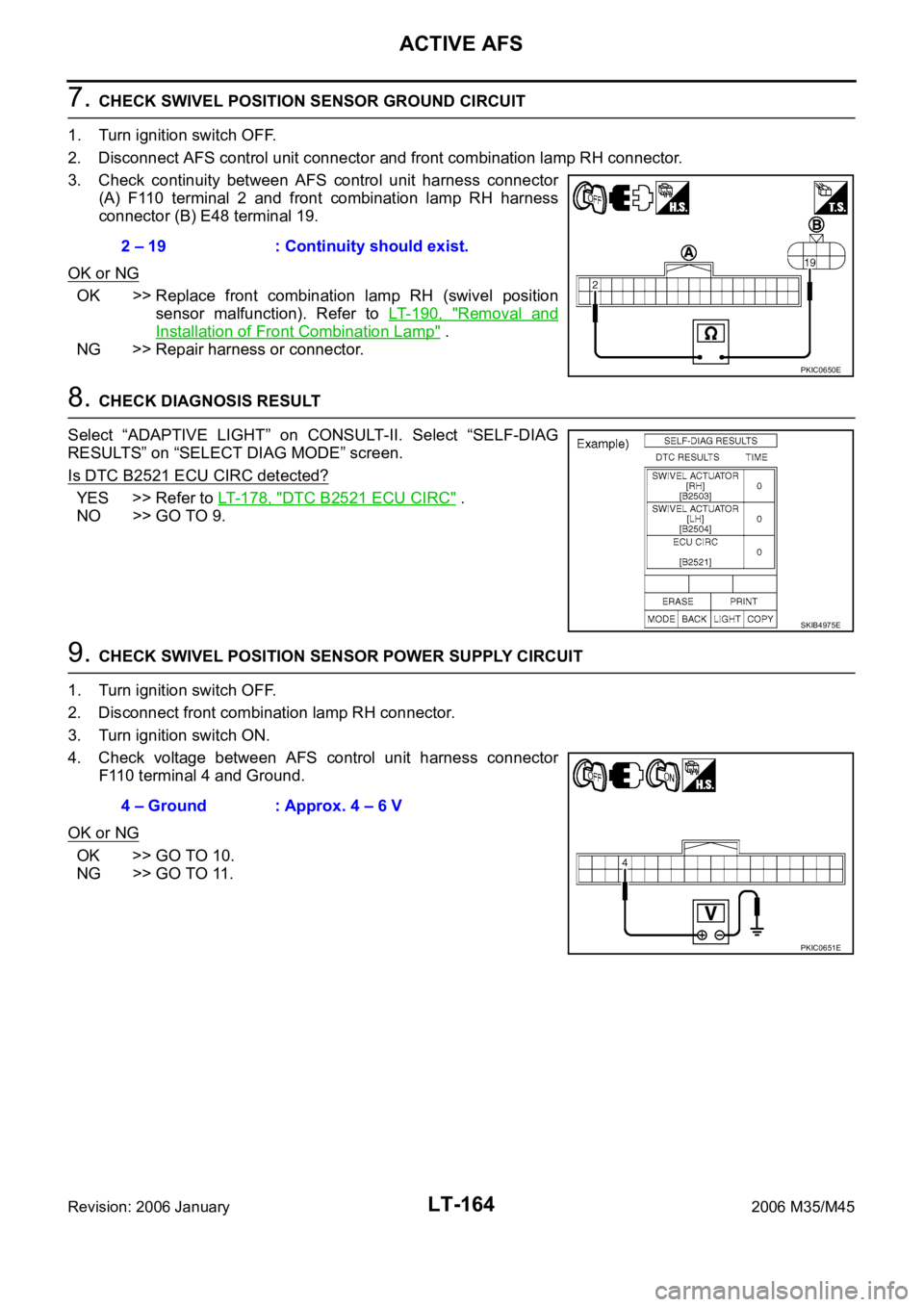
3. Check continuity between AFS control unit harness connector
(A) F110 terminal 2 and front combination lamp RH harness
connector (B) E48 terminal 19.
OK or NG
OK >> Replace front combination lamp RH (swivel position
sensor malfunction). Refer to LT- 1 9 0 , "
Removal and
Installation of Front Combination Lamp" .
NG >> Repair harness or connector.
8. CHECK DIAGNOSIS RESULT
Select “ADAPTIVE LIGHT” on CONSULT-II. Select “SELF-DIAG
RESULTS” on “SELECT DIAG MODE” screen.
Is DTC B2521 ECU CIRC detected?
YES >> Refer to LT- 1 7 8 , "DTC B2521 ECU CIRC" .
NO >> GO TO 9.
9. CHECK SWIVEL POSITION SENSOR POWER SUPPLY CIRCUIT
1. Turn ignition switch OFF.
2. Disconnect front combination lamp RH connector.
3. Turn ignition switch ON.
4. Check voltage between AFS control unit harness connector
F110 terminal 4 and Ground.
OK or NG
OK >> GO TO 10.
NG >> GO TO 11.2 – 19 : Continuity should exist.
PKIC0650E
SKIB4975E
4 – Ground : Approx. 4 – 6 V
PKIC0651E