2006 INFINITI M35 ECU
[x] Cancel search: ECUPage 3391 of 5621

FFD-14
FRONT FINAL DRIVE ASSEMBLY
Revision: 2006 January2006 M35/M45
INSTALLATION
Note the following, and installation is in the reverse order of removal.
Refer to FFD-13, "COMPONENTS" about each tightening torque.
When installing the side shaft, apply multi-purpose grease to contact surface of side shaft and side shaft
oil seal.
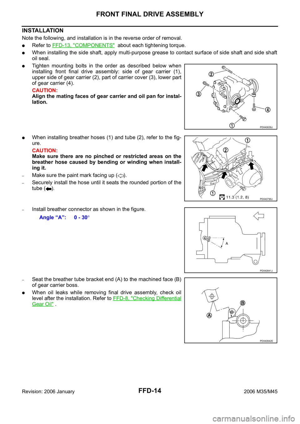
Tighten mounting bolts in the order as described below when
installing front final drive assembly: side of gear carrier (1),
upper side of gear carrier (2), part of carrier cover (3), lower part
of gear carrier (4).
CAUTION:
Align the mating faces of gear carrier and oil pan for instal-
lation.
When installing breather hoses (1) and tube (2), refer to the fig-
ure.
CAUTION:
Make sure there are no pinched or restricted areas on the
breather hose caused by bending or winding when install-
ing it.
–Make sure the paint mark facing up ( ).
–Securely install the hose until it seats the rounded portion of the
tube ( ).
–Install breather connector as shown in the figure.
–Seat the breather tube bracket end (A) to the machined face (B)
of gear carrier boss.
When oil leaks while removing final drive assembly, check oil
level after the installation. Refer to FFD-8, "
Checking Differential
Gear Oil" .
PDIA0839J
PDIA0790J
Angle “A”: 0 - 30
PDIA0841J
PDIA0842E
Page 3416 of 5621

FUEL SYSTEM
FL-3
C
D
E
F
G
H
I
J
K
L
MA
FL
Revision: 2006 January2006 M35/M45
FUEL SYSTEMPFP:17503
Checking Fuel LinesNBS005R8
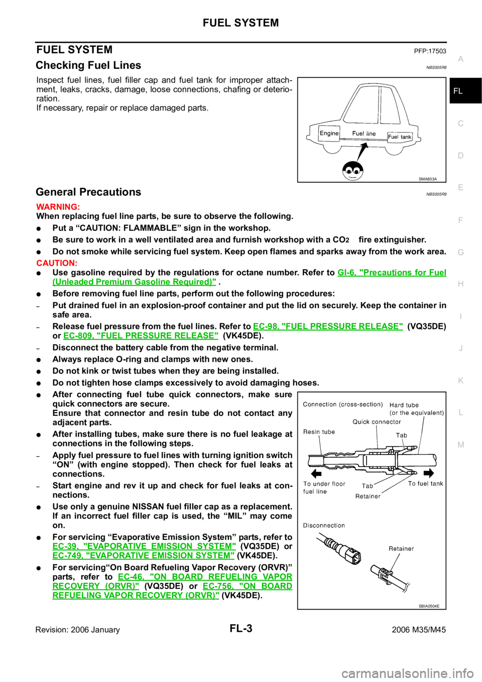
Inspect fuel lines, fuel filler cap and fuel tank for improper attach-
ment, leaks, cracks, damage, loose connections, chafing or deterio-
ration.
If necessary, repair or replace damaged parts.
General PrecautionsNBS005R9
WAR NING :
When replacing fuel line parts, be sure to observe the following.
Put a “CAUTION: FLAMMABLE” sign in the workshop.
Be sure to work in a well ventilated area and furnish workshop with a CO2 fire extinguisher.
Do not smoke while servicing fuel system. Keep open flames and sparks away from the work area.
CAUTION:
Use gasoline required by the regulations for octane number. Refer to GI-6, "Precautions for Fuel
(Unleaded Premium Gasoline Required)" .
Before removing fuel line parts, perform out the following procedures:
–Put drained fuel in an explosion-proof container and put the lid on securely. Keep the container in
safe area.
–Release fuel pressure from the fuel lines. Refer to EC-98, "FUEL PRESSURE RELEASE" (VQ35DE)
or EC-809, "
FUEL PRESSURE RELEASE" (VK45DE).
–Disconnect the battery cable from the negative terminal.
Always replace O-ring and clamps with new ones.
Do not kink or twist tubes when they are being installed.
Do not tighten hose clamps excessively to avoid damaging hoses.
After connecting fuel tube quick connectors, make sure
quick connectors are secure.
Ensure that connector and resin tube do not contact any
adjacent parts.
After installing tubes, make sure there is no fuel leakage at
connections in the following steps.
–Apply fuel pressure to fuel lines with turning ignition switch
“ON” (with engine stopped). Then check for fuel leaks at
connections.
–Start engine and rev it up and check for fuel leaks at con-
nections.
Use only a genuine NISSAN fuel filler cap as a replacement.
If an incorrect fuel filler cap is used, the “MIL” may come
on.
For servicing “Evaporative Emission System” parts, refer to
EC-39, "
EVAPORATIVE EMISSION SYSTEM" (VQ35DE) or
EC-749, "
EVAPORATIVE EMISSION SYSTEM" (VK45DE).
For servicing“On Board Refueling Vapor Recovery (ORVR)”
parts, refer to EC-46, "
ON BOARD REFUELING VAPOR
RECOVERY (ORVR)" (VQ35DE) or EC-756, "ON BOARD
REFUELING VAPOR RECOVERY (ORVR)" (VK45DE).
SMA803A
SBIA0504E
Page 3420 of 5621

FUEL LEVEL SENSOR UNIT, FUEL FILTER AND FUEL PUMP ASSEMBLY
FL-7
C
D
E
F
G
H
I
J
K
L
MA
FL
Revision: 2006 January2006 M35/M45
Fuel hose
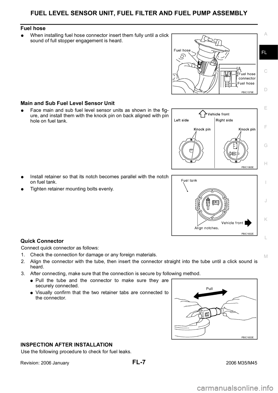
When installing fuel hose connector insert them fully until a click
sound of full stopper engagement is heard.
Main and Sub Fuel Level Sensor Unit
Face main and sub fuel level sensor units as shown in the fig-
ure, and install them with the knock pin on back aligned with pin
hole on fuel tank.
Install retainer so that its notch becomes parallel with the notch
on fuel tank.
Tighten retainer mounting bolts evenly.
Quick Connector
Connect quick connector as follows:
1. Check the connection for damage or any foreign materials.
2. Align the connector with the tube, then insert the connector straight into the tube until a click sound is
heard.
3. After connecting, make sure that the connection is secure by following method.
Pull the tube and the connector to make sure they are
securely connected.
Visually confirm that the two retainer tabs are connected to
the connector.
INSPECTION AFTER INSTALLATION
Use the following procedure to check for fuel leaks.
PBIC1579E
PBIC1065E
PBIC1652E
PBIC1653E
Page 3422 of 5621

FUEL LEVEL SENSOR UNIT, FUEL FILTER AND FUEL PUMP ASSEMBLY
FL-9
C
D
E
F
G
H
I
J
K
L
MA
FL
Revision: 2006 January2006 M35/M45
ASSEMBLY
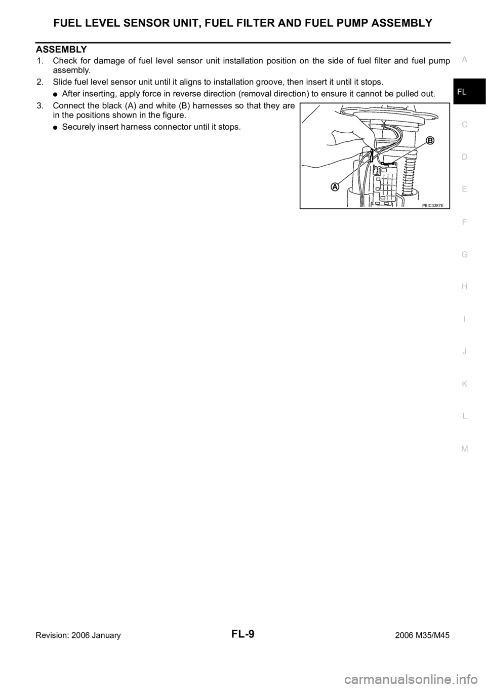
1. Check for damage of fuel level sensor unit installation position on the side of fuel filter and fuel pump
assembly.
2. Slide fuel level sensor unit until it aligns to installation groove, then insert it until it stops.
After inserting, apply force in reverse direction (removal direction) to ensure it cannot be pulled out.
3. Connect the black (A) and white (B) harnesses so that they are
in the positions shown in the figure.
Securely insert harness connector until it stops.
PBIC3387E
Page 3438 of 5621
![INFINITI M35 2006 Factory Service Manual COIL SPRING AND SHOCK ABSORBER
FSU-11
[2WD]
C
D
F
G
H
I
J
K
L
MA
B
FSU
Revision: 2006 January2006 M35/M45
COIL SPRING AND SHOCK ABSORBERPFP:55302
Removal and InstallationNES000IE
REMOVAL
1. Remove tir INFINITI M35 2006 Factory Service Manual COIL SPRING AND SHOCK ABSORBER
FSU-11
[2WD]
C
D
F
G
H
I
J
K
L
MA
B
FSU
Revision: 2006 January2006 M35/M45
COIL SPRING AND SHOCK ABSORBERPFP:55302
Removal and InstallationNES000IE
REMOVAL
1. Remove tir](/manual-img/42/57023/w960_57023-3437.png)
COIL SPRING AND SHOCK ABSORBER
FSU-11
[2WD]
C
D
F
G
H
I
J
K
L
MA
B
FSU
Revision: 2006 January2006 M35/M45
COIL SPRING AND SHOCK ABSORBERPFP:55302
Removal and InstallationNES000IE
REMOVAL
1. Remove tires from vehicle with a power tool.
2. Remove harness of wheel sensor from shock absorber. Refer to BRC-57, "
WHEEL SENSOR" .
CAUTION:
Do not pull on wheel sensor harness.
3. Remove brake hose bracket. Refer to BR-12, "
BRAKE TUBE AND HOSE" .
4. Remove the mounting nut on the upper side of stabilizer connecting rod with a power tool, and then
remove stabilizer connecting rod from transverse link.
5. Remove mounting nut and bolt on the lower side of shock absorber with a power tool, and then remove
shock absorber from transverse link.
6. Remove cotter pin of transverse link and steering knuckle, and then loosen nut.
7. Remove transverse link from steering knuckle so as not to damage ball joint boot using the ball joint
remover (suitable tool).
CAUTION:
Temporarily tighten the nut to prevent damage to threads and to prevent ball joint remover (suit-
able tool) from suddenly coming off.
8. Remove the mounting nuts of shock absorber mounting bracket, then remove shock absorber from vehi-
cle.
INSTALLATION
Installation is the reverse order of removal. For tightening torque, refer to FSU-8, "Components" .
Perform final tightening of bolt and nut at the shock absorber lower side (rubber bushing), under unladen
conditions with tires on level ground. Check wheel alignment. Refer to FSU-6, "
Wheel Alignment Inspec-
tion" .
Adjust neutral position of steering angle sensor after checking wheel alignment. Refer to BRC-6, "Adjust-
ment of Steering Angle Sensor Neutral Position" .
Check wheel sensor harness for proper connection. Refer to BRC-57, "WHEEL SENSOR" .
Disassembly and AssemblyNES000IF
DISASSEMBLY
CAUTION:
Do not damage shock absorber piston rod when removing components from shock absorber.
1. Install strut attachment [SST] to shock absorber and secure it in
a vise.
CAUTION:
When installing the strut attachment to shock absorber,
wrap a shop cloth around strut to protect it from damage.
SEIA0296E
Page 3439 of 5621
![INFINITI M35 2006 Factory Service Manual FSU-12
[2WD]
COIL SPRING AND SHOCK ABSORBER
Revision: 2006 January2006 M35/M45
2. Using a spring compressor (commercial service tool), compress
coil spring between rubber seat and spring lower seat (o INFINITI M35 2006 Factory Service Manual FSU-12
[2WD]
COIL SPRING AND SHOCK ABSORBER
Revision: 2006 January2006 M35/M45
2. Using a spring compressor (commercial service tool), compress
coil spring between rubber seat and spring lower seat (o](/manual-img/42/57023/w960_57023-3438.png)
FSU-12
[2WD]
COIL SPRING AND SHOCK ABSORBER
Revision: 2006 January2006 M35/M45
2. Using a spring compressor (commercial service tool), compress
coil spring between rubber seat and spring lower seat (on shock
absorber) until coil spring with a spring compressor is free.
CAUTION:
Be sure a spring compressor is securely attached coil
spring. Compress coil spring
3. Make sure coil spring with a spring compressor between rubber
seat and spring lower seat (shock absorber) is free and then
remove piston rod lock nut while securing the piston rod tip so
that piston rod does not turn.
4. Remove shock absorber mounting bracket, rubber seat, bound
bumper from shock absorber.
5. Remove coil spring with a spring compressor, and then gradually release a spring compressor.
CAUTION:
Loosen while making sure coil spring attachment position does not move.
6. Remove the strut attachment from shock absorber.
INSPECTION AFTER DISASSEMBLY
Shock Absorber Inspection
Check the following:
Shock absorber for deformation, cracks or damage, and replace it if a malfunction is detected.
Piston rod for damage, uneven wear or distortion, and replace it if a malfunction is detected.
For oil leakage, and replace it if a malfunction is detected.
Shock Absorber Mounting Bracket and Rubber Parts Inspection
Check shock absorber mounting bracket for cracks and rubber parts for wear. Replace it if a malfunction is
detected.
Coil Spring Inspection
Check coil spring for cracks, wear or damage, and replace it if a malfunction is detected.
ASSEMBLY
CAUTION:
Do not damage shock absorber piston rod when installing components to shock absorber.
1. Install strut attachment [SST] to shock absorber and secure it in
a vise.
CAUTION:
When installing the strut attachment to shock absorber,
wrap a shop cloth around strut to protect it from damage.
2. Compress coil spring using a spring compressor (commercial
service tool), and install it onto shock absorber.
SEIA0297E
SEIA0296E
SEIA0297E
Page 3440 of 5621
![INFINITI M35 2006 Factory Service Manual COIL SPRING AND SHOCK ABSORBER
FSU-13
[2WD]
C
D
F
G
H
I
J
K
L
MA
B
FSU
Revision: 2006 January2006 M35/M45
CAUTION:
Install coil spring as shown in the figure with large diame-
ter side [100 mm (3.94 i INFINITI M35 2006 Factory Service Manual COIL SPRING AND SHOCK ABSORBER
FSU-13
[2WD]
C
D
F
G
H
I
J
K
L
MA
B
FSU
Revision: 2006 January2006 M35/M45
CAUTION:
Install coil spring as shown in the figure with large diame-
ter side [100 mm (3.94 i](/manual-img/42/57023/w960_57023-3439.png)
COIL SPRING AND SHOCK ABSORBER
FSU-13
[2WD]
C
D
F
G
H
I
J
K
L
MA
B
FSU
Revision: 2006 January2006 M35/M45
CAUTION:
Install coil spring as shown in the figure with large diame-
ter side [100 mm (3.94 in)] up and small diameter side [90
mm (3.54 in)] down. (Distinction marks are 4.75 and 5.75
turn from the lower side end.)
Be sure a spring compress or is securely attached to coil
spring. Compress coil spring.
3. Apply soapy water to bound bumper. Insert bound bumper into
shock absorber mounting bracket, and then install it to shock
absorber together with rubber seat.
CAUTION:
Do not use machine oil.
Install shock absorber mounting bracket as shown in the fig-
ure.
CAUTION:
Coil spring is securely seated in spring mounting groove
of rubber seat.
The bottom part of spring should be at the position of A
point of spring seat.
4. Secure piston rod tip so that piston rod does not turn, then
tighten piston rod lock nut with specified torque.
5. Gradually release a spring compressor, and remove coil spring.
CAUTION:
Loosen while making sure coil spring attachment position
does not move.
6. Remove the strut attachment from shock absorber.
SEIA0661E
SEIA0662E
Page 3455 of 5621
![INFINITI M35 2006 Factory Service Manual FSU-28
[AWD]
COIL SPRING AND SHOCK ABSORBER
Revision: 2006 January2006 M35/M45
COIL SPRING AND SHOCK ABSORBERPFP:55302
Removal and InstallationNES000IU
REMOVAL
1. Remove tires from vehicle with a powe INFINITI M35 2006 Factory Service Manual FSU-28
[AWD]
COIL SPRING AND SHOCK ABSORBER
Revision: 2006 January2006 M35/M45
COIL SPRING AND SHOCK ABSORBERPFP:55302
Removal and InstallationNES000IU
REMOVAL
1. Remove tires from vehicle with a powe](/manual-img/42/57023/w960_57023-3454.png)
FSU-28
[AWD]
COIL SPRING AND SHOCK ABSORBER
Revision: 2006 January2006 M35/M45
COIL SPRING AND SHOCK ABSORBERPFP:55302
Removal and InstallationNES000IU
REMOVAL
1. Remove tires from vehicle with a power tool.
2. Remove harness of wheel sensor from shock absorber. Refer to BRC-57, "
WHEEL SENSOR" .
CAUTION:
Do not pull on wheel sensor harness.
3. Remove brake hose bracket. Refer to BR-12, "
BRAKE TUBE AND HOSE" .
4. Remove the mounting nut on the upper side of stabilizer connecting rod with a power tool, and then
remove stabilizer connecting rod from transverse link.
5. Remove mounting nut and bolt on the lower side of shock absorber arm with a power tool, and then
remove shock absorber arm from transverse link.
6. Remove cotter pin of transverse link and steering knuckle, and then loosen nut.
7. Remove transverse link from steering knuckle so as not to damage ball joint boot using the ball joint
remover (suitable tool).
CAUTION:
Temporarily tighten the nut to prevent damage to threads and to prevent ball joint remover (suit-
able tool) from suddenly coming off.
8. Remove the mounting bolt on the upper side of shock absorber arm with a power tool, and then remove
shock absorber arm from shock absorber.
9. Remove the mounting nuts of shock absorber mounting bracket, then remove shock absorber from vehi-
cle.
INSTALLATION
Installation is the reverse order of removal. For tightening torque, refer to FSU-25, "Components" .
Perform final tightening of bolt and nut at the shock absorber arm lower side (rubber bushing) under
unladen conditions with tires on level ground. Check wheel alignment. Refer to FSU-23, "
Wheel Align-
ment Inspection" .
Adjust neutral position of steering angle sensor after checking wheel alignment. Refer to BRC-6, "Adjust-
ment of Steering Angle Sensor Neutral Position" .
Check wheel sensor harness for proper connection. Refer to BRC-57, "WHEEL SENSOR" .
Disassembly and AssemblyNES000IV
DISASSEMBLY
CAUTION:
Do not damage shock absorber piston rod when removing components from shock absorber.
1. Install strut attachment [SST] to shock absorber and secure it in
a vise.
CAUTION:
When installing the strut attachment to shock absorber,
wrap a shop cloth around strut to protect it from damage.
SEIA0296E