2006 INFINITI M35 fuel pump
[x] Cancel search: fuel pumpPage 1440 of 5621
COMBINATION METERS
DI-7
C
D
E
F
G
H
I
J
L
MA
B
DI
Revision: 2006 January2006 M35/M45
FUEL GAUGE
The fuel gauge indicates the approximate fuel level in the fuel tank.
The fuel gauge is regulated by a variable ground signal supplied
from unified meter and A/C amp. terminal 58
through the fuel level sensor unit and fuel pump (main) terminals 5 and 2, and
through the fuel level sensor unit (sub) terminals 2 and 1
to unified meter and A/C amp. terminal 42.
Unified meter and A/C amp. provides a fuel level signal to combination meter for fuel gauge with communica-
tion line between unified meter and A/C amp. and combination meter.
ODO/TRIP METER
ABS actuator and electric unit (control unit) converses a pulse signal from wheel sensor to vehicle speed
signal, and transmits vehicle speed signal to unified meter and A/C amp. with CAN communication.
Unified meter and A/C amp. converses vehicle speed signal to 8 pulse signal, and transmits to combina-
tion meter.
Combination meter processes the 8 pulse signal and the memory signals from the meter memory circuit.
Then the mileage is displayed.
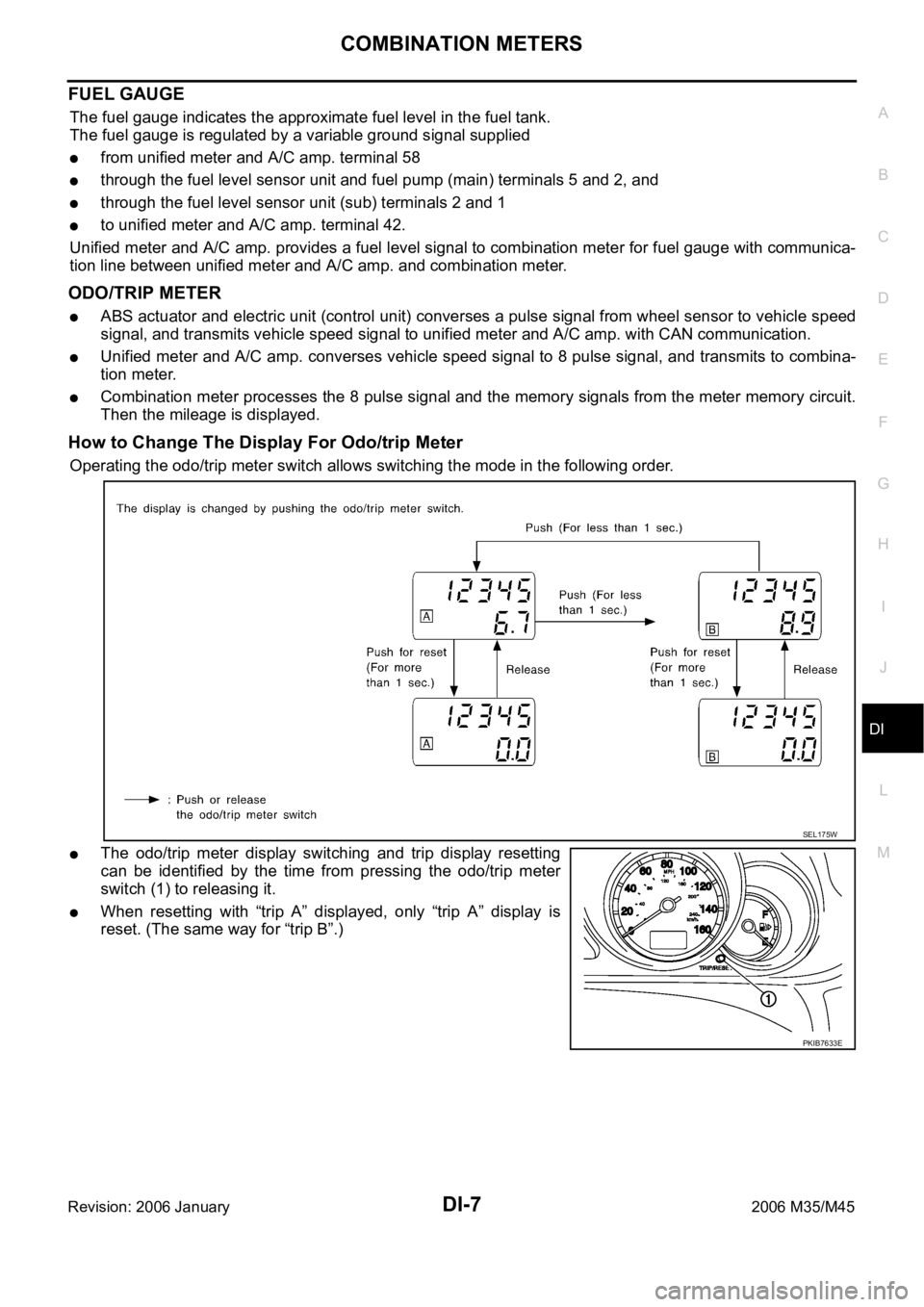
How to Change The Display For Odo/trip Meter
Operating the odo/trip meter switch allows switching the mode in the following order.
The odo/trip meter display switching and trip display resetting
can be identified by the time from pressing the odo/trip meter
switch (1) to releasing it.
When resetting with “trip A” displayed, only “trip A” display is
reset. (The same way for “trip B”.)
SEL175W
PKIB7633E
Page 1457 of 5621
DI-24
COMBINATION METERS
Revision: 2006 January2006 M35/M45
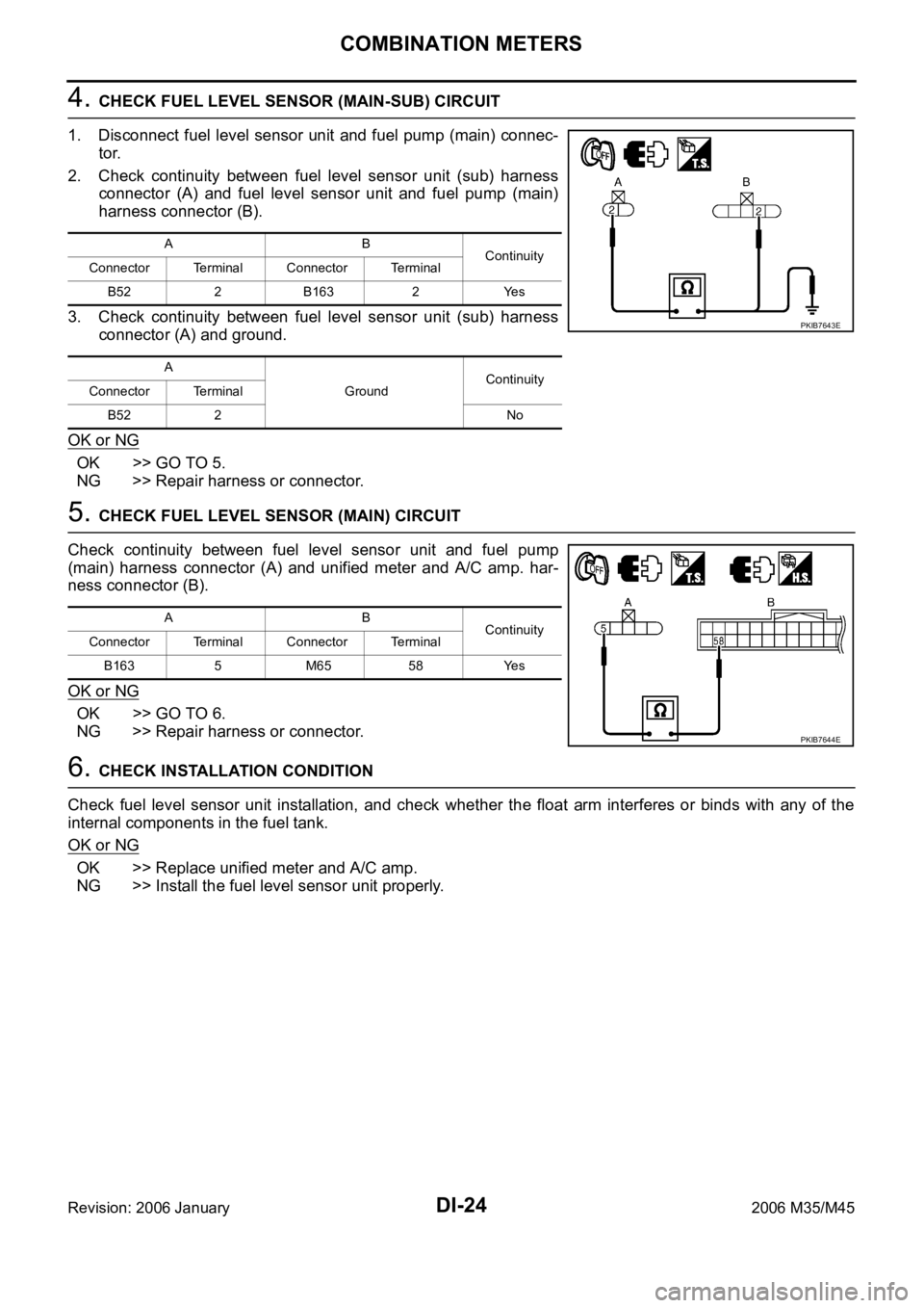
4. CHECK FUEL LEVEL SENSOR (MAIN-SUB) CIRCUIT
1. Disconnect fuel level sensor unit and fuel pump (main) connec-
tor.
2. Check continuity between fuel level sensor unit (sub) harness
connector (A) and fuel level sensor unit and fuel pump (main)
harness connector (B).
3. Check continuity between fuel level sensor unit (sub) harness
connector (A) and ground.
OK or NG
OK >> GO TO 5.
NG >> Repair harness or connector.
5. CHECK FUEL LEVEL SENSOR (MAIN) CIRCUIT
Check continuity between fuel level sensor unit and fuel pump
(main) harness connector (A) and unified meter and A/C amp. har-
ness connector (B).
OK or NG
OK >> GO TO 6.
NG >> Repair harness or connector.
6. CHECK INSTALLATION CONDITION
Check fuel level sensor unit installation, and check whether the float arm interferes or binds with any of the
internal components in the fuel tank.
OK or NG
OK >> Replace unified meter and A/C amp.
NG >> Install the fuel level sensor unit properly.
AB
Continuity
Connector Terminal Connector Terminal
B52 2 B163 2 Yes
A
GroundContinuity
Connector Terminal
B52 2 No
PKIB7643E
AB
Continuity
Connector Terminal Connector Terminal
B1635 M6558Yes
PKIB7644E
Page 1459 of 5621
DI-26
COMBINATION METERS
Revision: 2006 January2006 M35/M45
Electrical Components InspectionNKS003UD
CHECK FUEL LEVEL SENSOR UNIT
For removal, refer to FL-4, "FUEL LEVEL SENSOR UNIT, FUEL FILTER AND FUEL PUMP ASSEMBLY" .
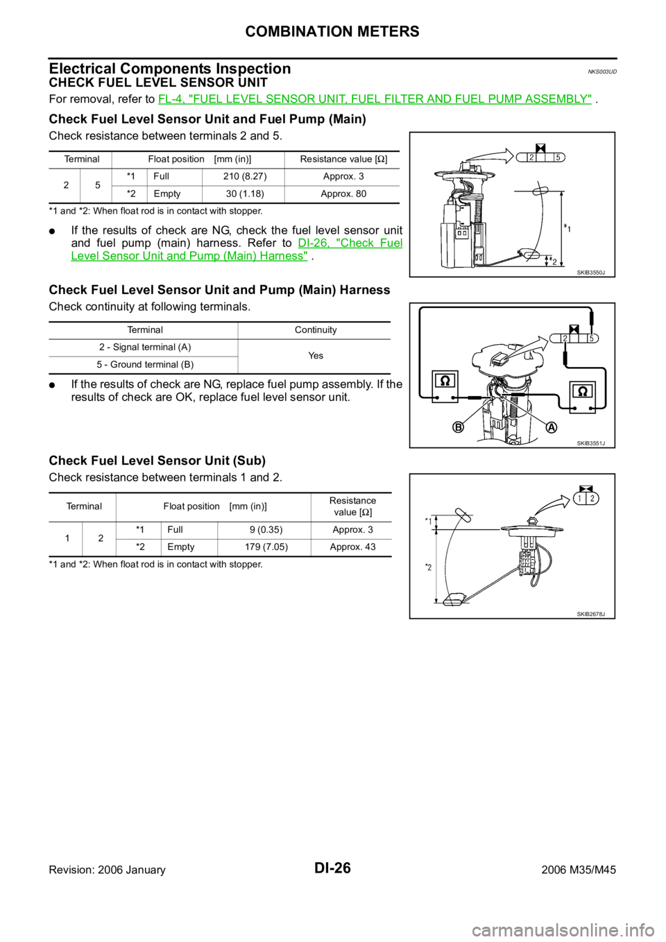
Check Fuel Level Sensor Unit and Fuel Pump (Main)
Check resistance between terminals 2 and 5.
*1 and *2: When float rod is in contact with stopper.
If the results of check are NG, check the fuel level sensor unit
and fuel pump (main) harness. Refer to DI-26, "
Check Fuel
Level Sensor Unit and Pump (Main) Harness" .
Check Fuel Level Sensor Unit and Pump (Main) Harness
Check continuity at following terminals.
If the results of check are NG, replace fuel pump assembly. If the
results of check are OK, replace fuel level sensor unit.
Check Fuel Level Sensor Unit (Sub)
Check resistance between terminals 1 and 2.
*1 and *2: When float rod is in contact with stopper.Terminal Float position [mm (in)] Resistance value [
]
25*1 Full 210 (8.27) Approx. 3
*2 Empty 30 (1.18) Approx. 80
SKIB3550J
Terminal Continuity
2 - Signal terminal (A)
Ye s
5 - Ground terminal (B)
SKIB3551J
Terminal Float position [mm (in)]Resistance
value []
12*1 Full 9 (0.35) Approx. 3
*2 Empty 179 (7.05) Approx. 43
SKIB2678J
Page 1548 of 5621
EC-5
C
D
E
F
G
H
I
J
K
L
M
ECA
Revision: 2006 January2006 M35/M45 DTC Confirmation Procedure ...............................451
Wiring Diagram ....................................................452
Diagnostic Procedure ...........................................453
Component Inspection .........................................457
DTC P0455 EVAP CONTROL SYSTEM ................458
On Board Diagnosis Logic ...................................458
DTC Confirmation Procedure ...............................459
Diagnostic Procedure ...........................................460
DTC P0456 EVAP CONTROL SYSTEM ................466
On Board Diagnosis Logic ...................................466
DTC Confirmation Procedure ...............................467
Overall Function Check ........................................468
Diagnostic Procedure ...........................................469
DTC P0460 FUEL LEVEL SENSOR ......................475
Component Description ........................................475
On Board Diagnosis Logic ...................................475
DTC Confirmation Procedure ...............................475
Diagnostic Procedure ...........................................476
Removal and Installation ......................................476
DTC P0461 FUEL LEVEL SENSOR ......................477
Component Description ........................................477
On Board Diagnosis Logic ...................................477
Overall Function Check ........................................477
Diagnostic Procedure ...........................................478
Removal and Installation ......................................478
DTC P0462, P0463 FUEL LEVEL SENSOR CIR-
CUIT ........................................................................479
Component Description ........................................479
On Board Diagnosis Logic ...................................479
DTC Confirmation Procedure ...............................479
Diagnostic Procedure ...........................................480
Removal and Installation ......................................480
DTC P0500 VSS .....................................................481
Description ...........................................................481
On Board Diagnosis Logic ...................................481
DTC Confirmation Procedure ...............................481
Overall Function Check ........................................482
Diagnostic Procedure ...........................................482
DTC P0506 ISC SYSTEM .......................................483
Description ...........................................................483
On Board Diagnosis Logic ...................................483
DTC Confirmation Procedure ...............................483
Diagnostic Procedure ...........................................484
DTC P0507 ISC SYSTEM .......................................485
Description ...........................................................485
On Board Diagnosis Logic ...................................485
DTC Confirmation Procedure ..............................
.485
Diagnostic Procedure ...........................................486
DTC P0550 PSP SENSOR .....................................487
Component Description ........................................487
CONSULT-II Reference Value in Data Monitor Mode
.487
On Board Diagnosis Logic ...................................487
DTC Confirmation Procedure ...............................487
Wiring Diagram ....................................................488
Diagnostic Procedure ...........................................489
Component Inspection .........................................491
Removal and Installation ......................................491DTC P0603 ECM POWER SUPPLY .......................492
Component Description ........................................492
On Board Diagnosis Logic ....................................492
DTC Confirmation Procedure ...............................492
Wiring Diagram .....................................................493
Diagnostic Procedure ...........................................494
DTC P0605 ECM .....................................................496
Component Description ........................................496
On Board Diagnosis Logic ....................................496
DTC Confirmation Procedure ...............................496
Diagnostic Procedure ...........................................497
DTC P0643 SENSOR POWER SUPPLY ................499
On Board Diagnosis Logic ....................................499
DTC Confirmation Procedure ...............................499
Wiring Diagram .....................................................500
Diagnostic Procedure ...........................................502
DTC P0850 PNP SWITCH ......................................504
Component Description ........................................504
CONSULT-II Reference Value in Data Monitor Mode
.504
On Board Diagnosis Logic ....................................504
DTC Confirmation Procedure ...............................504
Overall Function Check ........................................505
Wiring Diagram .....................................................506
Diagnostic Procedure ...........................................507
DTC P1148, P1168 CLOSED LOOP CONTROL ....509
On Board Diagnosis Logic ....................................509
DTC P1211 TCS CONTROL UNIT ..........................510
Description ............................................................510
On Board Diagnosis Logic ....................................510
DTC Confirmation Procedure ...............................510
Diagnostic Procedure ...........................................510
DTC P1212 TCS COMMUNICATION LINE ............511
Description ............................................................511
On Board Diagnosis Logic ....................................511
DTC Confirmation Procedure ...............................511
Diagnostic Procedure ...........................................511
DTC P1217 ENGINE OVER TEMPERATURE .......
.512
Description ............................................................512
CONSULT-II Reference Value in Data Monitor Mode
.513
On Board Diagnosis Logic ....................................513
Overall Function Check ........................................513
Wiring Diagram .....................................................515
Diagnostic Procedure ...........................................517
Main 12 Causes of Overheating ...........................522
Component Inspection ..........................................524
DTC P1220 FUEL PUMP CONTROL MODULE
(FPCM) ....................................................................525
Description ............................................................525
CONSULT-II Reference Value in Data Monitor Mode
.525
On Board Diagnosis Logic ....................................525
DTC Confirmation Procedure ...............................526
Wiring Diagram .....................................................527
Diagnostic Procedure ...........................................528
Component Inspection ..........................................532
DTC P1225 TP SENSOR ........................................533
Component Description ........................................533
Page 1550 of 5621
EC-7
C
D
E
F
G
H
I
J
K
L
M
ECA
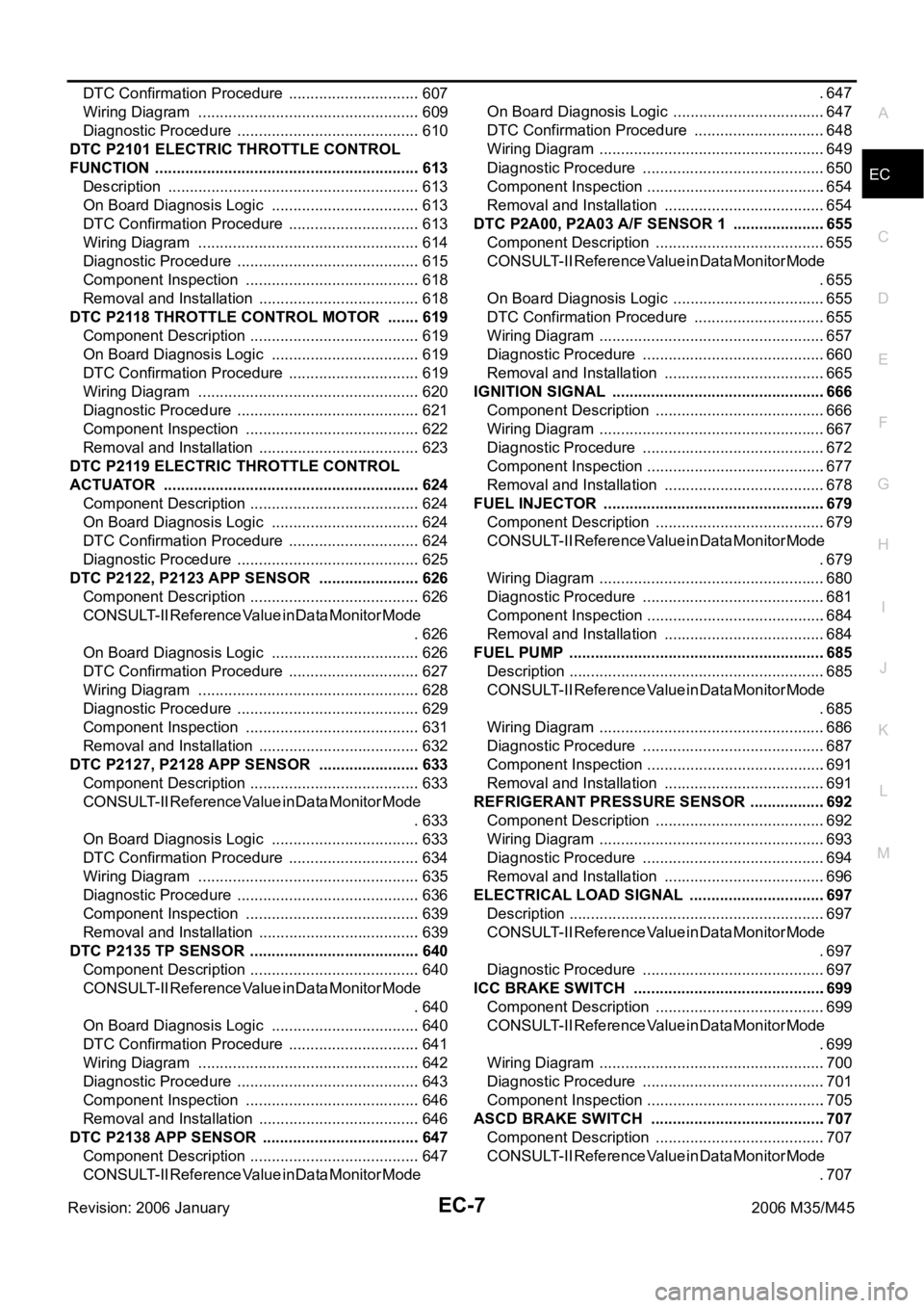
Revision: 2006 January2006 M35/M45 DTC Confirmation Procedure ...............................607
Wiring Diagram ....................................................609
Diagnostic Procedure ...........................................610
DTC P2101 ELECTRIC THROTTLE CONTROL
FUNCTION ..............................................................613
Description ...........................................................613
On Board Diagnosis Logic ...................................613
DTC Confirmation Procedure ...............................613
Wiring Diagram ....................................................614
Diagnostic Procedure ...........................................615
Component Inspection .........................................618
Removal and Installation ......................................618
DTC P2118 THROTTLE CONTROL MOTOR ........619
Component Description ........................................619
On Board Diagnosis Logic ...................................619
DTC Confirmation Procedure ...............................619
Wiring Diagram ....................................................620
Diagnostic Procedure ...........................................621
Component Inspection .........................................622
Removal and Installation ......................................623
DTC P2119 ELECTRIC THROTTLE CONTROL
ACTUATOR ............................................................624
Component Description ........................................624
On Board Diagnosis Logic ...................................624
DTC Confirmation Procedure ...............................624
Diagnostic Procedure ...........................................625
DTC P2122, P2123 APP SENSOR ........................626
Component Description ........................................626
CONSULT-II Reference Value in Data Monitor Mode
.626
On Board Diagnosis Logic ...................................626
DTC Confirmation Procedure ...............................627
Wiring Diagram ....................................................628
Diagnostic Procedure ...........................................629
Component Inspection .........................................631
Removal and Installation ......................................632
DTC P2127, P2128 APP SENSOR ........................633
Component Description ........................................633
CONSULT-II Reference Value in Data Monitor Mode
.633
On Board Diagnosis Logic ...................................633
DTC Confirmation Procedure ...............................634
Wiring Diagram ....................................................635
Diagnostic Procedure ...........................................636
Component Inspection .........................................639
Removal and Installation ......................................639
DTC P2135 TP SENSOR ........................................640
Component Description ........................................640
CONSULT-II Reference Value in Data Monitor Mode
.640
On Board Diagnosis Logic ...................................640
DTC Confirmation Procedure ...............................641
Wiring Diagram ....................................................642
Diagnostic Procedure ...........................................643
Component Inspection .........................................646
Removal and Installation ......................................646
DTC P2138 APP SENSOR .....................................647
Component Description ........................................647
CONSULT-II Reference Value in Data Monitor Mode .647
On Board Diagnosis Logic ....................................647
DTC Confirmation Procedure ...............................648
Wiring Diagram .....................................................649
Diagnostic Procedure ...........................................650
Component Inspection ..........................................654
Removal and Installation ......................................654
DTC P2A00, P2A03 A/F SENSOR 1 ......................655
Component Description ........................................655
CONSULT-II Reference Value in Data Monitor Mode
.655
On Board Diagnosis Logic ....................................655
DTC Confirmation Procedure ...............................655
Wiring Diagram .....................................................657
Diagnostic Procedure ...........................................660
Removal and Installation ......................................665
IGNITION SIGNAL ..................................................666
Component Description ........................................666
Wiring Diagram .....................................................667
Diagnostic Procedure ...........................................672
Component Inspection ..........................................677
Removal and Installation ......................................678
FUEL INJECTOR ....................................................679
Component Description ........................................679
CONSULT-II Reference Value in Data Monitor Mode
.679
Wiring Diagram .....................................................680
Diagnostic Procedure ...........................................681
Component Inspection ..........................................684
Removal and Installation ......................................684
FUEL PUMP ............................................................685
Description ............................................................685
CONSULT-II Reference Value in Data Monitor Mode
.685
Wiring Diagram .....................................................686
Diagnostic Procedure ...........................................687
Component Inspection ..........................................691
Removal and Installation ......................................691
REFRIGERANT PRESSURE SENSOR ..................692
Component Description ........................................692
Wiring Diagram .....................................................693
Diagnostic Procedure ...........................................694
Removal and Installation ......................................696
ELECTRICAL LOAD SIGNAL ................................697
Description ............................................................697
CONSULT-II Reference Value in Data Monitor Mode
.697
Diagnostic Procedure ...........................................697
ICC BRAKE SWITCH .............................................699
Component Description ........................................699
CONSULT-II Reference Value in Data Monitor Mode
.699
Wiring Diagram .....................................................700
Diagnostic Procedure ...........................................701
Component Inspection ..........................................705
ASCD BRAKE SWITCH .........................................707
Component Description ........................................707
CONSULT-II Reference Value in Data Monitor Mode
.707
Page 1551 of 5621

EC-8Revision: 2006 January2006 M35/M45 Wiring Diagram .....................................................708
Diagnostic Procedure ...........................................709
Component Inspection ..........................................713
ASCD INDICATOR .................................................
.714
Component Description ........................................714
CONSULT-II Reference Value in Data Monitor Mode
.714
Wiring Diagram .....................................................715
Diagnostic Procedure ...........................................716
SNOW MODE SWITCH ...........................................717
Description ............................................................717
CONSULT-II Reference Value in the Data Monitor
Mode .....................................................................717
Wiring Diagram .....................................................718
Diagnostic Procedure ...........................................719
Component Inspection ..........................................721
MIL AND DATA LINK CONNECTOR ......................722
Wiring Diagram .....................................................722
SERVICE DATA AND SPECIFICATIONS (SDS) ....724
Fuel Pressure .......................................................724
Idle Speed and Ignition Timing .............................724
Calculated Load Value ..........................................724
Mass Air Flow Sensor ...........................................724
Intake Air Temperature Sensor .............................724
Engine Coolant Temperature Sensor ...................724
Fuel Tank Temperature Sensor ............................724
Crankshaft Position Sensor (POS) .......................724
Camshaft Position Sensor (PHASE) ....................724
A/F Sensor 1 Heater ............................................ .724
Heated Oxygen Sensor 2 Heater .........................725
Throttle Control Motor ...........................................725
Fuel Injector ..........................................................725
Fuel Pump ............................................................725
VK45DE
INDEX FOR DTC .....................................................726
DTC No. Index ......................................................726
Alphabetical Index ................................................730
PRECAUTIONS .......................................................734
Precautions for Supplemental Restraint System
(SRS) “AIR BAG” and “SEAT BELT PRE-TEN-
SIONER” ...............................................................734
Precautions for Procedures without Cowl Top Cover .734
On Board Diagnostic (OBD) System of Engine and
A/T ........................................................................734
Precaution ............................................................735
PREPARATION .......................................................738
Special Service Tools ...........................................738
Commercial Service Tools ....................................739
ENGINE CONTROL SYSTEM ................................740
System Diagram ...................................................740
Multiport Fuel Injection (MFI) System ...................741
Electronic Ignition (EI) System .............................743
Fuel Cut Control (At No Load and High Engine
Speed) ..................................................................744
AIR CONDITIONING CUT CONTROL ....................745
Input/Output Signal Chart .....................................745
System Description ...............................................745AUTOMATIC SPEED CONTROL DEVICE (ASCD) .746
System Description ...............................................746
Component Description ........................................747
CAN COMMUNICATION .........................................748
System Description ...............................................748
EVAPORATIVE EMISSION SYSTEM .....................749
Description ............................................................749
Component Inspection ..........................................752
Removal and Installation .......................................753
How to Detect Fuel Vapor Leakage ......................753
ON BOARD REFUELING VAPOR RECOVERY
(ORVR) ....................................................................756
System Description ...............................................756
Diagnostic Procedure ............................................757
Component Inspection ..........................................759
POSITIVE CRANKCASE VENTILATION ................761
Description ............................................................761
Component Inspection ..........................................761
IVIS (INFINITI VEHICLE IMMOBILIZER SYSTEM-
NATS) ......................................................................763
Description ............................................................763
ON BOARD DIAGNOSTIC (OBD) SYSTEM ...........764
Introduction ..........................................................
.764
Two Trip Detection Logic .......................................764
Emission-Related Diagnostic Information .............765
Malfunction Indicator Lamp (MIL) .........................780
OBD System Operation Chart ...............................782
BASIC SERVICE PROCEDURE .............................788
Basic Inspection ....................................................788
Idle Speed and Ignition Timing Check ..................793
Idle Mixture Ratio Adjustment ...............................795
VIN Registration ....................................................806
Accelerator Pedal Released Position Learning .....806
Throttle Valve Closed Position Learning ...............806
Idle Air Volume Learning .......................................807
Fuel Pressure Check ............................................809
TROUBLE DIAGNOSIS ..........................................811
Trouble Diagnosis Introduction .............................811
DTC Inspection Priority Chart ...............................817
Fail-Safe Chart ......................................................819
Symptom Matrix Chart ..........................................820
Engine Control Component Parts Location ...........824
Vacuum Hose Drawing .........................................833
Circuit Diagram .....................................................834
ECM Harness Connector Terminal Layout ............836
ECM Terminals and Reference Value ...................836
CONSULT-II Function (ENGINE) ..........................846
Generic Scan Tool (GST) Function .......................859
CONSULT-II Reference Value in Data Monitor .....862
Major Sensor Reference Graph in Data Monitor
Mode .....................................................................866
TROUBLE DIAGNOSIS - SPECIFICATION VALUE .868
Description ............................................................868
Testing Condition ..................................................868
Inspection Procedure ...........................................
.868
Diagnostic Procedure ............................................869
TROUBLE DIAGNOSIS FOR INTERMITTENT INCI-
Page 1555 of 5621

EC-12Revision: 2006 January2006 M35/M45 Wiring Diagram ....................................................11 7 2
Diagnostic Procedure ..........................................11 7 3
Component Inspection .........................................11 7 7
DTC P0455 EVAP CONTROL SYSTEM ................117 8
On Board Diagnosis Logic ...................................11 7 8
DTC Confirmation Procedure ..............................11 7 9
Diagnostic Procedure ..........................................11 8 0
DTC P0456 EVAP CONTROL SYSTEM ................118 5
On Board Diagnosis Logic ...................................11 8 5
DTC Confirmation Procedure ..............................11 8 6
Overall Function Check .......................................11 8 7
Diagnostic Procedure ..........................................11 8 8
DTC P0460 FUEL LEVEL SENSOR ......................119 4
Component Description .......................................11 9 4
On Board Diagnosis Logic ...................................11 9 4
DTC Confirmation Procedure ..............................11 9 4
Diagnostic Procedure ..........................................11 9 5
Removal and Installation .....................................11 9 5
DTC P0461 FUEL LEVEL SENSOR ......................119 6
Component Description .......................................11 9 6
On Board Diagnosis Logic ...................................11 9 6
Overall Function Check .......................................11 9 6
Diagnostic Procedure ..........................................11 9 7
Removal and Installation .....................................11 9 7
DTC P0462, P0463 FUEL LEVEL SENSOR CIR-
CUIT .......................................................................119 8
Component Description .......................................11 9 8
On Board Diagnosis Logic ...................................11 9 8
DTC Confirmation Procedure ..............................11 9 8
Diagnostic Procedure ..........................................11 9 9
Removal and Installation .....................................11 9 9
DTC P0500 VSS .....................................................1200
Description ...........................................................1200
On Board Diagnosis Logic ...................................1200
DTC Confirmation Procedure ..............................1200
Overall Function Check .......................................1201
Diagnostic Procedure ..........................................1201
DTC P0506 ISC SYSTEM ......................................1202
Description ...........................................................1202
On Board Diagnosis Logic ...................................1202
DTC Confirmation Procedure ..............................1202
Diagnostic Procedure ..........................................1203
DTC P0507 ISC SYSTEM ......................................1204
Description ...........................................................1204
On Board Diagnosis Logic ...................................1204
DTC Confirmation Procedure ..............................1204
Diagnostic Procedure ..........................................1205
DTC P0550 PSP SENSOR .....................................
1206
Component Description .......................................1206
CONSULT-II Reference Value in Data Monitor Mode
1206
On Board Diagnosis Logic ...................................1206
DTC Confirmation Procedure ..............................1206
Wiring Diagram ....................................................1207
Diagnostic Procedure ..........................................1208
Component Inspection .........................................1210
Removal and Installation .....................................1210
DTC P0603 ECM POWER SUPPLY ......................1211
Component Description .......................................1211On Board Diagnosis Logic ...................................1211
DTC Confirmation Procedure ...............................1211
Wiring Diagram ....................................................1212
Diagnostic Procedure ........................................... 1213
DTC P0605 ECM ....................................................1215
Component Description .......................................1215
On Board Diagnosis Logic ...................................1215
DTC Confirmation Procedure ...............................1215
Diagnostic Procedure ........................................... 1216
DTC P0643 SENSOR POWER SUPPLY ...............1218
On Board Diagnosis Logic ...................................1218
DTC Confirmation Procedure ...............................1218
Wiring Diagram ....................................................1219
Diagnostic Procedure ........................................... 1221
DTC P0850 PNP SWITCH ......................................1223
Component Description .......................................1223
CONSULT-II Reference Value in Data Monitor Mode
1223
On Board Diagnosis Logic ...................................1223
DTC Confirmation Procedure ...............................1223
Overall Function Check ........................................1224
Wiring Diagram ....................................................1225
Diagnostic Procedure ........................................... 1226
DTC P1140, P1145 IVT CONTROL POSITION SEN-
SOR ........................................................................1228
Component Description .......................................1228
CONSULT-II Reference Value in Data Monitor Mode
1228
On Board Diagnosis Logic ...................................1228
DTC Confirmation Procedure ...............................1228
Wiring Diagram ....................................................1229
Diagnostic Procedure ........................................... 1232
Component Inspection .........................................1235
Removal and Installation ......................................1235
DTC P1148, P1168 CLOSED LOOP CONTROL ...1236
On Board Diagnosis Logic ...................................1236
DTC P1211 TCS CONTROL UNIT .........................1237
Description ...........................................................1237
On Board Diagnosis Logic ...................................1237
DTC Confirmation Procedure ...............................1237
Diagnostic Procedure ........................................... 1237
DTC P1212 TCS COMMUNICATION LINE ............1238
Description ...........................................................1238
On Board Diagnosis Logic ...................................1238
DTC Confirmation Procedure ...............................1238
Diagnostic Procedure ........................................... 1238
DTC P1217 ENGINE OVER TEMPERATURE .......1239
Description ...........................................................1239
CONSULT-II Reference Value in Data Monitor Mode
1240
On Board Diagnosis Logic ...................................1240
Overall Function Check ........................................1240
Wiring Diagram ....................................................1242
Diagnostic Procedure ........................................... 1244
Main 13 Causes of Overheating ..........................1249
Component Inspection .........................................1249
DTC P1220 FUEL PUMP CONTROL MODULE
(FPCM) ...................................................................1251
Description ...........................................................1251
Page 1558 of 5621
EC-15
C
D
E
F
G
H
I
J
K
L
M
ECA
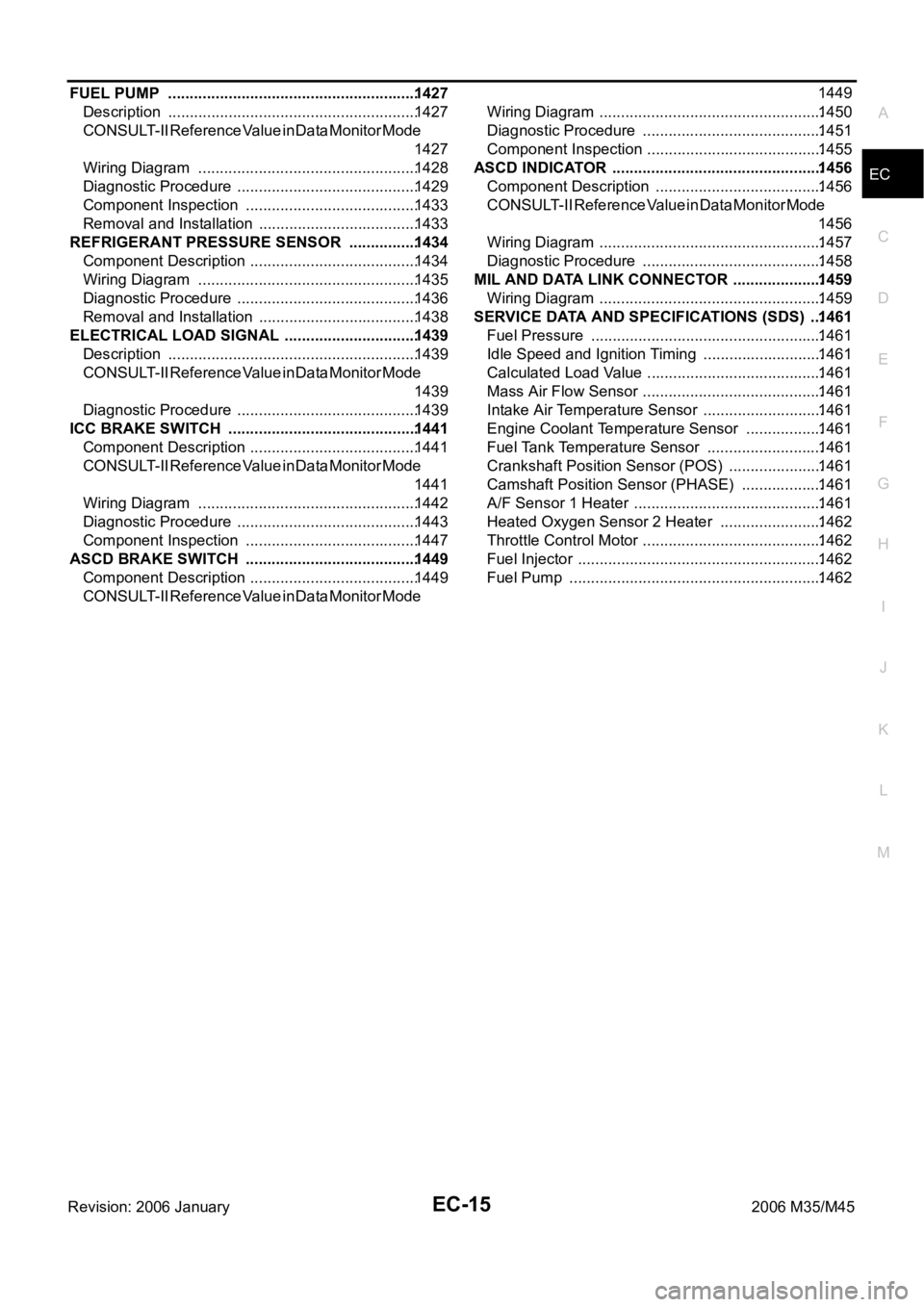
Revision: 2006 January2006 M35/M45 FUEL PUMP ..........................................................1427
Description ..........................................................1427
CONSULT-II Reference Value in Data Monitor Mode
1427
Wiring Diagram ...................................................1428
Diagnostic Procedure ..........................................1429
Component Inspection ........................................1433
Removal and Installation .....................................1433
REFRIGERANT PRESSURE SENSOR ................1434
Component Description .......................................1434
Wiring Diagram ...................................................1435
Diagnostic Procedure ..........................................1436
Removal and Installation .....................................1438
ELECTRICAL LOAD SIGNAL ...............................1439
Description ..........................................................1439
CONSULT-II Reference Value in Data Monitor Mode
1439
Diagnostic Procedure ..........................................1439
ICC BRAKE SWITCH ............................................1441
Component Description .......................................1441
CONSULT-II Reference Value in Data Monitor Mode
1441
Wiring Diagram ...................................................1442
Diagnostic Procedure ..........................................1443
Component Inspection ........................................1447
ASCD BRAKE SWITCH ........................................1449
Component Description .......................................1449
CONSULT-II Reference Value in Data Monitor Mode 1449
Wiring Diagram ....................................................1450
Diagnostic Procedure ..........................................1451
Component Inspection .........................................1455
ASCD INDICATOR ................................................. 1456
Component Description .......................................1456
CONSULT-II Reference Value in Data Monitor Mode
1456
Wiring Diagram ....................................................1457
Diagnostic Procedure ..........................................1458
MIL AND DATA LINK CONNECTOR .....................1459
Wiring Diagram ....................................................1459
SERVICE DATA AND SPECIFICATIONS (SDS) ...1461
Fuel Pressure ......................................................1461
Idle Speed and Ignition Timing ............................1461
Calculated Load Value .........................................1461
Mass Air Flow Sensor ..........................................1461
Intake Air Temperature Sensor ............................1461
Engine Coolant Temperature Sensor ..................1461
Fuel Tank Temperature Sensor ...........................1461
Crankshaft Position Sensor (POS) ......................1461
Camshaft Position Sensor (PHASE) ...................1461
A/F Sensor 1 Heater ............................................ 1461
Heated Oxygen Sensor 2 Heater ........................1462
Throttle Control Motor ..........................................1462
Fuel Injector .........................................................1462
Fuel Pump ...........................................................1462