2006 INFINITI M35 ECU
[x] Cancel search: ECUPage 3356 of 5621
EXHAUST SYSTEM
EX-5
C
D
E
F
G
H
I
J
K
L
MA
EX
Revision: 2006 January2006 M35/M45
Removal and InstallationNBS005RL
CAUTION:
Be sure to use genuine exhaust system parts or equivalents which are specially designed for heat
resistance, corrosion resistance, and shape.
Perform the operation with the exhaust system fully cooled down because the system will be hot
just after engine stops.
Be careful not to cut your hand on the heat insulator edge.
REMOVAL
Disconnect each joint and mounting using power tool.
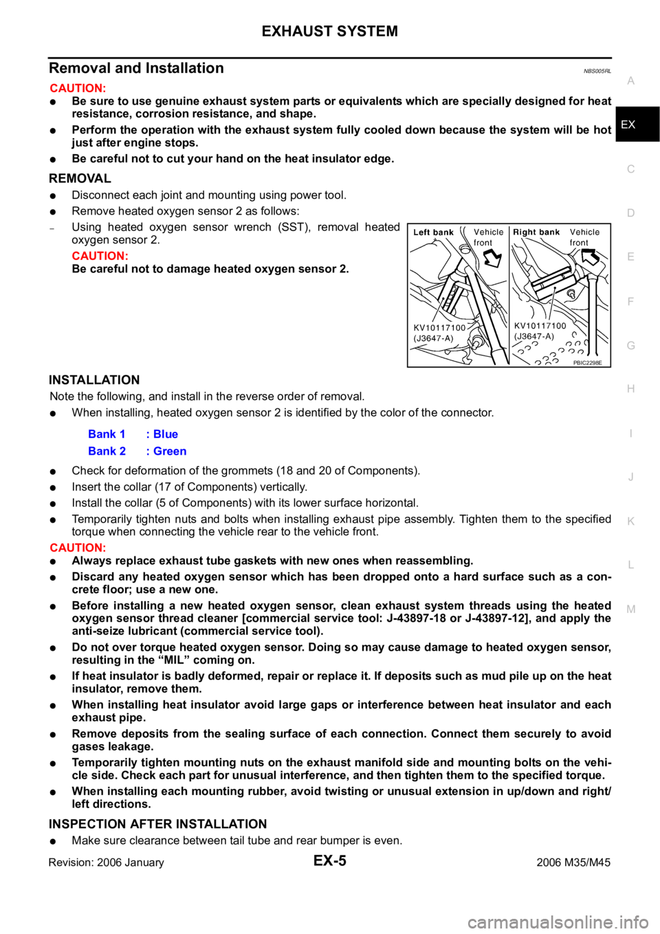
Remove heated oxygen sensor 2 as follows:
–Using heated oxygen sensor wrench (SST), removal heated
oxygen sensor 2.
CAUTION:
Be careful not to damage heated oxygen sensor 2.
INSTALLATION
Note the following, and install in the reverse order of removal.
When installing, heated oxygen sensor 2 is identified by the color of the connector.
Check for deformation of the grommets (18 and 20 of Components).
Insert the collar (17 of Components) vertically.
Install the collar (5 of Components) with its lower surface horizontal.
Temporarily tighten nuts and bolts when installing exhaust pipe assembly. Tighten them to the specified
torque when connecting the vehicle rear to the vehicle front.
CAUTION:
Always replace exhaust tube gaskets with new ones when reassembling.
Discard any heated oxygen sensor which has been dropped onto a hard surface such as a con-
crete floor; use a new one.
Before installing a new heated oxygen sensor, clean exhaust system threads using the heated
oxygen sensor thread cleaner [commercial service tool: J-43897-18 or J-43897-12], and apply the
anti-seize lubricant (commercial service tool).
Do not over torque heated oxygen sensor. Doing so may cause damage to heated oxygen sensor,
resulting in the “MIL” coming on.
If heat insulator is badly deformed, repair or replace it. If deposits such as mud pile up on the heat
insulator, remove them.
When installing heat insulator avoid large gaps or interference between heat insulator and each
exhaust pipe.
Remove deposits from the sealing surface of each connection. Connect them securely to avoid
gases leakage.
Temporarily tighten mounting nuts on the exhaust manifold side and mounting bolts on the vehi-
cle side. Check each part for unusual interference, and then tighten them to the specified torque.
When installing each mounting rubber, avoid twisting or unusual extension in up/down and right/
left directions.
INSPECTION AFTER INSTALLATION
Make sure clearance between tail tube and rear bumper is even.
PBIC2298E
Bank 1 : Blue
Bank 2 : Green
Page 3358 of 5621
EXHAUST SYSTEM
EX-7
C
D
E
F
G
H
I
J
K
L
MA
EX
Revision: 2006 January2006 M35/M45
Removal and installationNBS005RN
CAUTION:
Be sure to use genuine exhaust system parts or equivalents which are specially designed for heat
resistance, corrosion resistance, and shape.
Perform the operation with the exhaust system fully cooled down because the system will be hot
just after engine stops.
Be careful not to cut your hand on the heat insulator edge.
REMOVAL
Disconnect each joint and mounting using power tool.
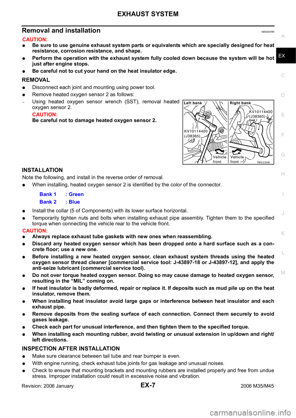
Remove heated oxygen sensor 2 as follows:
–Using heated oxygen sensor wrench (SST), removal heated
oxygen sensor 2.
CAUTION:
Be careful not to damage heated oxygen sensor 2.
INSTALLATION
Note the following, and install in the reverse order of removal.
When installing, heated oxygen sensor 2 is identified by the color of the connector.
Install the collar (5 of Components) with its lower surface horizontal.
Temporarily tighten nuts and bolts when installing exhaust pipe assembly. Tighten them to the specified
torque when connecting the vehicle rear to the vehicle front.
CAUTION:
Always replace exhaust tube gaskets with new ones when reassembling.
Discard any heated oxygen sensor which has been dropped onto a hard surface such as a con-
crete floor; use a new one.
Before installing a new heated oxygen sensor, clean exhaust system threads using the heated
oxygen sensor thread cleaner [commercial service tool: J-43897-18 or J-43897-12], and apply the
anti-seize lubricant (commercial service tool).
Do not over torque heated oxygen sensor. Doing so may cause damage to heated oxygen sensor,
resulting in the “MIL” coming on.
If heat insulator is badly deformed, repair or replace it. If deposits such as mud pile up on the heat
insulator, remove them.
When installing heat insulator avoid large gaps or interference between heat insulator and each
exhaust pipe.
Remove deposits from the sealing surface of each connection. Connect them securely to avoid
gases leakage.
Check each part for unusual interference, and then tighten them to the specified torque.
When installing each mounting rubber, avoid twisting or unusual extension in up/down and right/
left directions.
INSPECTION AFTER INSTALLATION
Make sure clearance between tail tube and rear bumper is even.
With engine running, check exhaust tube joints for gas leakage and unusual noises.
Check to ensure that mounting brackets and mounting rubbers are installed properly and free from undue
stress. Improper installation could result in excessive noise and vibration.
PBIC2334E
Bank 1 : Green
Bank 2 : Blue
Page 3369 of 5621
FAX-10
FRONT DRIVE SHAFT
Revision: 2006 January2006 M35/M45
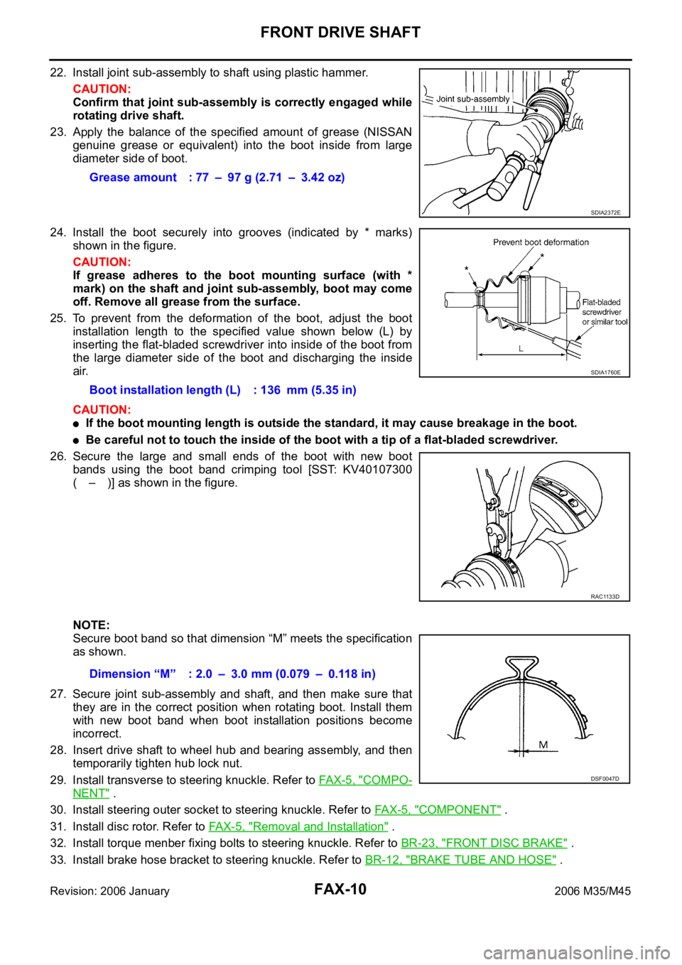
22. Install joint sub-assembly to shaft using plastic hammer.
CAUTION:
Confirm that joint sub-assembly is correctly engaged while
rotating drive shaft.
23. Apply the balance of the specified amount of grease (NISSAN
genuine grease or equivalent) into the boot inside from large
diameter side of boot.
24. Install the boot securely into grooves (indicated by * marks)
shown in the figure.
CAUTION:
If grease adheres to the boot mounting surface (with *
mark) on the shaft and joint sub-assembly, boot may come
off. Remove all grease from the surface.
25. To prevent from the deformation of the boot, adjust the boot
installation length to the specified value shown below (L) by
inserting the flat-bladed screwdriver into inside of the boot from
the large diameter side of the boot and discharging the inside
air.
CAUTION:
If the boot mounting length is outside the standard, it may cause breakage in the boot.
Be careful not to touch the inside of the boot with a tip of a flat-bladed screwdriver.
26. Secure the large and small ends of the boot with new boot
bands using the boot band crimping tool [SST: KV40107300
( – )] as shown in the figure.
NOTE:
Secure boot band so that dimension “M” meets the specification
as shown.
27. Secure joint sub-assembly and shaft, and then make sure that
they are in the correct position when rotating boot. Install them
with new boot band when boot installation positions become
incorrect.
28. Insert drive shaft to wheel hub and bearing assembly, and then
temporarily tighten hub lock nut.
29. Install transverse to steering knuckle. Refer to FAX-5, "
COMPO-
NENT" .
30. Install steering outer socket to steering knuckle. Refer to FA X - 5 , "
COMPONENT" .
31. Install disc rotor. Refer to FA X - 5 , "
Removal and Installation" .
32. Install torque menber fixing bolts to steering knuckle. Refer to BR-23, "
FRONT DISC BRAKE" .
33. Install brake hose bracket to steering knuckle. Refer to BR-12, "
BRAKE TUBE AND HOSE" . Grease amount : 77 – 97 g (2.71 – 3.42 oz)
SDIA2372E
Boot installation length (L) : 136 mm (5.35 in)
SDIA1760E
RAC1133D
Dimension “M” : 2.0 – 3.0 mm (0.079 – 0.118 in)
DSF0047D
Page 3371 of 5621
FAX-12
FRONT DRIVE SHAFT
Revision: 2006 January2006 M35/M45
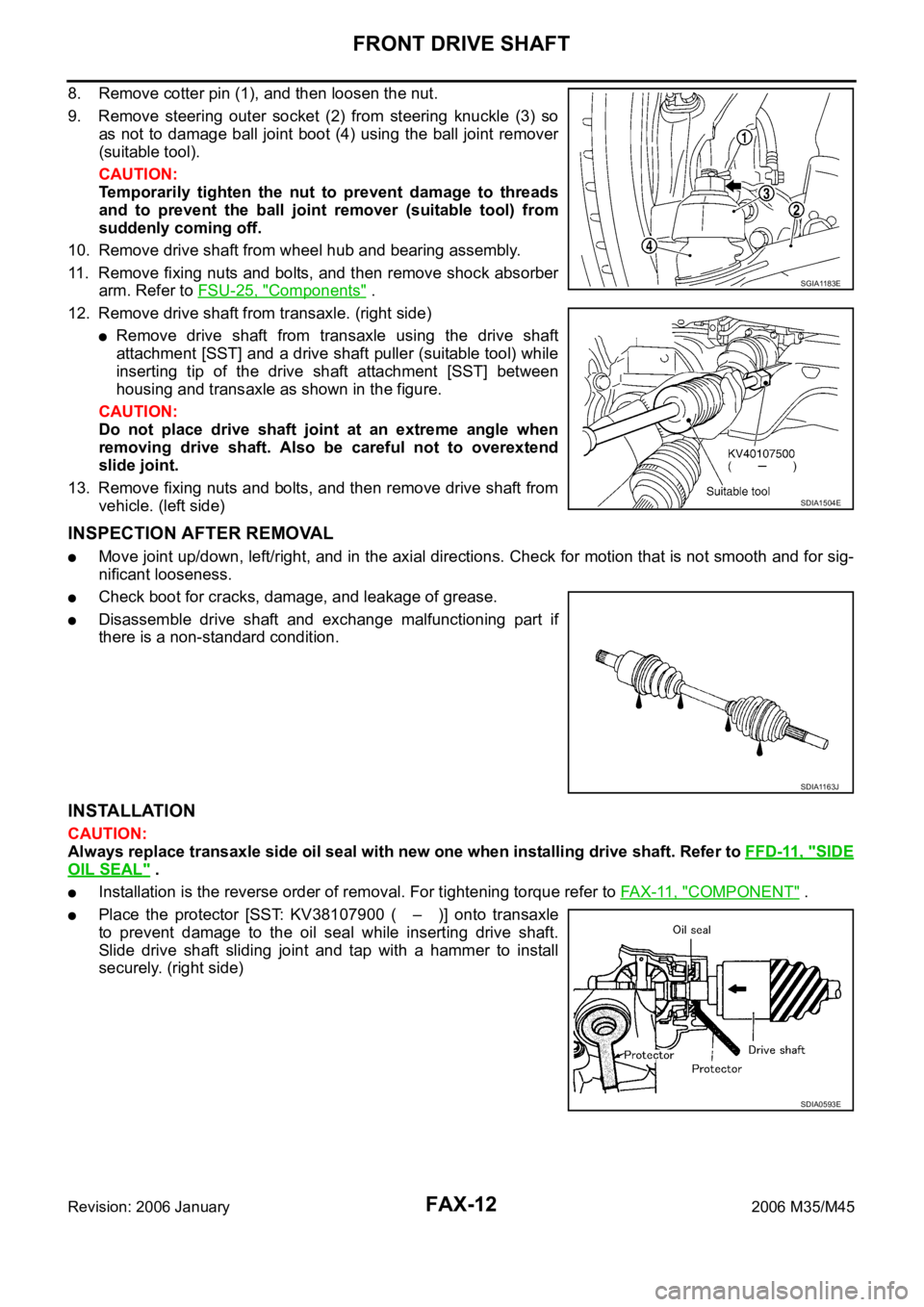
8. Remove cotter pin (1), and then loosen the nut.
9. Remove steering outer socket (2) from steering knuckle (3) so
as not to damage ball joint boot (4) using the ball joint remover
(suitable tool).
CAUTION:
Temporarily tighten the nut to prevent damage to threads
and to prevent the ball joint remover (suitable tool) from
suddenly coming off.
10. Remove drive shaft from wheel hub and bearing assembly.
11. Remove fixing nuts and bolts, and then remove shock absorber
arm. Refer to FSU-25, "
Components" .
12. Remove drive shaft from transaxle. (right side)
Remove drive shaft from transaxle using the drive shaft
attachment [SST] and a drive shaft puller (suitable tool) while
inserting tip of the drive shaft attachment [SST] between
housing and transaxle as shown in the figure.
CAUTION:
Do not place drive shaft joint at an extreme angle when
removing drive shaft. Also be careful not to overextend
slide joint.
13. Remove fixing nuts and bolts, and then remove drive shaft from
vehicle. (left side)
INSPECTION AFTER REMOVAL
Move joint up/down, left/right, and in the axial directions. Check for motion that is not smooth and for sig-
nificant looseness.
Check boot for cracks, damage, and leakage of grease.
Disassemble drive shaft and exchange malfunctioning part if
there is a non-standard condition.
INSTALLATION
CAUTION:
Always replace transaxle side oil seal with new one when installing drive shaft. Refer to FFD-11, "
SIDE
OIL SEAL" .
Installation is the reverse order of removal. For tightening torque refer to FA X - 11 , "COMPONENT" .
Place the protector [SST: KV38107900 ( – )] onto transaxle
to prevent damage to the oil seal while inserting drive shaft.
Slide drive shaft sliding joint and tap with a hammer to install
securely. (right side)
SGIA1183E
SDIA1504E
SDIA1163J
SDIA0593E
Page 3372 of 5621
FRONT DRIVE SHAFT
FAX-13
C
E
F
G
H
I
J
K
L
MA
B
FA X
Revision: 2006 January2006 M35/M45
Disassembly and AssemblyNDS000FJ
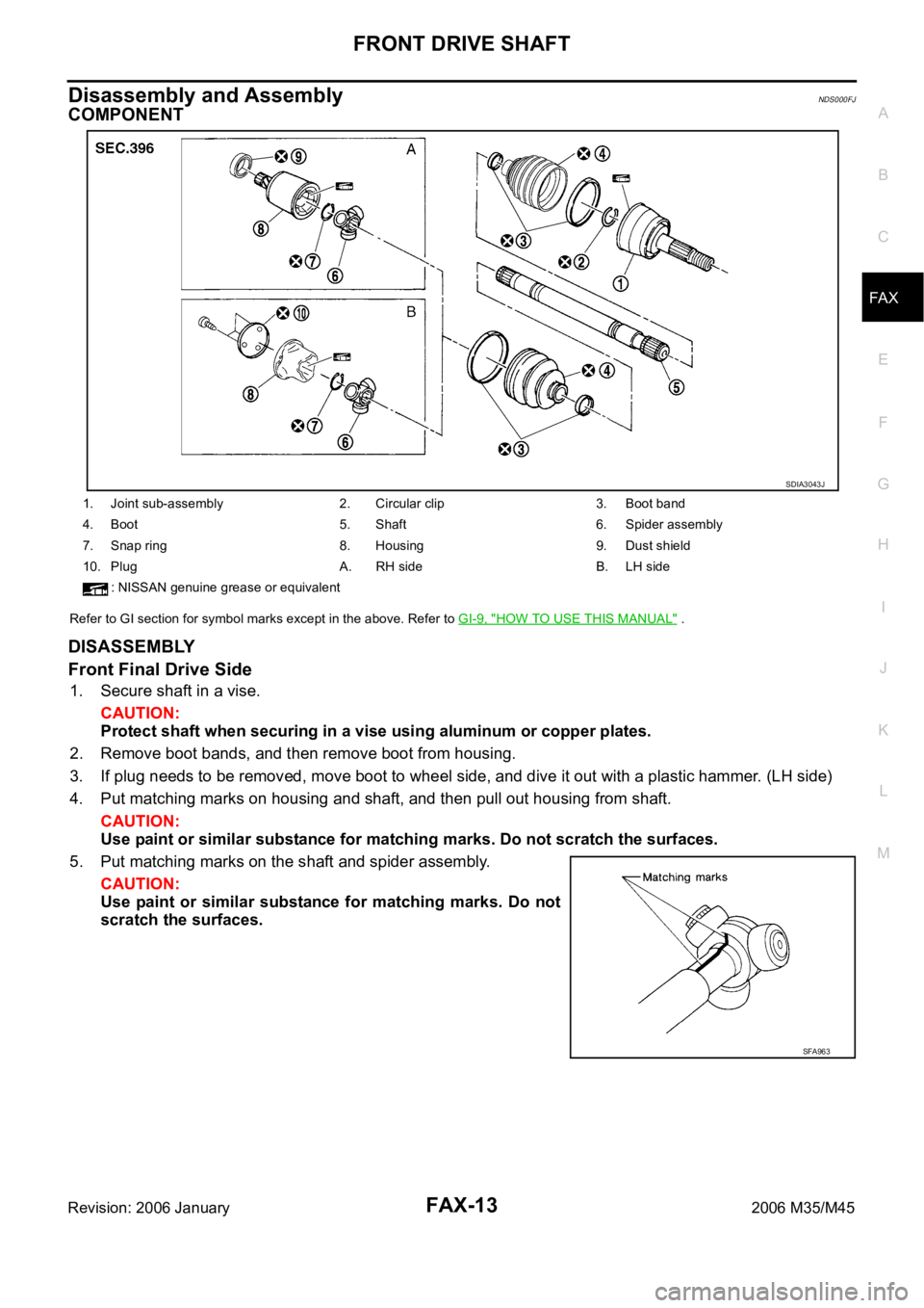
COMPONENT
Refer to GI section for symbol marks except in the above. Refer to GI-9, "HOW TO USE THIS MANUAL" .
DISASSEMBLY
Front Final Drive Side
1. Secure shaft in a vise.
CAUTION:
Protect shaft when securing in a vise using aluminum or copper plates.
2. Remove boot bands, and then remove boot from housing.
3. If plug needs to be removed, move boot to wheel side, and dive it out with a plastic hammer. (LH side)
4. Put matching marks on housing and shaft, and then pull out housing from shaft.
CAUTION:
Use paint or similar substance for matching marks. Do not scratch the surfaces.
5. Put matching marks on the shaft and spider assembly.
CAUTION:
Use paint or similar substance for matching marks. Do not
scratch the surfaces.
1. Joint sub-assembly 2. Circular clip 3. Boot band
4. Boot 5. Shaft 6. Spider assembly
7. Snap ring 8. Housing 9. Dust shield
10. Plug A. RH side B. LH side
: NISSAN genuine grease or equivalent
SDIA3043J
SFA963
Page 3373 of 5621
FAX-14
FRONT DRIVE SHAFT
Revision: 2006 January2006 M35/M45
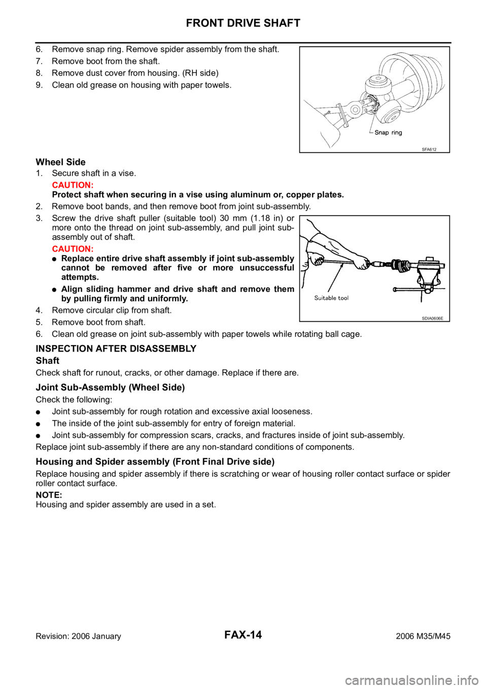
6. Remove snap ring. Remove spider assembly from the shaft.
7. Remove boot from the shaft.
8. Remove dust cover from housing. (RH side)
9. Clean old grease on housing with paper towels.
Wheel Side
1. Secure shaft in a vise.
CAUTION:
Protect shaft when securing in a vise using aluminum or, copper plates.
2. Remove boot bands, and then remove boot from joint sub-assembly.
3. Screw the drive shaft puller (suitable tool) 30 mm (1.18 in) or
more onto the thread on joint sub-assembly, and pull joint sub-
assembly out of shaft.
CAUTION:
Replace entire drive shaft assembly if joint sub-assembly
cannot be removed after five or more unsuccessful
attempts.
Align sliding hammer and drive shaft and remove them
by pulling firmly and uniformly.
4. Remove circular clip from shaft.
5. Remove boot from shaft.
6. Clean old grease on joint sub-assembly with paper towels while rotating ball cage.
INSPECTION AFTER DISASSEMBLY
Shaft
Check shaft for runout, cracks, or other damage. Replace if there are.
Joint Sub-Assembly (Wheel Side)
Check the following:
Joint sub-assembly for rough rotation and excessive axial looseness.
The inside of the joint sub-assembly for entry of foreign material.
Joint sub-assembly for compression scars, cracks, and fractures inside of joint sub-assembly.
Replace joint sub-assembly if there are any non-standard conditions of components.
Housing and Spider assembly (Front Final Drive side)
Replace housing and spider assembly if there is scratching or wear of housing roller contact surface or spider
roller contact surface.
NOTE:
Housing and spider assembly are used in a set.
SFA612
SDIA0606E
Page 3374 of 5621
![INFINITI M35 2006 Factory Service Manual FRONT DRIVE SHAFT
FAX-15
C
E
F
G
H
I
J
K
L
MA
B
FA X
Revision: 2006 January2006 M35/M45
ASSEMBLY
Front Final Drive Side
1. If plug has been removed, use a drift [SST] to press in a new
on INFINITI M35 2006 Factory Service Manual FRONT DRIVE SHAFT
FAX-15
C
E
F
G
H
I
J
K
L
MA
B
FA X
Revision: 2006 January2006 M35/M45
ASSEMBLY
Front Final Drive Side
1. If plug has been removed, use a drift [SST] to press in a new
on](/manual-img/42/57023/w960_57023-3373.png)
FRONT DRIVE SHAFT
FAX-15
C
E
F
G
H
I
J
K
L
MA
B
FA X
Revision: 2006 January2006 M35/M45
ASSEMBLY
Front Final Drive Side
1. If plug has been removed, use a drift [SST] to press in a new
one. (LH side)
2. Wrap serration on shaft with tape to protect boot from damage.
Install new boot and boot bands to shaft.
3. Remove the tape wrapped around the serration on shaft.
4. Align matching marks painted when spider assembly was
removed. Install spider assembly with chamfer facing shaft.
5. Secure spider assembly onto shaft with snap ring.
6. Apply the appropriate amount of grease (NISSAN genuine
grease or equivalent) to spider assembly and sliding surface.
7. Assemble the housing onto spider assembly, and apply the bal-
ance of the specified amount grease (NISSAN genuine grease
or equivalent).
8. Install boot securely into grooves (indicated by * marks) shown in the figure.
CAUTION:
If grease adheres to the boot mounting surface (with * mark) on shaft and housing, boot may come
off. Remove all grease from the surface.
9. To prevent from deformation of the boot, adjust the boot installation length to the value shown below (L) by
inserting a flat-bladed screwdriver or similar tool into the inside of boot from the large diameter side of
boot and discharging inside air.
SDIA1153E
SFA800
SDIA2629E
Grease amount RH side : 113 – 123 g
(3.99–4.34 oz)
LH side : 95 – 105 g
(3.35 – 3.70 oz)
SFA023A
Page 3375 of 5621
FAX-16
FRONT DRIVE SHAFT
Revision: 2006 January2006 M35/M45
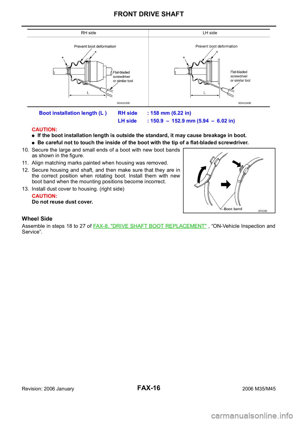
CAUTION:
If the boot installation length is outside the standard, it may cause breakage in boot.
Be careful not to touch the inside of the boot with the tip of a flat-bladed screwdriver.
10. Secure the large and small ends of a boot with new boot bands
as shown in the figure.
11. Align matching marks painted when housing was removed.
12. Secure housing and shaft, and then make sure that they are in
the correct position when rotating boot. Install them with new
boot band when the mounting positions become incorrect.
13. Install dust cover to housing. (right side)
CAUTION:
Do not reuse dust cover.
Wheel Side
Assemble in steps 18 to 27 of FA X - 8 , "DRIVE SHAFT BOOT REPLACEMENT" , “ON-Vehicle Inspection and
Service”.
RH side LH side
Boot installation length (L ) RH side : 158 mm (6.22 in)
LH side : 150.9 – 152.9 mm (5.94 – 6.02 in)
SDIA3250ESDIA3249E
SFA395