2006 INFINITI M35 glove box
[x] Cancel search: glove boxPage 3661 of 5621
IP-12
INSTRUMENT PANEL ASSEMBLY
Revision: 2006 January2006 M35/M45
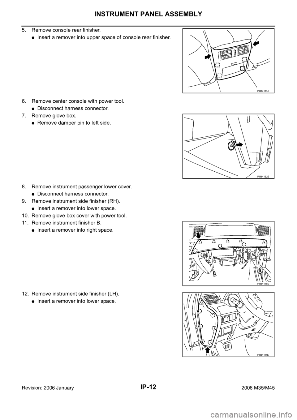
5. Remove console rear finisher.
Insert a remover into upper space of console rear finisher.
6. Remove center console with power tool.
Disconnect harness connector.
7. Remove glove box.
Remove damper pin to left side.
8. Remove instrument passenger lower cover.
Disconnect harness connector.
9. Remove instrument side finisher (RH).
Insert a remover into lower space.
10. Remove glove box cover with power tool.
11. Remove instrument finisher B.
Insert a remover into right space.
12. Remove instrument side finisher (LH).
Insert a remover into lower space.
PIIB4110J
PIIB4152E
PIIB4115E
PIIB4111E
Page 3667 of 5621
IP-18
INSTRUMENT PANEL ASSEMBLY
Revision: 2006 January2006 M35/M45
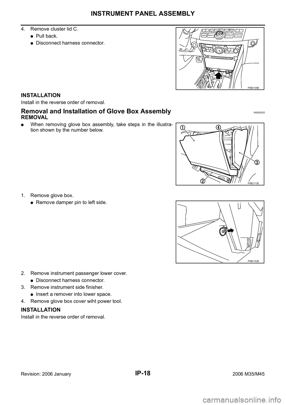
4. Remove cluster lid C.
Pull back.
Disconnect harness connector.
INSTALLATION
Install in the reverse order of removal.
Removal and Installation of Glove Box AssemblyNIS0025G
REMOVAL
When removing glove box assembly, take steps in the illustra-
tion shown by the number below.
1. Remove glove box.
Remove damper pin to left side.
2. Remove instrument passenger lower cover.
Disconnect harness connector.
3. Remove instrument side finisher.
Insert a remover into lower space.
4. Remove glove box cover wiht power tool.
INSTALLATION
Install in the reverse order of removal.
PIIB4109E
PIIB3113E
PIIB4152E
Page 4432 of 5621

LT-5
C
D
E
F
G
H
I
J
L
MA
B
LT
Revision: 2006 January2006 M35/M45 ILLUMINATION OPERATION BY LIGHTING
SWITCH ............................................................296
EXTERIOR LAMP BATTERY SAVER CONTROL .297
CAN Communication System Description ............297
CAN Communication Unit ....................................297
Schematic ............................................................298
Wiring Diagram — ILL — .....................................300
Glove Box Lamp ...................................................313
BULB REPLACEMENT, REMOVAL AND
INSTALLATION .................................................313
Cigarette Lighter Illumination ...............................313
BULB REPLACEMENT, REMOVAL AND INSTALLATION .................................................313
Front Ashtray Illumination .....................................314
BULB REPLACEMENT, REMOVAL AND
INSTALLATION .................................................314
Rear Ashtray Illumination .....................................314
REMOVAL AND INSTALLATION ......................314
INSTALLATION .................................................314
BULB SPECIFICATIONS ........................................315
Headlamp .............................................................315
Exterior Lamp .......................................................315
Interior Lamp/Illumination .....................................315
Page 4723 of 5621

LT-296
ILLUMINATION
Revision: 2006 January2006 M35/M45
ILLUMINATION OPERATION BY LIGHTING SWITCH
With the lighting switch in the 1ST or 2ND position (or if the auto light system is activated), the BCM receives
input signal requesting the illumination lamps to illuminate. This input signal is communicated to the IPDM E/R
across the CAN communication lines. The CPU located in the IPDM E/R controls the tail lamp relay coil,
which, when energized, directs power
through IPDM E/R terminal 21
to combination meter terminal 13
to LDW switch (illumination) terminal 5 (with lane departure warning)
to VDC off switch (illumination) terminal 3
to trunk lid opener switch (illumination) terminal 3
to combination switch (spiral cable) terminal 24
to door mirror remote control switch (illumination) terminal 16
to AFS switch (illumination) terminal 5 (with AFS)
to rear sunshade front switch (illumination) terminal 5 (with rear control switch)
to A/T illumination terminal 1
to snow mode switch (illumination) terminal 5 (AWD models)
to rear control cancel switch (illumination) terminal 4 (with rear control switch)
to clock terminal 3
to multifunction switch terminal 3
to audio unit terminal 9
to DVD player terminal 18 (with DVD player)
to NAVI control unit terminal 61 (with navigation system)
to AV control unit terminal 61 (without navigation system)
to climate controlled seat switch driver side (illumination) terminal 7 (with climate controlled seat)
to climate controlled seat switch passenger side (illumination) terminal 7 (with climate controlled seat)
to ashtray illumination (rear LH) terminal 1
to ashtray illumination (rear RH) terminal 1
to illumination control switch terminal 1
to cigarette lighter socket (illumination) terminal 2
to map lamp (illumination) terminal 8
to power window main switch illumination terminal 1
to glove box lamp terminal 1
to rear control switch terminal 2
to rear power seat switch RH (illumination) terminal 4 (with rear control switch)
to rear heated seat switch RH (illumination) terminal 7 (with rear control switch)
to rear sunshade cancel relay terminal 6 (with rear control switch)
to automatic return cancel switch (illumination) terminal 4 (with rear control switch)
to rear power seat switch LH (illumination) terminal 4 (with rear control switch) and
to rear heated seat switch LH (illumination) terminal 7 (with rear control switch),
through Intelligent Key unit terminal 12
to push button ignition switch (illumination) terminal 3.
Ground is supplied
to combination meter terminal 14
to combination meter terminal 9, 10 and 11
to push button ignition switch (illumination) terminal 2
to LDW switch (illumination) terminal 4 (with lane departure warning)
to VDC off switch (illumination) terminal 4
to trunk lid opener switch (illumination) terminal 4
to combination switch (spiral cable) terminal 25
Page 4724 of 5621
ILLUMINATION
LT-297
C
D
E
F
G
H
I
J
L
MA
B
LT
Revision: 2006 January2006 M35/M45
to door mirror remote control switch (illumination) terminal 15
to AFS switch (illumination) terminal 6 (with AFS)
to rear sunshade front switch (illumination) terminal 6 (with rear control switch)
to A/T illumination terminal 2
to snow mode switch (illumination) terminal 6 (ADW models)
to rear control cancel switch (illumination) terminal 5 (with rear control switch)
to clock terminal 4
to multifunction switch terminal 4
to audio unit terminal 8
to DVD player terminal 17 (With DVD player)
to climate controlled seat switch driver side (illumination) terminal 8 (with climate controlled seat) and
to climate controlled seat switch passenger side (illumination) terminal 8 (with climate controlled seat)
through illumination control switch terminal 2
to illumination control switch terminal 3
through grounds M16 and M70,
to cigarette lighter socket (illumination) terminal 1
to map lamp (illumination) terminal 4
to power window main switch illumination terminal 2 and
to glove box lamp terminal 2
through grounds M16 and M70,
to ashtray illumination (rear LH) terminal 2
to ashtray illumination (rear RH) terminal 2
to automatic return cancel switch (illumination) terminal 2 (With rear control switch)
to rear power seat switch LH (illumination) terminal 3 (With rear control switch)
to rear heated seat switch LH (illumination) terminal 8 (With rear control switch)
through grounds B5, B40 and B131,
through rear sunshade cancel relay terminal 7(With rear control switch)
to rear sunshade rear switch (illumination) terminal 7 (With rear control switch)
through grounds B5, B40, B131 and B559.
to rear control switch terminal 4
to rear power seat switch RH (illumination) terminal 3 (With rear control switch)
to rear heated seat switch RH (illumination) terminal 8 (With rear control switch)
through grounds B5, B40, B131 and B559.
With power and ground supplied, illumination lamps illuminate.
EXTERIOR LAMP BATTERY SAVER CONTROL
BCM activates the exterior lamp battery saver control function and turns off the exterior lamps to prevent bat-
tery from over discharge when the combination switch (lighting switch) is in 1ST or 2ND position and/or the
front fog lamp switch ON and the door lock operation is performed by keyless entry system.
CAN Communication System DescriptionNKS003TI
CAN (Controller Area Network) is a serial communication line for real time application. It is an on-vehicle mul-
tiplex communication line with high data communication speed and excellent error detection ability. Many elec-
tronic control units are equipped onto a vehicle, and each control unit shares information and links with other
control units during operation (not independent). In CAN communication, control units are connected with 2
communication lines (CAN H line, CAN L line) allowing a high rate of information transmission with less wiring.
Each control unit transmits/receives data but selectively reads required data only.
CAN Communication UnitNKS003TJ
Refer to LAN-34, "CAN Communication Unit" .
Page 4740 of 5621
ILLUMINATION
LT-313
C
D
E
F
G
H
I
J
L
MA
B
LT
Revision: 2006 January2006 M35/M45
Glove Box LampNKS003TM
BULB REPLACEMENT, REMOVAL AND INSTALLATION
Removal
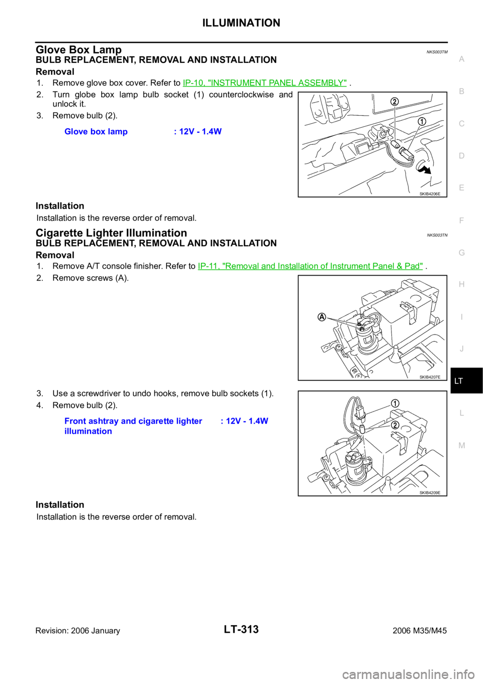
1. Remove glove box cover. Refer to IP-10, "INSTRUMENT PANEL ASSEMBLY" .
2. Turn globe box lamp bulb socket (1) counterclockwise and
unlock it.
3. Remove bulb (2).
Installation
Installation is the reverse order of removal.
Cigarette Lighter IlluminationNKS003TN
BULB REPLACEMENT, REMOVAL AND INSTALLATION
Removal
1. Remove A/T console finisher. Refer to IP-11, "Removal and Installation of Instrument Panel & Pad" .
2. Remove screws (A).
3. Use a screwdriver to undo hooks, remove bulb sockets (1).
4. Remove bulb (2).
Installation
Installation is the reverse order of removal.Glove box lamp : 12V - 1.4W
SKIB4206E
SKIB4207E
Front ashtray and cigarette lighter
illumination: 12V - 1.4W
SKIB4209E
Page 4742 of 5621

BULB SPECIFICATIONS
LT-315
C
D
E
F
G
H
I
J
L
MA
B
LT
Revision: 2006 January2006 M35/M45
BULB SPECIFICATIONSPFP:26297
HeadlampNKS003TQ
Exterior LampNKS003TR
Interior Lamp/IlluminationNKS003TS
NOTE:
This lamp is used as both front ashtray and front cigarette lighter. Item Wattage (W)
Low (Halogen type)55 (H1)
Low (Xenon type)35 (D2S)
High60 (HB3)
Item Wattage (W)
Front combination lampFront turn signal lamp 21
Parking lamp (Clearance lamp) 5
Front side marker lamp 5
Rear combination lampStop/Tail lamp LED
Rear turn signal lamp 21 (amber)
Rear side marker lamp LED
Back-up lamp18
Side turn signal lamp5
Front fog lamp55 (H11)
License plate lamp5
High-mounted stop lampLED
Item Wattage (W)
Map lamp8
Personal lamp8
Trunk room lampUpper
5
Lower
Front ashtray and front cigarette lighter illumination
NOTE1.4
Rear ashtray illumination1.4
Ste p lamp5
Vanity mirror lamp1.8
Center console indirect illuminationLED
Glove box lamp1.4
Foot lampDriver side
3.4
Passenger side
Kicking plateDriver side
LED
Passenger side
Power window indirect illuminationLED
Page 5023 of 5621
RF-10
SUNROOF
Revision: 2006 January2006 M35/M45
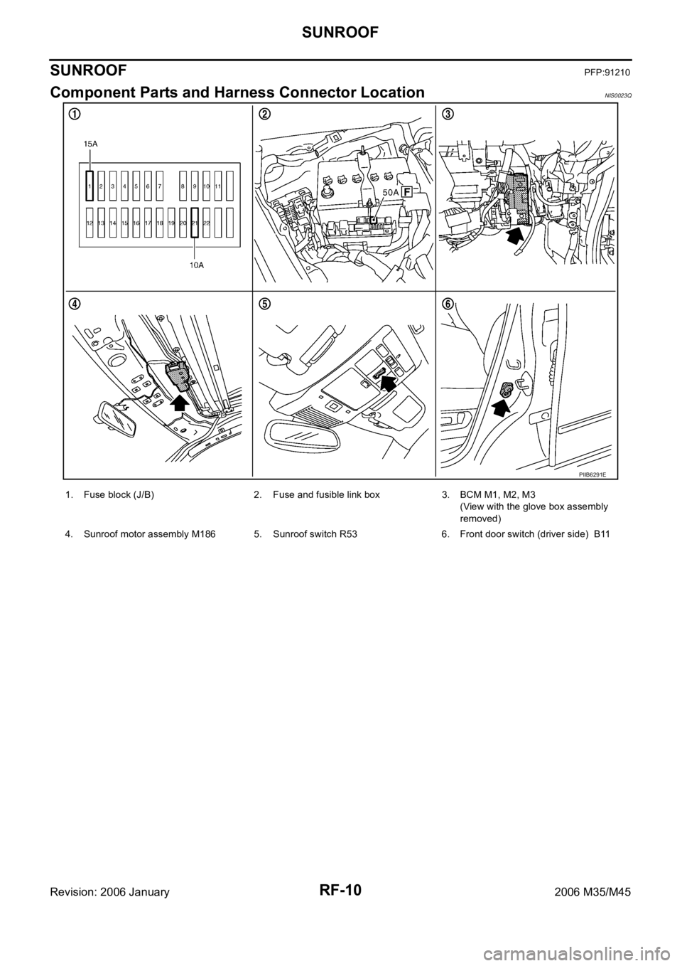
SUNROOFPFP:91210
Component Parts and Harness Connector LocationNIS0023Q
PIIB6291E
1. Fuse block (J/B) 2. Fuse and fusible link box 3. BCM M1, M2, M3
(View with the glove box assembly
removed)
4. Sunroof motor assembly M186 5. Sunroof switch R53 6. Front door switch (driver side) B11