2006 INFINITI M35 glove box
[x] Cancel search: glove boxPage 1148 of 5621

TRUNK LID OPENER
BL-209
C
D
E
F
G
H
J
K
L
MA
B
BL
Revision: 2006 January2006 M35/M45
TRUNK LID OPENERPFP:84640
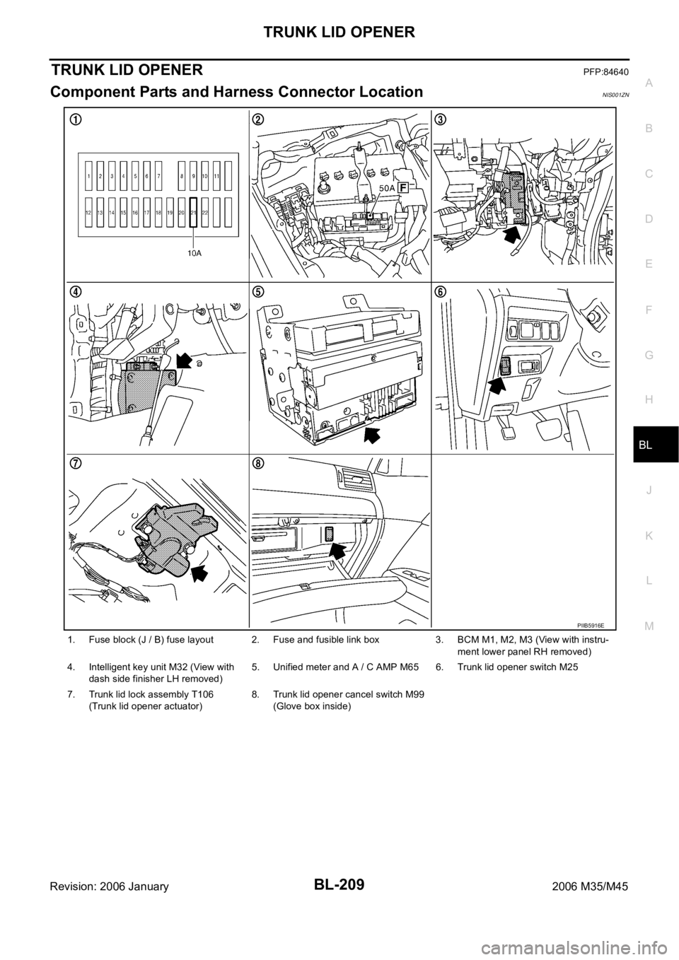
Component Parts and Harness Connector LocationNIS001ZN
1. Fuse block (J / B) fuse layout 2. Fuse and fusible link box 3. BCM M1, M2, M3 (View with instru-
ment lower panel RH removed)
4. Intelligent key unit M32 (View with
dash side finisher LH removed)5. Unified meter and A / C AMP M65 6. Trunk lid opener switch M25
7. Trunk lid lock assembly T106
(Trunk lid opener actuator)8. Trunk lid opener cancel switch M99
(Glove box inside)
PIIB5916E
Page 3177 of 5621
![INFINITI M35 2006 Factory Service Manual EM-114
[VQ35DE]
ENGINE ASSEMBLY
Revision: 2006 January2006 M35/M45
REMOVAL
Outline
At first, remove the engine and the transmission assembly with front suspension member from vehicle down-
ward. Then INFINITI M35 2006 Factory Service Manual EM-114
[VQ35DE]
ENGINE ASSEMBLY
Revision: 2006 January2006 M35/M45
REMOVAL
Outline
At first, remove the engine and the transmission assembly with front suspension member from vehicle down-
ward. Then](/manual-img/42/57023/w960_57023-3176.png)
EM-114
[VQ35DE]
ENGINE ASSEMBLY
Revision: 2006 January2006 M35/M45
REMOVAL
Outline
At first, remove the engine and the transmission assembly with front suspension member from vehicle down-
ward. Then separate the engine from transmission.
Preparation
1. Release fuel pressure. Refer to EC-98, "FUEL PRESSURE RELEASE" .
2. Drain engine coolant from radiator. Refer to CO-11, "
Changing Engine Coolant" .
CAUTION:
Perform this step when engine is cold.
Do not spill engine coolant on drive belts.
3. Disconnect both battery cables. Refer to SC-4, "
BATTERY" .
4. Remove the following parts:
Engine room cover (RH and LH); Refer toEM-14, "ENGINE ROOM COVER" .
Engine cover; Refer to EM-19, "INTAKE MANIFOLD COLLECTOR" .
Front road wheel and tires (power tool)
Front and rear engine undercover (power tool)
Cowl top cover (RH); Refer to EI-18, "COWL TOP" .
Air duct and air cleaner case assembly; EM-17, "AIR CLEANER AND AIR DUCT" .
5. Discharge refrigerant from A/C circuit. Refer to ATC-151, "
REFRIGERANT LINES" .
6. Remove radiator hoses (upper and lower). Refer to CO-14, "
RADIATOR" .
Engine Room LH
1. Disconnect heater hose from vehicle-side, and fit a plug onto hose end to prevent engine coolant leak.
2. Disconnect wire bonding (between vehicle to left bank cylinder head).
3. Disconnect A/C piping from A/C compressor, and temporarily fasten it on vehicle with a rope. Refer to
AT C - 1 5 1 , "
REFRIGERANT LINES" .
4. Disconnect brake booster vacuum hose.
Engine Room RH
1. Disconnect battery positive cable at vehicle side and temporarily fasten it on engine.
2. Disconnect grounding cable.
3. Disconnect fuel feed hose (with damper) and EVAP hose. Refer to EM-45, "
FUEL INJECTOR AND FUEL
TUBE" .
CAUTION:
Fit plugs onto disconnected hoses to prevent fuel leak.
4. Remove reservoir tank of power steering oil pump and piping from vehicle, and temporarily secure them
on engine. Refer to PS-29, "
POWER STEERING OIL PUMP" .
CAUTION:
When temporarily securing, keep the reservoir tank upright to avoid a fluid leak.
Vehicle inside
Follow procedure below to disconnect engine room harness connectors at passenger room side, and tempo-
rarily secure them on engine.
1. Remove passenger-side kicking plate, dash side finisher, and glove box. Refer to EI-37, "
BODY SIDE
TRIM" and IP-10, "INSTRUMENT PANEL ASSEMBLY" .
2. Disconnect engine room harness connectors at unit sides TCM, ECM and other.
3. Disengage intermediate fixing point. Pull out engine room harnesses to engine room side, and temporarily
secure them on engine.
CAUTION:
When pulling out harnesses, take care not to damage harnesses and connectors.
After temporarily securing, cover connectors with vinyl or similar material to protect against for-
eign material adhesion.
Page 3183 of 5621
![INFINITI M35 2006 Factory Service Manual EM-120
[VQ35DE]
ENGINE ASSEMBLY
Revision: 2006 January2006 M35/M45
1. Remove passenger-side kicking plate, dash side finisher, and glove box. Refer to EI-37, "BODY SIDE
TRIM" and INFINITI M35 2006 Factory Service Manual EM-120
[VQ35DE]
ENGINE ASSEMBLY
Revision: 2006 January2006 M35/M45
1. Remove passenger-side kicking plate, dash side finisher, and glove box. Refer to EI-37, "BODY SIDE
TRIM" and](/manual-img/42/57023/w960_57023-3182.png)
EM-120
[VQ35DE]
ENGINE ASSEMBLY
Revision: 2006 January2006 M35/M45
1. Remove passenger-side kicking plate, dash side finisher, and glove box. Refer to EI-37, "BODY SIDE
TRIM" and IP-10, "INSTRUMENT PANEL ASSEMBLY" .
2. Disconnect engine room harness connectors at unit sides TCM, ECM and other.
3. Disengage intermediate fixing point. Pull out engine room harnesses to engine room side, and temporarily
secure them on engine.
CAUTION:
When pulling out harnesses, take care not to damage harnesses and connectors.
After temporarily securing, cover connectors with vinyl or similar material to protect against for-
eign material adhesion.
Vehicle Underbody
1. Remove A/T fluid cooler hoses and power steering oil pump oil cooler hoses.
Install plug to avoid leakage of A/T fluid and power steering fluid.
2. Disconnect heated oxygen sensor 2 harness. Refer to EX-3, "
EXHAUST SYSTEM" .
3. Remove three way catalyst and exhaust front tube. Refer to EX-3, "
EXHAUST SYSTEM" .
4. Disconnect steering lower joint at power steering gear assembly side, and release steering lower shaft.
Refer to PS-13, "
STEERING COLUMN" .
5. Remove rear propeller shaft. Refer to PR-6, "
REAR PROPELLER SHAFT" .
6. Remove front drive shaft (both side). Refer to FAX-8, "
FRONT DRIVE SHAFT" .
7. Disconnect harness connector from transmission assembly and transfer assembly.
8. Disengage A/T control rod at control device assembly side. Then, temporarily secure it on the transmis-
sion assembly, so that it does not sag. Refer to AT-222, "
SHIFT CONTROL SYSTEM" .
9. Remove rear plate cover from oil pan (upper). Then remove bolts fixing drive plate to torque converter.
Refer to EM-29, "
OIL PAN AND OIL STRAINER" and AT-271, "TRANSMISSION ASSEMBLY" .
10. Remove bolts fixing the transmission assembly to lower rear side of oil pan (upper). Refer to AT- 2 7 1 ,
"TRANSMISSION ASSEMBLY" .
11. Remove front stabilizer at transverse link side. Refer to FSU-18, "
STABILIZER BAR" .
12. Remove lower ends of left and right strut from transverse link. Refer to FSU-23, "
FRONT SUSPENSION
ASSEMBLY" .
13. Separate steering outer sockets from steering knuckle. Refer to PS-18, "
POWER STEERING GEAR" .
14. Remove transverse links mounting bolts at knuckle side. Refer to FSU-31, "
TRANSVERSE LINK" .
Removal Work
1. Use a manual lift table caddy (commercial service tool) or equiv-
alently rigid tool such as a transmission jack. Securely support
bottom of suspension member and transmission.
CAUTION:
Put a piece of wood or something similar as the supporting
surface, secure a completely stable condition.
2. Remove rear engine mounting member bolts.
3. Remove front suspension member mounting bolts and nuts. Refer to FSU-23, "
FRONT SUSPENSION
ASSEMBLY" .
4. Carefully lower jack, or raise lift to remove the engine, transmission assembly, transfer, front final drive
assembly and front suspension member. When performing work, observe the following caution:
CAUTION:
Confirm there is no interference with the vehicle.
Make sure that all connection points have been disconnected.
Keep in mind the center of the vehicle gravity changes. If necessary, use jack(s) to support the
vehicle at rear jacking point(s) to prevent it from falling it off the lift.
PBIC0804E
Page 3308 of 5621
![INFINITI M35 2006 Factory Service Manual ENGINE ASSEMBLY
EM-245
[VK45DE]
C
D
E
F
G
H
I
J
K
L
MA
EM
Revision: 2006 January2006 M35/M45
Always use the support point specified for lifting.
Use either 2-pole lift type or separate type li INFINITI M35 2006 Factory Service Manual ENGINE ASSEMBLY
EM-245
[VK45DE]
C
D
E
F
G
H
I
J
K
L
MA
EM
Revision: 2006 January2006 M35/M45
Always use the support point specified for lifting.
Use either 2-pole lift type or separate type li](/manual-img/42/57023/w960_57023-3307.png)
ENGINE ASSEMBLY
EM-245
[VK45DE]
C
D
E
F
G
H
I
J
K
L
MA
EM
Revision: 2006 January2006 M35/M45
Always use the support point specified for lifting.
Use either 2-pole lift type or separate type lift as best you can. If board-on type is used for
unavoidable reasons, support at the rear axle jacking point with transmission jack or similar tool
before starting work, in preparation for the backward shift of center of gravity.
For supporting points for lifting and jacking point at rear axle, refer to GI-42, "Garage Jack and
Safety Stand and 2-Pole Lift" .
REMOVAL
Outline
At first, remove engine, transmission assembly with front suspension member from vehicle downward. Then
separate engine from transmission.
Preparation
1. Release fuel pressure. Refer to EC-809, "FUEL PRESSURE RELEASE" .
2. Drain engine coolant from radiator. Refer to CO-40, "
Changing Engine Coolant" .
CAUTION:
Perform this step when engine is cold.
Do not spill engine coolant on drive belts.
3. Disconnect both battery cables. Refer to SC-4, "
BATTERY" .
4. Remove crankshaft position sensor (POS) from transmission.
CAUTION:
Handle carefully to avoid dropping and shocks.
Do not disassemble.
Do not allow metal powder to adhere to magnetic part at sensor tip.
Do not place sensors in a location where they are exposed to magnetism.
5. Remove the following parts:
Front and rear engine undercover (power tool)
Air duct (inlet), air duct and air cleaner case assembly; Refer to EM-177, "AIR CLEANER AND AIR
DUCT" .
Front road wheels and tires (power tool)
Engine Room LH
1. Disconnect heater hoses, and install plugs to avoid leakage of engine coolant.
2. Disconnect wire bonding from exhaust manifold cover to vehicle.
3. Disconnect vacuum hose between vehicle and engine and set it aside.
4. Discharge refrigerant from A/C circuit. Refer to ATC-151, "
REFRIGERANT LINES" .
5. Remove A/C piping from A/C compressor, and temporarily fasten it on vehicle with a rope. Refer to AT C -
151, "REFRIGERANT LINES" .
Engine Room RH
1. Disconnect fuel feed hose and EVAP hose. Refer to EM-193, "FUEL INJECTOR AND FUEL TUBE" .
CAUTION:
Fit plugs onto disconnected hose to prevent fuel leak.
2. Disconnect ground cable (between vehicle and right bank cylinder head).
3. Disconnect vacuum hose between vehicle and engine and set it aside.
4. Disconnect reservoir tank of power steering oil pump from engine, and move it aside for easier work.
CAUTION:
When temporarily securing, keep reservoir tank upright to avoid a fluid leak.
Ve h i c le i n s i d e
Follow procedure below to disconnect engine room harness connectors at passenger room side, and tempo-
rarily secure them on engine.
1. Remove passenger-side kicking plate, dash side finisher, and glove box. Refer to EI-37, "
BODY SIDE
TRIM" and IP-10, "INSTRUMENT PANEL ASSEMBLY" .
2. Disconnect engine room harness connectors at unit sides TCM, ECM and other.
Page 3531 of 5621

GW-12
WINDSHIELD GLASS
Revision: 2006 January2006 M35/M45
4. Remove the cowl top cover. Refer to EI-18, "COWL TOP" .
5. Remove roof side molding. Refer to EI-25, "
ROOF SIDE MOLDING" .
6. Apply a protective tape around the windshield glass to protect the painted surface from damage.
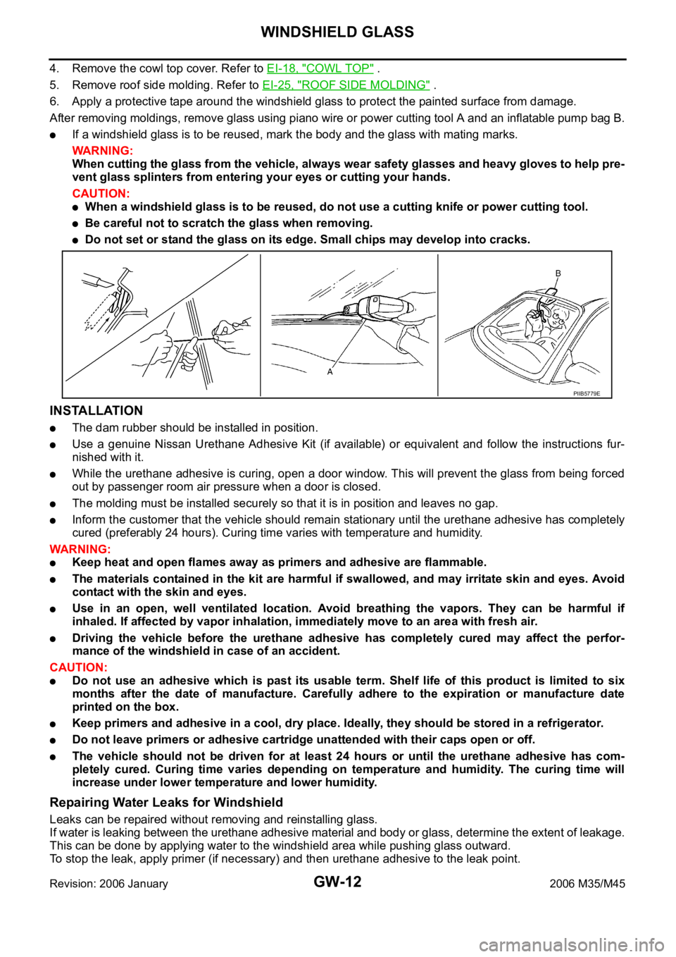
After removing moldings, remove glass using piano wire or power cutting tool A and an inflatable pump bag B.
If a windshield glass is to be reused, mark the body and the glass with mating marks.
WA R N I N G :
When cutting the glass from the vehicle, always wear safety glasses and heavy gloves to help pre-
vent glass splinters from entering your eyes or cutting your hands.
CAUTION:
When a windshield glass is to be reused, do not use a cutting knife or power cutting tool.
Be careful not to scratch the glass when removing.
Do not set or stand the glass on its edge. Small chips may develop into cracks.
INSTALLATION
The dam rubber should be installed in position.
Use a genuine Nissan Urethane Adhesive Kit (if available) or equivalent and follow the instructions fur-
nished with it.
While the urethane adhesive is curing, open a door window. This will prevent the glass from being forced
out by passenger room air pressure when a door is closed.
The molding must be installed securely so that it is in position and leaves no gap.
Inform the customer that the vehicle should remain stationary until the urethane adhesive has completely
cured (preferably 24 hours). Curing time varies with temperature and humidity.
WAR NING :
Keep heat and open flames away as primers and adhesive are flammable.
The materials contained in the kit are harmful if swallowed, and may irritate skin and eyes. Avoid
contact with the skin and eyes.
Use in an open, well ventilated location. Avoid breathing the vapors. They can be harmful if
inhaled. If affected by vapor inhalation, immediately move to an area with fresh air.
Driving the vehicle before the urethane adhesive has completely cured may affect the perfor-
mance of the windshield in case of an accident.
CAUTION:
Do not use an adhesive which is past its usable term. Shelf life of this product is limited to six
months after the date of manufacture. Carefully adhere to the expiration or manufacture date
printed on the box.
Keep primers and adhesive in a cool, dry place. Ideally, they should be stored in a refrigerator.
Do not leave primers or adhesive cartridge unattended with their caps open or off.
The vehicle should not be driven for at least 24 hours or until the urethane adhesive has com-
pletely cured. Curing time varies depending on temperature and humidity. The curing time will
increase under lower temperature and lower humidity.
Repairing Water Leaks for Windshield
Leaks can be repaired without removing and reinstalling glass.
If water is leaking between the urethane adhesive material and body or glass, determine the extent of leakage.
This can be done by applying water to the windshield area while pushing glass outward.
To stop the leak, apply primer (if necessary) and then urethane adhesive to the leak point.
PIIB5779E
Page 3581 of 5621

GW-62
REAR WINDOW GLASS AND MOLDING
Revision: 2006 January2006 M35/M45
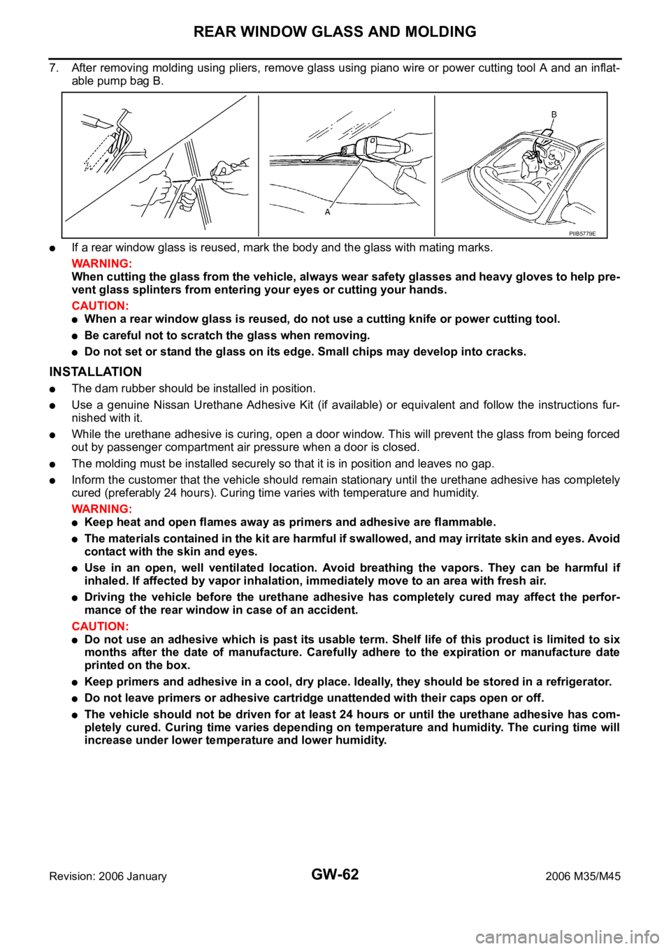
7. After removing molding using pliers, remove glass using piano wire or power cutting tool A and an inflat-
able pump bag B.
If a rear window glass is reused, mark the body and the glass with mating marks.
WA R N I N G :
When cutting the glass from the vehicle, always wear safety glasses and heavy gloves to help pre-
vent glass splinters from entering your eyes or cutting your hands.
CAUTION:
When a rear window glass is reused, do not use a cutting knife or power cutting tool.
Be careful not to scratch the glass when removing.
Do not set or stand the glass on its edge. Small chips may develop into cracks.
INSTALLATION
The dam rubber should be installed in position.
Use a genuine Nissan Urethane Adhesive Kit (if available) or equivalent and follow the instructions fur-
nished with it.
While the urethane adhesive is curing, open a door window. This will prevent the glass from being forced
out by passenger compartment air pressure when a door is closed.
The molding must be installed securely so that it is in position and leaves no gap.
Inform the customer that the vehicle should remain stationary until the urethane adhesive has completely
cured (preferably 24 hours). Curing time varies with temperature and humidity.
WA R N I N G :
Keep heat and open flames away as primers and adhesive are flammable.
The materials contained in the kit are harmful if swallowed, and may irritate skin and eyes. Avoid
contact with the skin and eyes.
Use in an open, well ventilated location. Avoid breathing the vapors. They can be harmful if
inhaled. If affected by vapor inhalation, immediately move to an area with fresh air.
Driving the vehicle before the urethane adhesive has completely cured may affect the perfor-
mance of the rear window in case of an accident.
CAUTION:
Do not use an adhesive which is past its usable term. Shelf life of this product is limited to six
months after the date of manufacture. Carefully adhere to the expiration or manufacture date
printed on the box.
Keep primers and adhesive in a cool, dry place. Ideally, they should be stored in a refrigerator.
Do not leave primers or adhesive cartridge unattended with their caps open or off.
The vehicle should not be driven for at least 24 hours or until the urethane adhesive has com-
pletely cured. Curing time varies depending on temperature and humidity. The curing time will
increase under lower temperature and lower humidity.
PIIB5779E
Page 3650 of 5621

IP-1
INSTRUMENT PANEL
I BODY
CONTENTS
C
D
E
F
G
H
J
K
L
M
SECTION IP
A
B
IP
Revision: 2006 January2006 M35/M45
INSTRUMENT PANEL
PRECAUTIONS .......................................................... 2
Precautions for Supplemental Restraint System
(SRS) “AIR BAG” and “SEAT BELT PRE-TEN-
SIONER” .................................................................. 2
Precautions .............................................................. 2
PREPARATION ........................................................... 3
Special Service Tools ............................................... 3
Commercial Service Tools ........................................ 3
SQUEAK AND RATTLE TROUBLE DIAGNOSES ..... 4
Work Flow ................................................................ 4
CUSTOMER INTERVIEW ..................................... 4
DUPLICATE THE NOISE AND TEST DRIVE ....... 5
CHECK RELATED SERVICE BULLETINS ........... 5
LOCATE THE NOISE AND IDENTIFY THE
ROOT CAUSE ...................................................... 5
REPAIR THE CAUSE ........................................... 5
CONFIRM THE REPAIR ....................................... 6
Generic Squeak and Rattle Troubleshooting ........... 6
INSTRUMENT PANEL .......................................... 6
CENTER CONSOLE ............................................. 6
DOORS ................................................................. 6TRUNK .................................................................. 7
SUNROOF/HEADLINING ..................................... 7
SEATS ................................................................... 7
UNDERHOOD ....................................................... 7
Diagnostic Worksheet ............................................... 8
INSTRUMENT PANEL ASSEMBLY ......................... 10
Component Parts Drawing ..................................... 10
Removal and Installation of Instrument Panel & Pad ... 11
REMOVAL ........................................................
... 11
INSTALLATION ................................................... 14
Removal and Installation of Cluster Lid A ............... 15
REMOVAL ........................................................
... 15
INSTALLATION ................................................... 16
Removal and Installation of Cluster Lid C .............. 17
REMOVAL ........................................................
... 17
INSTALLATION ................................................... 18
Removal and Installation of Glove Box Assembly ... 18
REMOVAL ........................................................
... 18
INSTALLATION ................................................... 18
Disassembly and Assembly .................................... 19
CENTER CONSOLE ASSEMBLY ....................... 19
Page 3660 of 5621

INSTRUMENT PANEL ASSEMBLY
IP-11
C
D
E
F
G
H
J
K
L
MA
B
IP
Revision: 2006 January2006 M35/M45
Removal and Installation of Instrument Panel & PadNIS0025D
REMOVAL
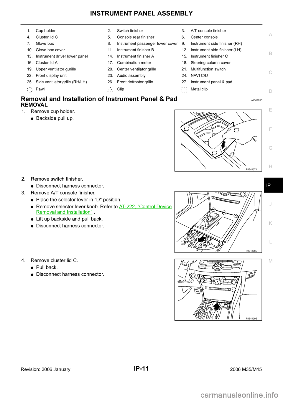
1. Remove cup holder.
Backside pull up.
2. Remove switch finisher.
Disconnect harness connector.
3. Remove A/T console finisher.
Place the selector lever in "D" position.
Remove selector lever knob. Refer to AT- 2 2 2 , "Control Device
Removal and Installation" .
Lift up backside and pull back.
Disconnect harness connector.
4. Remove cluster lid C.
Pull back.
Disconnect harness connector.
1. Cup holder 2. Switch finisher 3. A/T console finisher
4. Cluster lid C 5. Console rear finisher 6. Center console
7. Glove box 8. Instrument passenger lower cover 9. Instrument side finisher (RH)
10. Glove box cover 11. Instrument finisher B 12. Instrument side finisher (LH)
13. Instrument driver lower panel 14. Instrument finisher A 15. Instrument finisher C
16. Cluster lid A 17. Combination meter 18. Steering column cover
19. Upper ventilator gurille 20. Center ventilator grille 21. Multifunction switch
22. Front display unit 23. Audio assembly 24. NAVI C/U
25. Side ventilator grille (RH/LH) 26. Front defroster grille 27. Instrument panel & pad
Pawl Clip Metal clip
PIIB4107J
PIIB4108E
PIIB4109E