Page 5192 of 5621
AUTOMATIC DRIVE POSITIONER
SE-11
C
D
E
F
G
H
J
K
L
MA
B
SE
Revision: 2006 January2006 M35/M45
AUTOMATIC DRIVE POSITIONERPFP:28491
Component Parts And Harness Connector LocationNIS0025Q
PIIB6292E
1. Fuse block (J/B) 2. Fuse and fusible link box 3. BCM M1, M2, M3
(View with the glove box assembly
removed)
4. A. Automatic drive positioner control
unit M6, M7
B. Telescopic motor M45
C. Telescopic sensor M44
D. Tilt sensor M37
E. Tilt motor M36
(View with the driver lower panel
removed)5. A. Front lifting motor B209
B. Rear lifting motor B208
C. Driver seat control unit
B204,B205
D. Sliding motor B2076. Seat memory switch D9
7. A. Lumbar support switch B212
B. Reclining switch B213
C. Sliding/Lifting switch B2138. A. ADP steering switch M46
B. Key slot M14
C. Door mirror control switch M959. Reclining motor B208
Page 5272 of 5621
POWER SEAT(PASSENGER SIDE)
SE-91
C
D
E
F
G
H
J
K
L
MA
B
SE
Revision: 2006 January2006 M35/M45
POWER SEAT(PASSENGER SIDE)PFP:87050
Component Parts and Harness Connector LocationNIS0026Z
PIIB5888E
1. Fuse block (J/B) 2.Fuse, fusible link and relay block (J/
B)3.BCM M2
(View with the glove box cover
removed)
4.Power seat switch B255
a: Reclining switch
b: Sliding and lifting switch5.a: Sliding motor M264
b: Lifting motor M2666. Reclining motor M263
Page 5403 of 5621

SRS-42
FRONT PASSENGER AIR BAG MODULE
Revision: 2006 January2006 M35/M45
FRONT PASSENGER AIR BAG MODULEPFP:K8515
Removal and InstallationNHS0009E
REMOVAL
CAUTION:
Before servicing, turn ignition switch OFF, disconnect both battery terminal and wait at
least 3 minutes.
Do not use air tools or electric tools for servicing.
Always work from the side of air bag module. Do not work from the front of it.
Always place air bag module with pad side facing upward.
Do not use old fixing bolts after removal; replace with new bolts.
Do not make an impact to the air bag module by dropping etc. Replace the air bag module if it has
been dropped or sustained an impact.
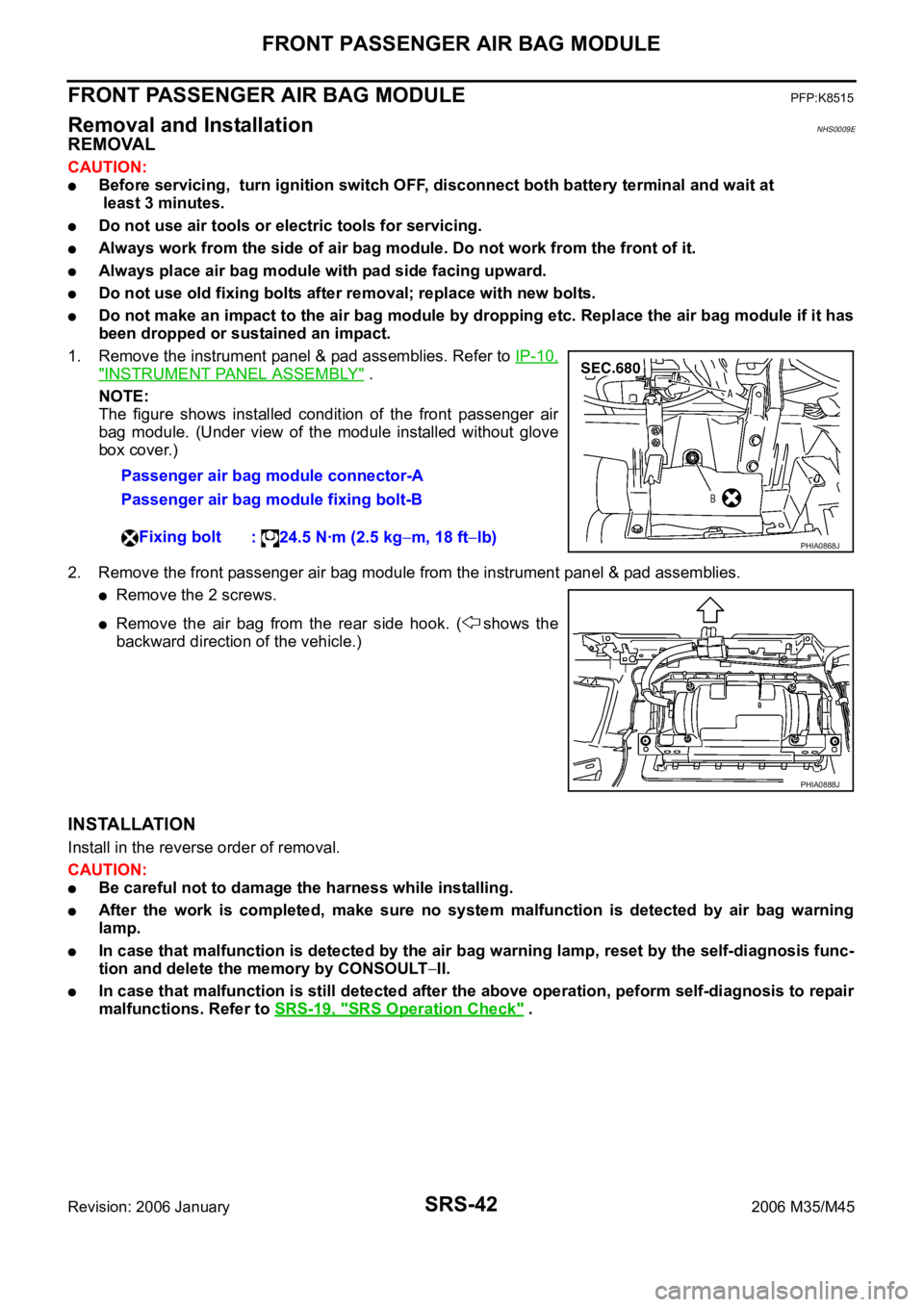
1. Remove the instrument panel & pad assemblies. Refer to IP-10,
"INSTRUMENT PANEL ASSEMBLY" .
NOTE:
The figure shows installed condition of the front passenger air
bag module. (Under view of the module installed without glove
box cover.)
2. Remove the front passenger air bag module from the instrument panel & pad assemblies.
Remove the 2 screws.
Remove the air bag from the rear side hook. ( shows the
backward direction of the vehicle.)
INSTALLATION
Install in the reverse order of removal.
CAUTION:
Be careful not to damage the harness while installing.
After the work is completed, make sure no system malfunction is detected by air bag warning
lamp.
In case that malfunction is detected by the air bag warning lamp, reset by the self-diagnosis func-
tion and delete the memory by CONSOULT
II.
In case that malfunction is still detected after the above operation, peform self-diagnosis to repair
malfunctions. Refer to SRS-19, "
SRS Operation Check" . Passenger air bag module connector-A
Passenger air bag module fixing bolt-B
Fixing bolt
: 24.5 Nꞏm (2.5 kg
m, 18 ftlb)PHIA0868J
PHIA0888J