2006 INFINITI M35 turn signal
[x] Cancel search: turn signalPage 1472 of 5621
UNIFIED METER AND A/C AMP
DI-39
C
D
E
F
G
H
I
J
L
MA
B
DI
Revision: 2006 January2006 M35/M45
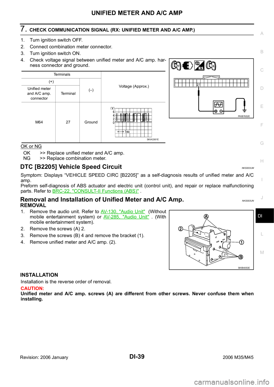
7. CHECK COMMUNICATION SIGNAL (RX: UNIFIED METER AND A/C AMP.)
1. Turn ignition switch OFF.
2. Connect combination meter connector.
3. Turn ignition switch ON.
4. Check voltage signal between unified meter and A/C amp. har-
ness connector and ground.
OK or NG
OK >> Replace unified meter and A/C amp.
NG >> Replace combination meter.
DTC [B2205] Vehicle Speed CircuitNKS003UM
Symptom: Displays “VEHICLE SPEED CIRC [B2205]” as a self-diagnosis results of unified meter and A/C
amp.
Preform self-diagnosis of ABS actuator and electric unit (control unit), and repair or replace malfunctioning
parts. Refer to BRC-22, "
CONSULT-II Functions (ABS)" .
Removal and Installation of Unified Meter and A/C Amp. NKS003UN
REMOVAL
1. Remove the audio unit. Refer to AV- 1 3 0 , "Audio Unit" (Without
mobile entertainment system) or AV- 2 8 5 , "
Audio Unit" . (With
mobile entertainment system).
2. Remove the screws (A) 2.
3. Remove the screws (B) 4 and remove the bracket (1).
4. Remove unified meter and A/C amp. (2).
INSTALLATION
Installation is the reverse order of removal.
CAUTION:
Unified meter and A/C amp. screws (A) are different from other screws. Never confuse them when
installing.
Terminals
Voltage (Approx.) (+)
(–) Unified meter
and A/C amp.
connectorTerminal
M64 27 Ground
PKIB7652E
SKIA3361E
SKIB4053E
Page 1473 of 5621
DI-40
WARNING LAMPS
Revision: 2006 January2006 M35/M45
WARNING LAMPSPFP:24814
System DescriptionNKS003UO
OIL PRESSURE WARNING LAMP
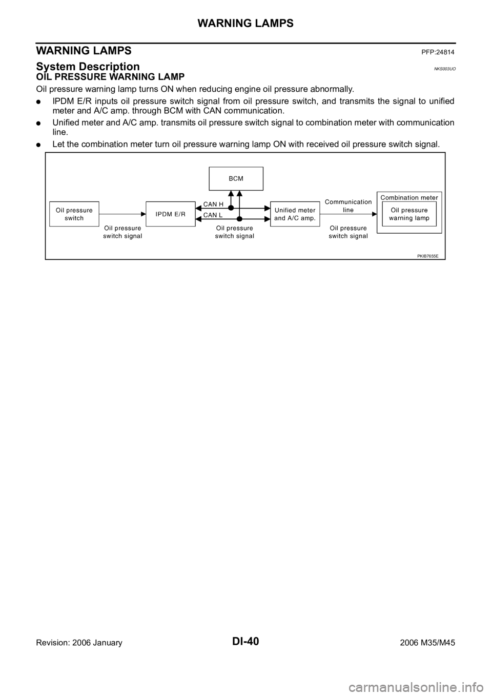
Oil pressure warning lamp turns ON when reducing engine oil pressure abnormally.
IPDM E/R inputs oil pressure switch signal from oil pressure switch, and transmits the signal to unified
meter and A/C amp. through BCM with CAN communication.
Unified meter and A/C amp. transmits oil pressure switch signal to combination meter with communication
line.
Let the combination meter turn oil pressure warning lamp ON with received oil pressure switch signal.
PKIB7655E
Page 1486 of 5621
WARNING LAMPS
DI-53
C
D
E
F
G
H
I
J
L
MA
B
DI
Revision: 2006 January2006 M35/M45
Oil Pressure Warning Lamp Stays Off (Ignition Switch ON)NKS003US
1. CHECK OPERATION OF OIL PRESSURE WARNING LAMP
Activate IPDM E/R auto active test. Refer to PG-24, "
Auto Active Test" .
Does oil pressure warning lamp is blinking?
YES >> GO TO 2.
NO >> GO TO 4.
2. CHECK OIL PRESSURE SWITCH CIRCUIT
1. Turn ignition switch OFF.
2. Disconnect IPDM E/R connector and oil pressure switch con-
nector.
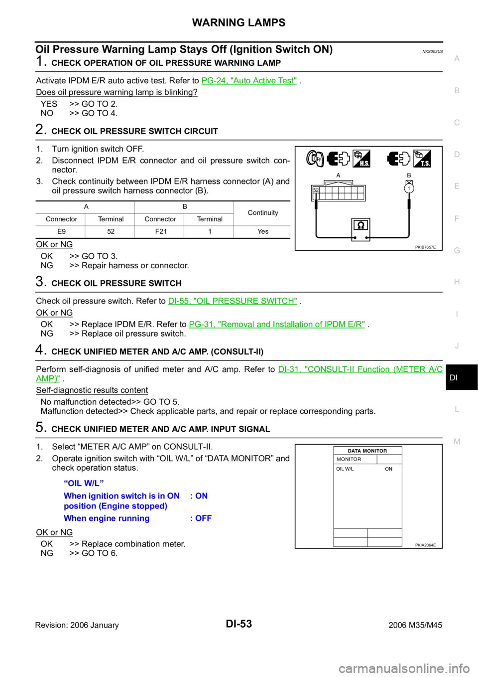
3. Check continuity between IPDM E/R harness connector (A) and
oil pressure switch harness connector (B).
OK or NG
OK >> GO TO 3.
NG >> Repair harness or connector.
3. CHECK OIL PRESSURE SWITCH
Check oil pressure switch. Refer to DI-55, "
OIL PRESSURE SWITCH" .
OK or NG
OK >> Replace IPDM E/R. Refer to PG-31, "Removal and Installation of IPDM E/R" .
NG >> Replace oil pressure switch.
4. CHECK UNIFIED METER AND A/C AMP. (CONSULT-II)
Perform self-diagnosis of unified meter and A/C amp. Refer to DI-31, "
CONSULT-II Function (METER A/C
AMP)" .
Self
-diagnostic results content
No malfunction detected>> GO TO 5.
Malfunction detected>> Check applicable parts, and repair or replace corresponding parts.
5. CHECK UNIFIED METER AND A/C AMP. INPUT SIGNAL
1. Select “METER A/C AMP” on CONSULT-II.
2. Operate ignition switch with “OIL W/L” of “DATA MONITOR” and
check operation status.
OK or NG
OK >> Replace combination meter.
NG >> GO TO 6.
AB
Continuity
Connector Terminal Connector Terminal
E9 52 F21 1 Yes
PKIB7657E
“OIL W/L”
When ignition switch is in ON
position (Engine stopped): ON
When engine running : OFF
PKIA2064E
Page 1487 of 5621
DI-54
WARNING LAMPS
Revision: 2006 January2006 M35/M45
6. CHECK BCM INPUT SIGNAL
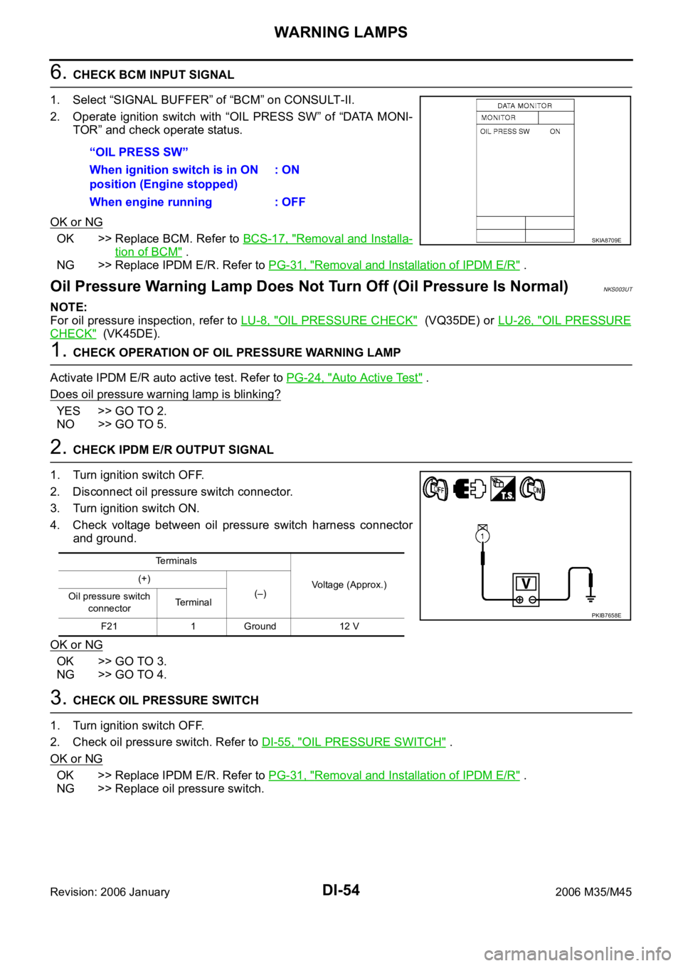
1. Select “SIGNAL BUFFER” of “BCM” on CONSULT-II.
2. Operate ignition switch with “OIL PRESS SW” of “DATA MONI-
TOR” and check operate status.
OK or NG
OK >> Replace BCM. Refer to BCS-17, "Removal and Installa-
tion of BCM" .
NG >> Replace IPDM E/R. Refer to PG-31, "
Removal and Installation of IPDM E/R" .
Oil Pressure Warning Lamp Does Not Turn Off (Oil Pressure Is Normal)NKS003UT
NOTE:
For oil pressure inspection, refer to LU-8, "
OIL PRESSURE CHECK" (VQ35DE) or LU-26, "OIL PRESSURE
CHECK" (VK45DE).
1. CHECK OPERATION OF OIL PRESSURE WARNING LAMP
Activate IPDM E/R auto active test. Refer to PG-24, "
Auto Active Test" .
Does oil pressure warning lamp is blinking?
YES >> GO TO 2.
NO >> GO TO 5.
2. CHECK IPDM E/R OUTPUT SIGNAL
1. Turn ignition switch OFF.
2. Disconnect oil pressure switch connector.
3. Turn ignition switch ON.
4. Check voltage between oil pressure switch harness connector
and ground.
OK or NG
OK >> GO TO 3.
NG >> GO TO 4.
3. CHECK OIL PRESSURE SWITCH
1. Turn ignition switch OFF.
2. Check oil pressure switch. Refer to DI-55, "
OIL PRESSURE SWITCH" .
OK or NG
OK >> Replace IPDM E/R. Refer to PG-31, "Removal and Installation of IPDM E/R" .
NG >> Replace oil pressure switch.“OIL PRESS SW”
When ignition switch is in ON
position (Engine stopped): ON
When engine running : OFF
SKIA8709E
Terminals
Voltage (Approx.) (+)
(–)
Oil pressure switch
connectorTe r m i n a l
F21 1 Ground 12 V
PKIB7658E
Page 1494 of 5621

WARNING CHIME
DI-61
C
D
E
F
G
H
I
J
L
MA
B
DI
Revision: 2006 January2006 M35/M45
IGNITION KEY WARNING CHIME (WITH INTELLIGENT KEY)
Refer to BL-55, "WARNING FUNCTION" in intelligent key system.
LIGHT WARNING CHIME
With ignition switch in OFF or ACC position, driver door open, and lighting switch in 1ST or 2ND position, the
light warning chime will sound.
BCM detects ignition switch in OFF or ACC position, front door switch (driver side) ON, and lighting switch
in 1ST or 2ND position. And then transmits buzzer output signal (light warning chime) to unified meter and
A/C amp. with CAN communication line.
Unified meter and A/C amp. transmits buzzer output signal (light warning chime) to combination meter
with communication line.
When combination meter receives buzzer output signal (light warning chime), it sounds the buzzer.
NOTE:
For further details of combination switch, refer to BCS-3, "
COMBINATION SWITCH READING FUNCTION" .
SEAT BELT WARNING CHIME
With ignition switch turned ON and driver seat belt unfastened, seat belt warning chime will sound for approxi-
mately 6 seconds.
BCM receives seat belt buckle switch signal [seat belt buckle switch (driver side) ON] from unified meter
and A/C amp. with CAN communication line.
BCM detects ignition switch turned ON and seat belt buckle switch (driver side) ON. And then transmits
buzzer output signal (seat belt warning chime) to unified meter and A/C amp. with CAN communication
line.
Unified meter and A/C amp. transmits buzzer output signal (seat belt warning chime) to combination
meter with communication line.
When combination meter receives buzzer output signal (seat belt warning chime), it sounds the buzzer.
SKIB3858E
SKIB3859E
Page 1502 of 5621
WARNING CHIME
DI-69
C
D
E
F
G
H
I
J
L
MA
B
DI
Revision: 2006 January2006 M35/M45
CONSULT-II Function (BCM)NKS003V5
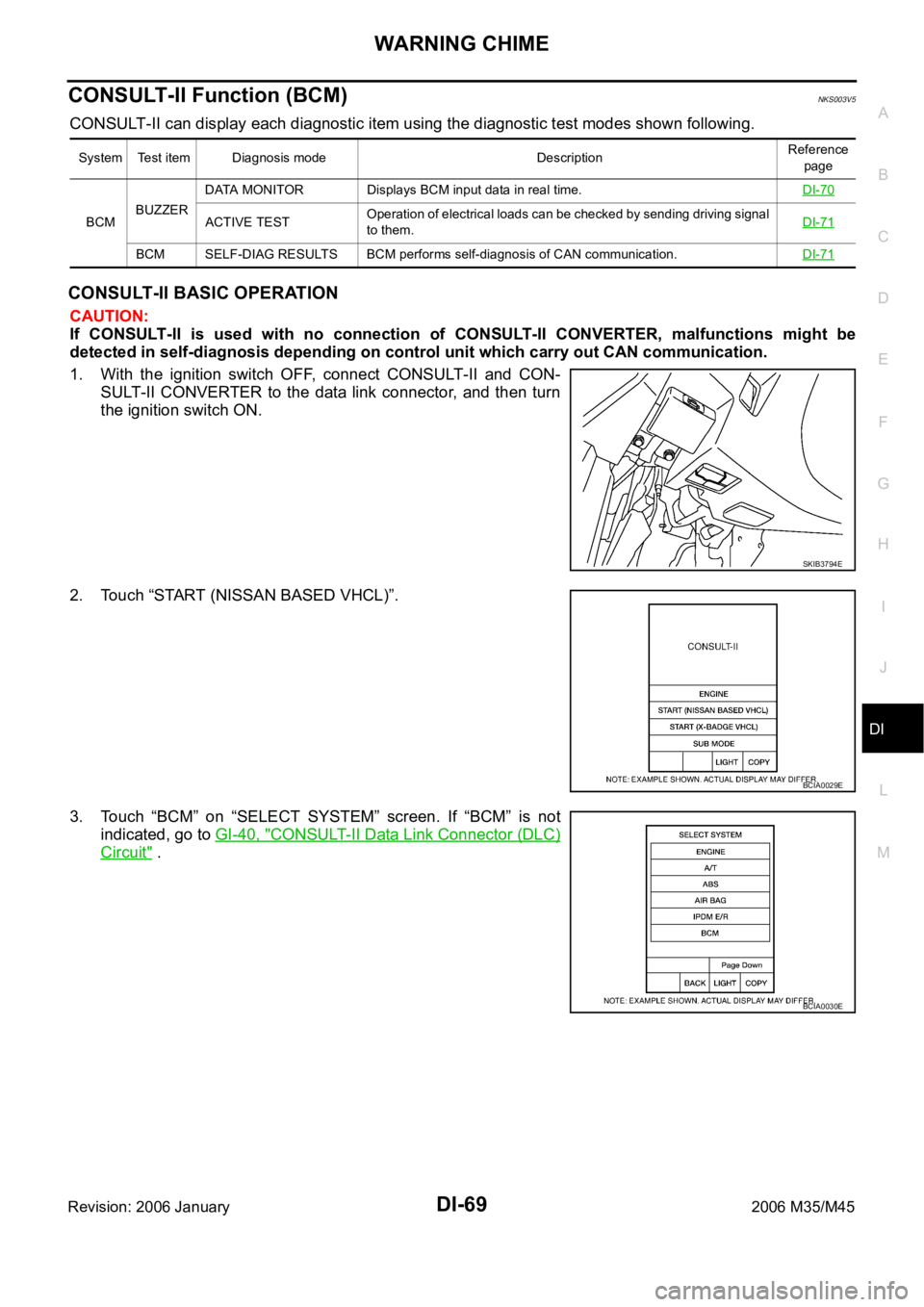
CONSULT-II can display each diagnostic item using the diagnostic test modes shown following.
CONSULT-II BASIC OPERATION
CAUTION:
If CONSULT-II is used with no connection of CONSULT-II CONVERTER, malfunctions might be
detected in self-diagnosis depending on control unit which carry out CAN communication.
1. With the ignition switch OFF, connect CONSULT-II and CON-
SULT-II CONVERTER to the data link connector, and then turn
the ignition switch ON.
2. Touch “START (NISSAN BASED VHCL)”.
3. Touch “BCM” on “SELECT SYSTEM” screen. If “BCM” is not
indicated, go to GI-40, "
CONSULT-II Data Link Connector (DLC)
Circuit" .
System Test item Diagnosis mode DescriptionReference
page
BCMBUZZERDATA MONITOR Displays BCM input data in real time.DI-70
ACTIVE TESTOperation of electrical loads can be checked by sending driving signal
to them.DI-71
BCM SELF-DIAG RESULTS BCM performs self-diagnosis of CAN communication.DI-71
SKIB3794E
BCIA0029E
BCIA0030E
Page 1505 of 5621
DI-72
WARNING CHIME
Revision: 2006 January2006 M35/M45
2. CHECK UNIFIED METER AND A/C AMP. (CONSULT-II)
Perform self-diagnosis of unified meter and A/C amp. Refer to DI-71, "
CONSULT-II Function (METER A/C
AMP)" .
Self
-diagnostic results content
No malfunction detected>> INSPECTION END
Malfunction detected>> Check applicable parts, and repair or replace corresponding parts.
SYMPTOM CHART
Meter Buzzer Circuit InspectionNKS003V8
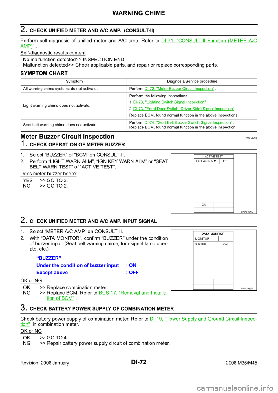
1. CHECK OPERATION OF METER BUZZER
1. Select “BUZZER” of “BCM” on CONSULT-II.
2. Perform “LIGHT WARN ALM”, “IGN KEY WARN ALM” or “SEAT
BELT WARN TEST” of “ACTIVE TEST”.
Does meter buzzer beep?
YES >> GO TO 3.
NO >> GO TO 2.
2. CHECK UNIFIED METER AND A/C AMP. INPUT SIGNAL
1. Select “METER A/C AMP” on CONSULT-II.
2. With “DATA MONITOR”, confirm “BUZZER” under the condition
of buzzer input. (Seat belt warning chime, turn signal lamp oper-
ate, etc.)
OK or NG
OK >> Replace combination meter.
NG >> Replace BCM. Refer to BCS-17, "
Removal and Installa-
tion of BCM" .
3. CHECK BATTERY POWER SUPPLY OF COMBINATION METER
Check battery power supply of combination meter. Refer to DI-19, "
Power Supply and Ground Circuit Inspec-
tion" in combination meter.
OK or NG
OK >> GO TO 4.
NG >> Repair battery power supply circuit of combination meter.
Symptom Diagnosis/Service procedure
All warning chime systems do not activate. Perform DI-72, "
Meter Buzzer Circuit Inspection" .
Light warning chime does not activate.Perform the following inspections.
1.DI-73, "
Lighting Switch Signal Inspection"
2.DI-73, "Front Door Switch (Driver Side) Signal Inspection"
Replace BCM, found normal function in the above inspections.
Seat belt warning chime does not activate.Perform DI-74, "
Seat Belt Buckle Switch Signal Inspection" .
Replace BCM, found normal function in the above inspection.
SKIA6331E
“BUZZER”
Under the condition of buzzer input : ON
Except above : OFF
PKIA2063E
Page 1506 of 5621
WARNING CHIME
DI-73
C
D
E
F
G
H
I
J
L
MA
B
DI
Revision: 2006 January2006 M35/M45
4. CHECK BATTERY POWER SUPPLY OF UNIFIED METER AND A/C AMP.
Check battery power supply of unified meter and A/C amp. Refer to DI-35, "
Power Supply and Ground Circuit
Inspection" in unified meter and A/C amp.
OK or NG
OK >> Replace BCM. Refer to BCS-17, "Removal and Installation of BCM" .
NG >> Repair battery power supply circuit of unified meter and A/C amp.
Lighting Switch Signal InspectionNKS003V9
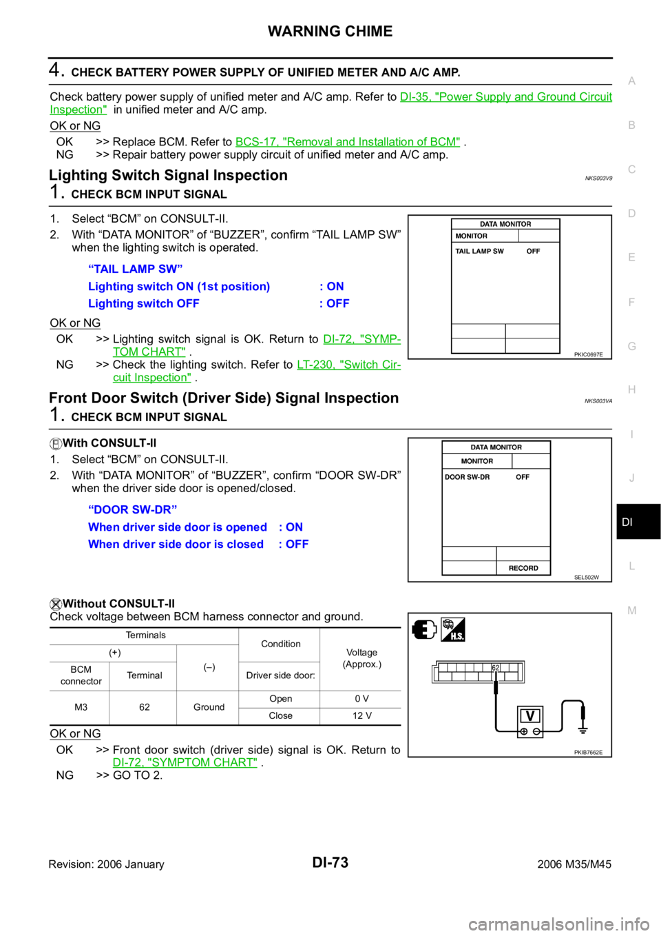
1. CHECK BCM INPUT SIGNAL
1. Select “BCM” on CONSULT-II.
2. With “DATA MONITOR” of “BUZZER”, confirm “TAIL LAMP SW”
when the lighting switch is operated.
OK or NG
OK >> Lighting switch signal is OK. Return to DI-72, "SYMP-
TOM CHART" .
NG >> Check the lighting switch. Refer to LT- 2 3 0 , "
Switch Cir-
cuit Inspection" .
Front Door Switch (Driver Side) Signal InspectionNKS003VA
1. CHECK BCM INPUT SIGNAL
With CONSULT-ll
1. Select “BCM” on CONSULT-II.
2. With “DATA MONITOR” of “BUZZER”, confirm “DOOR SW-DR”
when the driver side door is opened/closed.
Without CONSULT-ll
Check voltage between BCM harness connector and ground.
OK or NG
OK >> Front door switch (driver side) signal is OK. Return to
DI-72, "
SYMPTOM CHART" .
NG >> GO TO 2.“TAIL LAMP SW”
Lighting switch ON (1st position) : ON
Lighting switch OFF : OFF
PKIC0697E
“DOOR SW-DR”
When driver side door is opened : ON
When driver side door is closed : OFF
SEL502W
Terminals
Condition
Voltage
(Approx.) (+)
(–)
BCM
connectorTerminal Driver side door:
M3 62 GroundOpen 0 V
Close 12 V
PKIB7662E