Page 1172 of 5621
VEHICLE SECURITY (THEFT WARNING) SYSTEM
BL-233
C
D
E
F
G
H
J
K
L
MA
B
BL
Revision: 2006 January2006 M35/M45
CONSULT-II Function (BCM)NIS00201
CONSULT-II can display each diagnostic item using the diagnostic test modes shown following.
CAUTION:
CONSULT-II is used with no connection of CONSULT-II CONVERTER, malfunction might be detected in
self-diagnosis depending on control units with carry out CAN communication.
1. Turn ignition switch OFF.
2. Connect CONSULT-II and CONSULT-II CONVERTER to data
link connector (1).
3. Turn ignition switch ON.
4. Touch “START” (NISSAN BASED VHCL).
5. Touch “BCM”.
If “BCM” is not indicated, go to GI-40, "
CONSULT-II Data Link
Connector (DLC) Circuit" .
BCM diagnosis
positionInspection items and diagnosis mode Description
THEFT ALMDATA MONITOR Displays the input data to BCM in real time basis.
ACTIVE TEST Gives a drive signal to a load to check the operation.
WORK SUPPORT Changes setting of each function.
PBIB2712E
BCIA0029E
BCIA0030E
Page 1174 of 5621

VEHICLE SECURITY (THEFT WARNING) SYSTEM
BL-235
C
D
E
F
G
H
J
K
L
MA
B
BL
Revision: 2006 January2006 M35/M45
Active Test
Trouble Diagnosis Work FlowNIS00202
1. CHECK IN
Listen to customer complaint.
>> GO TO 2.
2. CHECK FUNCTION
Do “Power door lock system” and “Intelligent Key system” work properly?
YES >> GO TO 3.
NO >> Preform diagnosis and repair. Refer to .
3. PERFORM DIAGNOSTIC PROCEDURE
Perform diagnostic procedure according to the symptom chart. Refer to BL-237, "
Trouble Diagnosis Symptom
Chart" .
>> GO TO 4.
4. FINAL CHECK
Confirm that the malfunction is completely fixed by operating the system.
OK >> INSPECTION END
NG >> GO TO 3.
Preliminary CheckNIS00203
1. INSPECTION START
Turn ignition switch "OFF" and pull out Intelligent Key from key slot.
NOTE:
Before starting operation check, open front windows.
>> GO TO 2.
CDL LOCK SW Indicates [ON/OFF] condition of lock signal from door lock/unlock switch LH and RH.
CDL UNLOCK SW Indicates [ON/OFF] condition of unlock signal from door lock/unlock switch LH and RH. Monitored Item Description
Test Item Description
THEFT INDThis test is able to check security indicator lamp operation. The lamp will be turned on when “ON”
on CONSULT-II screen is touched.
VEHICLE SECURITY HORNThis test is able to check vehicle security horn operation. The horns will be activated for 0.5 sec-
onds after “ON” on CONSULT-II screen is touched.
HEADLAMP(HI)This test is able to check vehicle security lamp operation. The headlamps will be activated for 0.5
seconds after “ON” on CONSULT-II screen is touched.
FLASHERThis test is able to check vehicle security hazard lamp operation. The hazard lamps will be acti-
vated after “ON” on CONSULT-II screen is touched.
Page 1177 of 5621
BL-238
VEHICLE SECURITY (THEFT WARNING) SYSTEM
Revision: 2006 January2006 M35/M45
Diagnostic Procedure 1NIS00205
DOOR SWITCH CHECK
1. CHECK DOOR SWITCH INPUT SIGNAL
With CONSULT-II
Check door switches (“DOOR SW-DR”, “DOOR SW-AS”, “DOOR SW-RL” and “DOOR SW-RR”) in “DATA
MONITOR” mode with CONSULT-II.
Without CONSULT-II
1. Turn ignition switch OFF.
2. Check voltage between BCM connector and ground.
OK or NG
OK >> Door switch circuit is OK.
NG >> GO TO 2.
Monitor item Condition
DOOR SW-DR
CLOSE
OPEN: OFF ON DOOR SW-AS
DOOR SW-RL
DOOR SW-RR
PIIA6469E
Terminals
Door conditionVoltage (V)
(Approx.) (+)
(–)
BCM
connectorTerminal
M112
GroundFront
passenger
sideOPEN 0
CLOSE Battery voltage
13Rear RH
sideOPEN 0
CLOSE Battery voltage
M362 Driver sideOPEN 0
CLOSE Battery voltage
63Rear LH
sideOPEN 0
CLOSE Battery voltage
PIIB6324E
Page 1180 of 5621

VEHICLE SECURITY (THEFT WARNING) SYSTEM
BL-241
C
D
E
F
G
H
J
K
L
MA
B
BL
Revision: 2006 January2006 M35/M45
HOOD SWITCH CHECK
1. CHECK HOOD SWITCH
Check hood switch and hood fitting condition.
OK or NG
OK >> GO TO 2.
NG >> Adjust installation of hood switch.
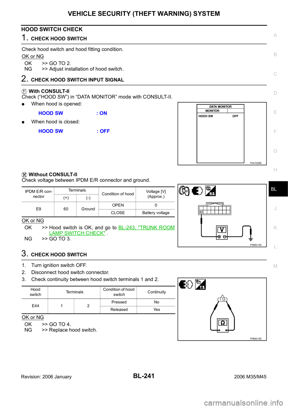
2. CHECK HOOD SWITCH INPUT SIGNAL
With CONSULT-II
Check (“HOOD SW”) in “DATA MONITOR” mode with CONSULT-II.
When hood is opened:
When hood is closed:
Without CONSULT-II
Check voltage between IPDM E/R connector and ground.
OK or NG
OK >> Hood switch is OK, and go to BL-243, "TRUNK ROOM
LAMP SWITCH CHECK" .
NG >> GO TO 3.
3. CHECK HOOD SWITCH
1. Turn ignition switch OFF.
2. Disconnect hood switch connector.
3. Check continuity between hood switch terminals 1 and 2.
OK or NG
OK >> GO TO 4.
NG >> Replace hood switch.HOOD SW : ON
HOOD SW : OFF
PIIA7006E
IPDM E/R con-
nectorTe r m i n a l s
Condition of hoodVoltage [V]
(Approx.)
(+) (-)
E9 60 GroundOPEN 0
CLOSE Battery voltage
PIIB6214E
Hood
switchTerminalsCondition of hood
switchContinuity
E44 1 2Pressed No
Released Yes
PIIB6215E
Page 1182 of 5621
VEHICLE SECURITY (THEFT WARNING) SYSTEM
BL-243
C
D
E
F
G
H
J
K
L
MA
B
BL
Revision: 2006 January2006 M35/M45
TRUNK ROOM LAMP SWITCH CHECK
1. CHECK TRUNK ROOM LAMP SWITCH INPUT SIGNAL
With CONSULT-II
Check (“TRUNK SW”) in “DATA MONITOR” mode with CONSULT-II.
Without CONSULT-II
1. Turn ignition switch OFF.
2. Check voltage between BCM connector and ground.
OK or NG
OK >> Trunk room lamp switch circuit is OK.
NG >> GO TO 2.
2. CHECK TRUNK ROOM LAMP SWITCH
1. Turn ignition switch OFF.
2. Disconnect trunk lid lock assembly connector.
3. Check trunk room lamp switch.
OK or NG
OK >> GO TO 3.
NG >> Replace trunk room lamp switch.
Monitor item Condition
TRUNK SWOPEN : ON
CLOSE : OFF
PIIB1362E
Terminals
Trunk
conditionVoltage (V)
(Approx.) (+)
(–)
BCM connector Terminal
M3 57 GroundOPEN 0
CLOSE Battery voltage
PIIB6326E
Terminal
Trunk condition Continuity
Trunk room lamp switch
12OPEN Yes
CLOSE No
PIIB6327E
Page 1185 of 5621

BL-246
VEHICLE SECURITY (THEFT WARNING) SYSTEM
Revision: 2006 January2006 M35/M45
Diagnostic Procedure 3NIS00207
FRONT DOOR KEY CYLINDER SWITCH CHECK
1. CHECK KEY CYLINDER SWITCH OPERATION
Check if door key cylinder switch using mechanical key.
Do doors lock / unlock when using the mechanical key?
YES >> Front door key cylinder switch operation is OK.
NO >> Check door key cylinder switch circuit. Refer to BL-42, "
Door Key Cylinder Switch Check" .
Diagnostic Procedure 4NIS00208
VEHICLE SECURITY HORN ALARM CHECK
First perform the “SELF-DIAG RESULTS” of “BCM” with CONSULT-II, then perform the trouble diagno-
sis of malfunction system indicated in “SELF-DIAG RESULTS” of “BCM”. Refer to BCS-15, "
CAN Com-
munication Inspection Using CONSULT-II (Self-Diagnosis)".
1. CHECK HORN OPERATION
Check if horn sounds with horn switch.
Does horn operate?
Yes >> GO TO 2.
No >> Check horn circuit. Refer to WW-53, "
HORN" .
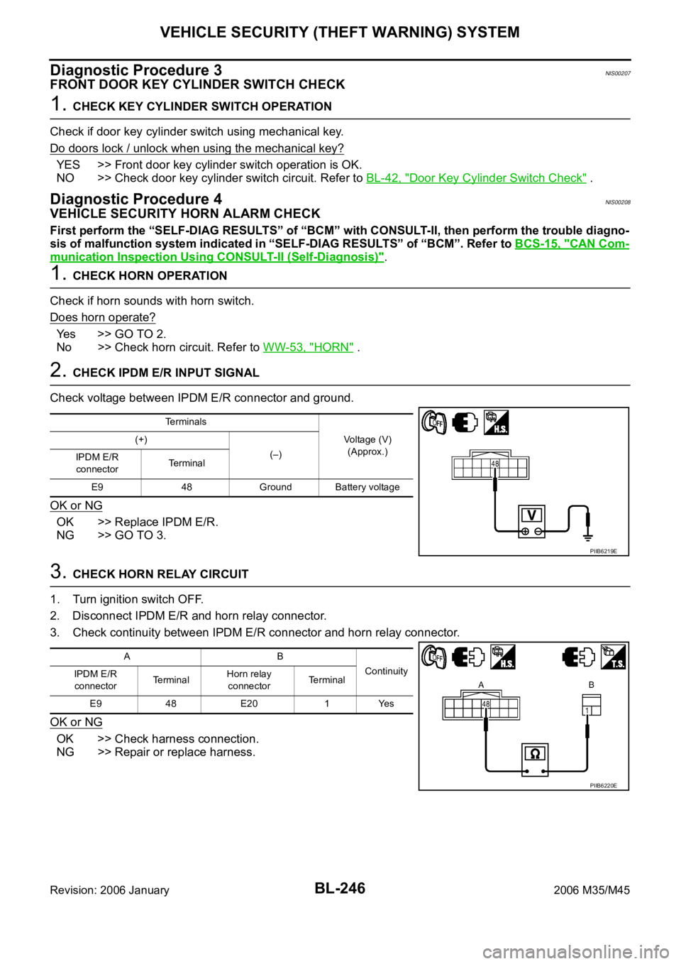
2. CHECK IPDM E/R INPUT SIGNAL
Check voltage between IPDM E/R connector and ground.
OK or NG
OK >> Replace IPDM E/R.
NG >> GO TO 3.
3. CHECK HORN RELAY CIRCUIT
1. Turn ignition switch OFF.
2. Disconnect IPDM E/R and horn relay connector.
3. Check continuity between IPDM E/R connector and horn relay connector.
OK or NG
OK >> Check harness connection.
NG >> Repair or replace harness.
Terminals
Voltage (V)
(Approx.) (+)
(–)
IPDM E/R
connectorTerminal
E9 48 Ground Battery voltage
PIIB6219E
AB
Continuity
IPDM E/R
connectorTe r m i n a lHorn relay
connectorTerminal
E9 48 E20 1 Yes
PIIB6220E
Page 1186 of 5621

VEHICLE SECURITY (THEFT WARNING) SYSTEM
BL-247
C
D
E
F
G
H
J
K
L
MA
B
BL
Revision: 2006 January2006 M35/M45
Diagnostic Procedure 5NIS00209
VEHICLE SECURITY HEADLAMP ALARM CHECK
1. CHECK HEADLAMP OPERATION
Check if headlamp operate by lighting switch.
Does headlamp come on when turning switch
“ON”?
YES >> Headlamp circuit is OK.
NO >> Check headlamp system. Refer to LT- 4 3 , "
HEADLAMP (FOR USA) - XENON TYPE -" , LT- 8 ,
"HEADLAMP (FOR USA) - CONVENTIONAL TYPE -" or LT- 7 9 , "HEADLAMP (FOR CANADA) -
DAYTIME LIGHT SYSTEM -" .
Diagnostic Procedure 6NIS0020A
DOOR LOCK AND UNLOCK SWITCH CHECK
1. CHECK DOOR LOCK AND UNLOCK SWITCH INPUT SIGNAL
Check if power door lock operated by door lock and unlock switch.
Do doors lock / unlock when using each door lock and unlock switches?
YES >> Door lock and unlock switch is OK.
NO >> Check door lock and unlock switch. Refer to BL-36, "
Check Door Lock and Unlock Switch"
Diagnostic Procedure 7NIS0020B
VEHCLE SECURITY HAZARD LAMP ALARM CHECK
1. CHECK HAZARD WARNING LAMP
Does hazard warning lamp flash with hazard switch?
YES or NO
YES >> Hazard warning lamp circuit is OK.
NO >> Check hazard circuit. Refer to LT- 2 11 , "
TURN SIGNAL AND HAZARD WARNING LAMPS" .
Page 1190 of 5621

IVIS (INFINITI VEHICLE IMMOBILIZER SYSTEM-NATS)
BL-251
C
D
E
F
G
H
J
K
L
MA
B
BL
Revision: 2006 January2006 M35/M45
Operation DescriptionNIS0020E
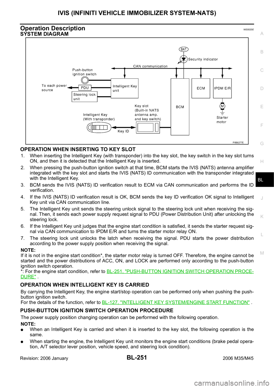
SYSTEM DIAGRAM
OPERATION WHEN INSERTING TO KEY SLOT
1. When inserting the Intelligent Key (with transponder) into the key slot, the key switch in the key slot turns
ON, and then it is detected that the Intelligent Key is inserted.
2. When pressing the push-button ignition switch at that time, BCM starts the IVIS (NATS) antenna amplifier
integrated with the key slot and starts the IVIS (NATS) ID communication with the transponder integrated
with the Intelligent Key.
3. BCM sends the IVIS (NATS) ID verification result to ECM via CAN communication and performs the ID
verification.
4. If the IVIS (NATS) ID verification result is OK, BCM sends the key ID verification OK signal to Intelligent
Key unit via CAN communication line.
5. The Intelligent Key unit sends the steering unlock signal to the steering lock unit when receiving the sig-
nal. Then, it sends each power supply request signal to PDU (Power Distribution Unit) after unlocking the
steering lock.
6. If the Intelligent Key unit judges that the engine start condition is satisfied, it sends the starter request sig-
nal via CAN communication to IPDM E/R and turns the starter motor relay ON.
7. The steering lock unit unlocks the latch when receiving the signal. PDU starts the power distribution
according to the power supply position when receiving the signal.
NOTE:
If it is not in the engine start condition*, the starter motor relay is turned OFF. Therefore, the engine cannot be
started and the power distributions of ACC, ON, and LOCK are performed only according to the push-button
ignition switch operation.
*: For the engine start condition, refer to BL-251, "
PUSH-BUTTON IGNITION SWITCH OPERATION PROCE-
DURE" .
OPERATION WHEN INTELLIGENT KEY IS CARRIED
By carrying the Intelligent Key, the engine start/stop operation can be performed only when pushing the push-
button ignition switch.
For the details of the function, refer to BL-127, "
INTELLIGENT KEY SYSTEM/ENGINE START FUNCTION" .
PUSH-BUTTON IGNITION SWITCH OPERATION PROCEDURE
The power supply position changing operation can be performed with the following operation.
NOTE:
When an Intelligent Key is carried and when it is inserted to the key slot, the following operation is the
same.
When starting the engine, the Intelligent Key unit monitors the engine start conditions (brake pedal opera-
tion, A/T selector lever position, vehicle speed, and steering lock condition).
PIIB6277E