Page 1019 of 5621

BL-80
INTELLIGENT KEY SYSTEM
Revision: 2006 January2006 M35/M45
15. CHECK OUT
CHECK OUT.
>> INSPECTION END
CONSULT-II Functions (INTELLIGENT KEY)NIS001XH
CONSULT-II can display each diagnostic item using the diagnostic test modes as shown below.
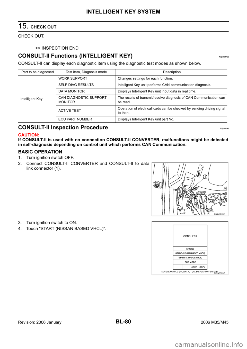
CONSULT-II Inspection ProcedureNIS001XI
CAUTION:
If CONSULT-II is used with no connection CONSULT-II CONVERTER, malfunctions might be detected
in self-diagnosis depending on control unit which performs CAN Communication.
BASIC OPERATION
1. Turn ignition switch OFF.
2. Connect CONSULT-II CONVERTER and CONSULT-II to data
link connector (1).
3. Turn ignition switch to ON.
4. Touch “START (NISSAN BASED VHCL)”.
Part to be diagnosed Test item, Diagnosis mode Description
Intelligent KeyWORK SUPPORT Changes settings for each function.
SELF-DIAG RESULTS Intelligent Key unit performs CAN communication diagnosis.
DATA MONITOR Displays Intelligent Key unit input data in real time.
CAN DIAGNOSTIC SUPPORT
MONITORThe results of transmit/receive diagnosis of CAN Communication can
be read.
ACTIVE TESTOperation of electrical loads can be checked by sending driving signal
to then.
ECU PART NUMBER Displays Intelligent Key unit part No.
PBIB2712E
BCIA0029E
Page 1033 of 5621
BL-94
INTELLIGENT KEY SYSTEM
Revision: 2006 January2006 M35/M45
Check Key SlotNIS001XN
1. CHECK KEY SLOT INPUT SIGNAL
Check voltage between Intelligent Key unit harness connector and ground.
OK or NG
OK >> Key slot is OK.
NG >> GO TO 2.
2. CHECK KEY SLOT POWER SUPPLY CIRCUIT
1. Turn ignition switch OFF.
2. Disconnect key slot connector.
3. Check voltage between slot connector and ground.
OK or NG
OK >> GO TO 3.
NG >> Repair or replace key slot power supply circuit.
3. CHECK KEY SLOT
Check key slot.
OK or NG
OK >> GO TO 4.
NG >> Replace key slot.
Terminals
ConditionVoltage (V)
(Approx.) (+)
(–)
Intelligent Key
unit connectorTerminal
M32 19 GroundIntelligent Key inserted Battery voltage
Intelligent Key removed 0
PIIB6319E
Terminals
Voltage (V)
(Approx.) (+)
(–)
Key slot connector Terminal
M14 1 Ground Battery voltage
PIIB6320E
Terminal
Condition Continuity
Key slot
13Intelligent Key inserted Yes
Intelligent Key removed No
PIIB6321E
Page 1035 of 5621
BL-96
INTELLIGENT KEY SYSTEM
Revision: 2006 January2006 M35/M45
Check Door SwitchNIS001XO
1. CHECK DOOR SWITCH INPUT SIGNAL
With CONSULT-II
Check door switches (“DOOR SW-DR”, “DOOR SW-AS”, “DOOR SW-RL” and “DOOR SW-RR”) in “DATA
MONITOR” mode with CONSULT-II.
Without CONSULT-II
1. Turn ignition switch OFF.
2. Check voltage between BCM connector and ground.
OK or NG
OK >> Door switch circuit is OK.
NG >> GO TO 2.
Monitor item Condition
DOOR SW-DR
CLOSE
OPEN: OFF ON DOOR SW-AS
DOOR SW-RL
DOOR SW-RR
PIIA6469E
Terminals
Door conditionVoltage (V)
(Approx.) (+)
(–)
BCM
connectorTerminal
M112
GroundFront
passenger
sideOPEN 0
CLOSE Battery voltage
13Rear RH
sideOPEN 0
CLOSE Battery voltage
M362 Driver sideOPEN 0
CLOSE Battery voltage
63Rear LH
sideOPEN 0
CLOSE Battery voltage
PIIB6324E
Page 1038 of 5621
INTELLIGENT KEY SYSTEM
BL-99
C
D
E
F
G
H
J
K
L
MA
B
BL
Revision: 2006 January2006 M35/M45
Check Trunk Room Lamp SwitchNIS001XP
1. CHECK TRUNK ROOM LAMP SWITCH INPUT SIGNAL
With CONSULT-II
Check (“TRUNK SW”) in “DATA MONITOR” mode with CONSULT-II.
Without CONSULT-II
1. Turn ignition switch OFF.
2. Check voltage between BCM connector and ground.
OK or NG
OK >> Trunk room lamp switch circuit is OK.
NG >> GO TO 2.
2. CHECK TRUNK ROOM LAMP SWITCH
1. Turn ignition switch OFF.
2. Disconnect trunk lid lock assembly connector.
3. Check trunk room lamp switch.
OK or NG
OK >> GO TO 3.
NG >> Replace trunk room lamp switch.
Monitor item Condition
TRUNK SWOPEN : ON
CLOSE : OFF
PIIB1362E
Terminals
Trunk
conditionVoltage (V)
(Approx.) (+)
(–)
BCM connector Terminal
M3 57 GroundOPEN 0
CLOSE Battery voltage
PIIB6326E
Terminal
Trunk condition Continuity
Trunk room lamp switch
12OPEN Yes
CLOSE No
PIIB6327E
Page 1042 of 5621

INTELLIGENT KEY SYSTEM
BL-103
C
D
E
F
G
H
J
K
L
MA
B
BL
Revision: 2006 January2006 M35/M45
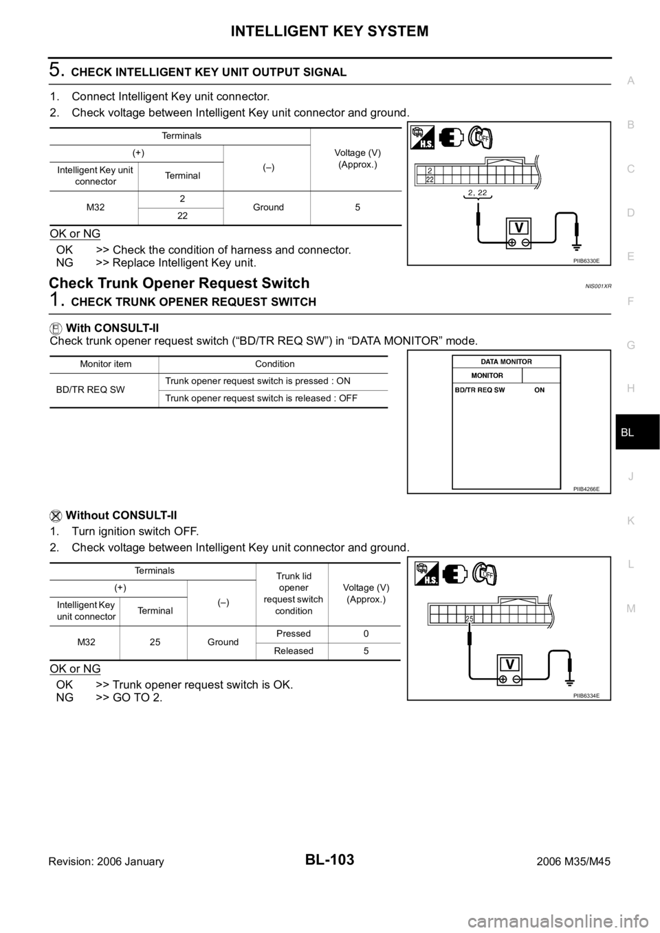
5. CHECK INTELLIGENT KEY UNIT OUTPUT SIGNAL
1. Connect Intelligent Key unit connector.
2. Check voltage between Intelligent Key unit connector and ground.
OK or NG
OK >> Check the condition of harness and connector.
NG >> Replace Intelligent Key unit.
Check Trunk Opener Request SwitchNIS001XR
1. CHECK TRUNK OPENER REQUEST SWITCH
With CONSULT-II
Check trunk opener request switch (“BD/TR REQ SW”) in “DATA MONITOR” mode.
Without CONSULT-II
1. Turn ignition switch OFF.
2. Check voltage between Intelligent Key unit connector and ground.
OK or NG
OK >> Trunk opener request switch is OK.
NG >> GO TO 2.
Terminals
Voltage (V)
(Approx.) (+)
(–)
Intelligent Key unit
connectorTerminal
M322
Ground 5
22
PIIB6330E
Monitor item Condition
BD/TR REQ SWTrunk opener request switch is pressed : ON
Trunk opener request switch is released : OFF
PIIB4266E
Terminals
Trunk lid
opener
request switch
conditionVoltage (V)
(Approx.) (+)
(–)
Intelligent Key
unit connectorTerminal
M32 25 GroundPressed 0
Released 5
PIIB6334E
Page 1045 of 5621

BL-106
INTELLIGENT KEY SYSTEM
Revision: 2006 January2006 M35/M45
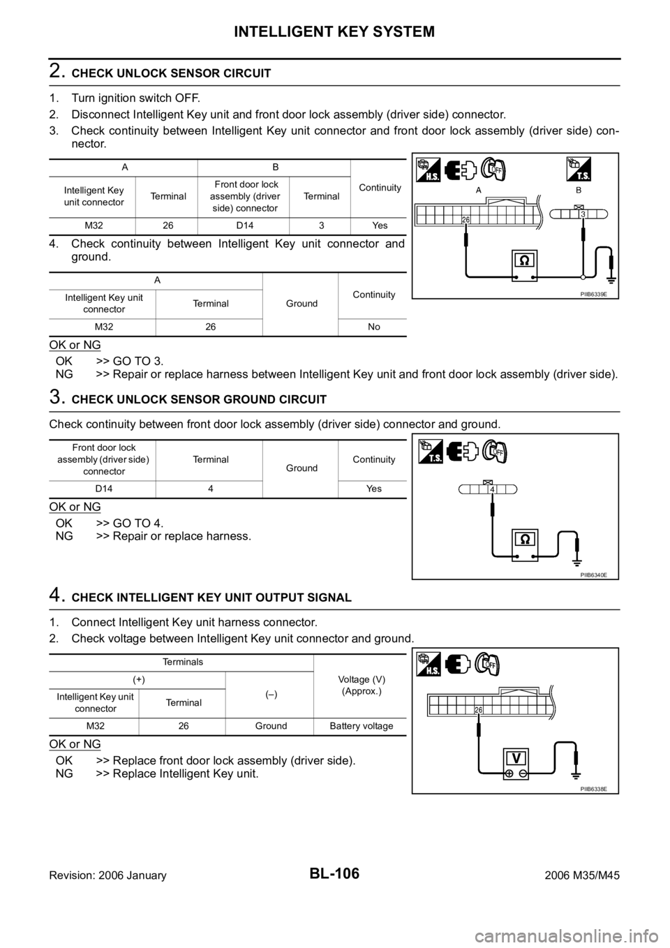
2. CHECK UNLOCK SENSOR CIRCUIT
1. Turn ignition switch OFF.
2. Disconnect Intelligent Key unit and front door lock assembly (driver side) connector.
3. Check continuity between Intelligent Key unit connector and front door lock assembly (driver side) con-
nector.
4. Check continuity between Intelligent Key unit connector and
ground.
OK or NG
OK >> GO TO 3.
NG >> Repair or replace harness between Intelligent Key unit and front door lock assembly (driver side).
3. CHECK UNLOCK SENSOR GROUND CIRCUIT
Check continuity between front door lock assembly (driver side) connector and ground.
OK or NG
OK >> GO TO 4.
NG >> Repair or replace harness.
4. CHECK INTELLIGENT KEY UNIT OUTPUT SIGNAL
1. Connect Intelligent Key unit harness connector.
2. Check voltage between Intelligent Key unit connector and ground.
OK or NG
OK >> Replace front door lock assembly (driver side).
NG >> Replace Intelligent Key unit.
AB
Continuity
Intelligent Key
unit connectorTe r m i n a l Front door lock
assembly (driver
side) connectorTerminal
M32 26 D14 3 Yes
A
GroundContinuity
Intelligent Key unit
connectorTerminal
M32 26 No
PIIB6339E
Front door lock
assembly (driver side)
connectorTerminal
GroundContinuity
D14 4 Yes
PIIB6340E
Terminals
Voltage (V)
(Approx.) (+)
(–)
Intelligent Key unit
connectorTerminal
M32 26 Ground Battery voltage
PIIB6338E
Page 1047 of 5621

BL-108
INTELLIGENT KEY SYSTEM
Revision: 2006 January2006 M35/M45
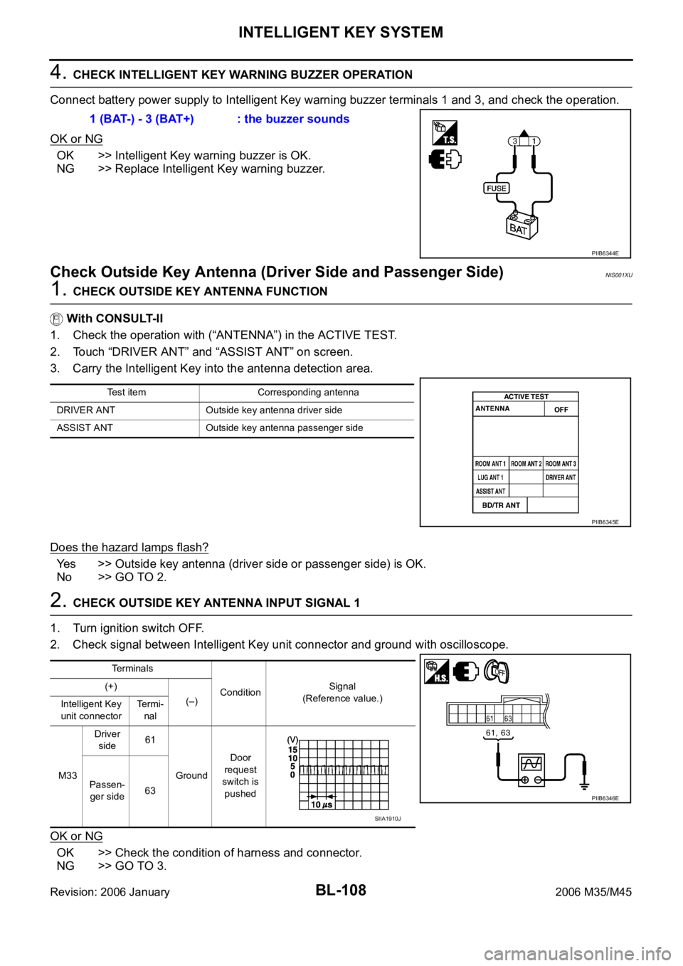
4. CHECK INTELLIGENT KEY WARNING BUZZER OPERATION
Connect battery power supply to Intelligent Key warning buzzer terminals 1 and 3, and check the operation.
OK or NG
OK >> Intelligent Key warning buzzer is OK.
NG >> Replace Intelligent Key warning buzzer.
Check Outside Key Antenna (Driver Side and Passenger Side)NIS001XU
1. CHECK OUTSIDE KEY ANTENNA FUNCTION
With CONSULT-II
1. Check the operation with (“ANTENNA”) in the ACTIVE TEST.
2. Touch “DRIVER ANT” and “ASSIST ANT” on screen.
3. Carry the Intelligent Key into the antenna detection area.
Does the hazard lamps flash?
Yes >> Outside key antenna (driver side or passenger side) is OK.
No >> GO TO 2.
2. CHECK OUTSIDE KEY ANTENNA INPUT SIGNAL 1
1. Turn ignition switch OFF.
2. Check signal between Intelligent Key unit connector and ground with oscilloscope.
OK or NG
OK >> Check the condition of harness and connector.
NG >> GO TO 3.1 (BAT-) - 3 (BAT+) : the buzzer sounds
PIIB6344E
Test item Corresponding antenna
DRIVER ANT Outside key antenna driver side
ASSIST ANT Outside key antenna passenger side
PIIB6345E
Te r m i n a l s
ConditionSignal
(Reference value.) (+)
(–)
Intelligent Key
unit connectorTermi-
nal
M33Driver
side61
GroundDoor
request
switch is
pushed Passen-
ger side63
PIIB6346E
SIIA1910J
Page 1049 of 5621
BL-110
INTELLIGENT KEY SYSTEM
Revision: 2006 January2006 M35/M45
Check Outside Key Antenna (Trunk Room)NIS001XV
1. CHECK OUTSIDE KEY ANTENNA FUNCTION
With CONSULT-II
1. Check the operation with (“ANTENNA”) in the ACTIVE TEST.
2. Touch “BD/TR ANT” on screen.
3. Carry the Intelligent Key into the antenna detection area.
Do the hazard lamps flash?
Yes >> Outside key antenna (trunk room) is OK.
No >> GO TO 2.
2. CHECK OUTSIDE KEY ANTENNA INPUT SIGNAL 1
1. Turn ignition switch OFF.
2. Check signal between Intelligent Key unit connector and ground with oscilloscope.
OK or NG
OK >> Check the condition of harness and connector.
NG >> GO TO 3.
Test item Corresponding antenna
BD/TR ANT Outside key antenna trunk room
PIIB6345E
Te r m i n a l s
ConditionSignal
(Reference value.) (+)
(–) Intelligent
Key unit
connectorTerminal
M33 69 GroundTrunk
request
switch is
pushed
PIIB6348E
SIIA1910J