Page 1113 of 5621
BL-174
INTELLIGENT KEY SYSTEM/ENGINE START FUNCTION
Revision: 2006 January2006 M35/M45
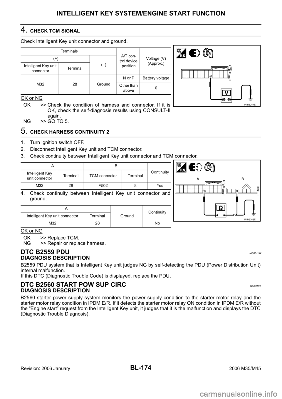
4. CHECK TCM SIGNAL
Check Intelligent Key unit connector and ground.
OK or NG
OK >> Check the condition of harness and connector. If it is
OK, check the self-diagnosis results using CONSULT-II
again.
NG >> GO TO 5.
5. CHECK HARNESS CONTINUITY 2
1. Turn ignition switch OFF.
2. Disconnect Intelligent Key unit and TCM connector.
3. Check continuity between Intelligent Key unit connector and TCM connector.
4. Check continuity between Intelligent Key unit connector and
ground.
OK or NG
OK >> Replace TCM.
NG >> Repair or replace harness.
DTC B2559 PDUNIS001YW
DIAGNOSIS DESCRIPTION
B2559 PDU system that is Intelligent Key unit judges NG by self-detecting the PDU (Power Distribution Unit)
internal malfunction.
If this DTC (Diagnostic Trouble Code) is displayed, replace the PDU.
DTC B2560 START POW SUP CIRCNIS001YX
DIAGNOSIS DESCRIPTION
B2560 starter power supply system monitors the power supply condition to the starter motor relay and the
starter motor relay condition in IPDM E/R. If it detects the starter motor relay ON condition in IPDM E/R without
the “Engine start” request from the Intelligent Key unit, it judges that it is the malfunction and displays the DTC
(Diagnostic Trouble Diagnosis).
Terminals
A/T con-
trol device
positionVoltage (V)
(Approx.) (+)
(–)
Intelligent Key unit
connectorTerminal
M32 28 GroundN or P Battery voltage
Other than
above0
PIIB6247E
AB
Continuity
Intelligent Key
unit connectorTerminal TCM connector Terminal
M32 28 F502 8 Yes
A
GroundContinuity
Intelligent Key unit connector Terminal
M32 28 No
PIIB6248E
Page 1122 of 5621
INTELLIGENT KEY SYSTEM/ENGINE START FUNCTION
BL-183
C
D
E
F
G
H
J
K
L
MA
B
BL
Revision: 2006 January2006 M35/M45
Check Inside Key AntennaNIS001Z5
1. CHECK INSIDE KEY ANTENNA FUNCTION
With CONSULT-II
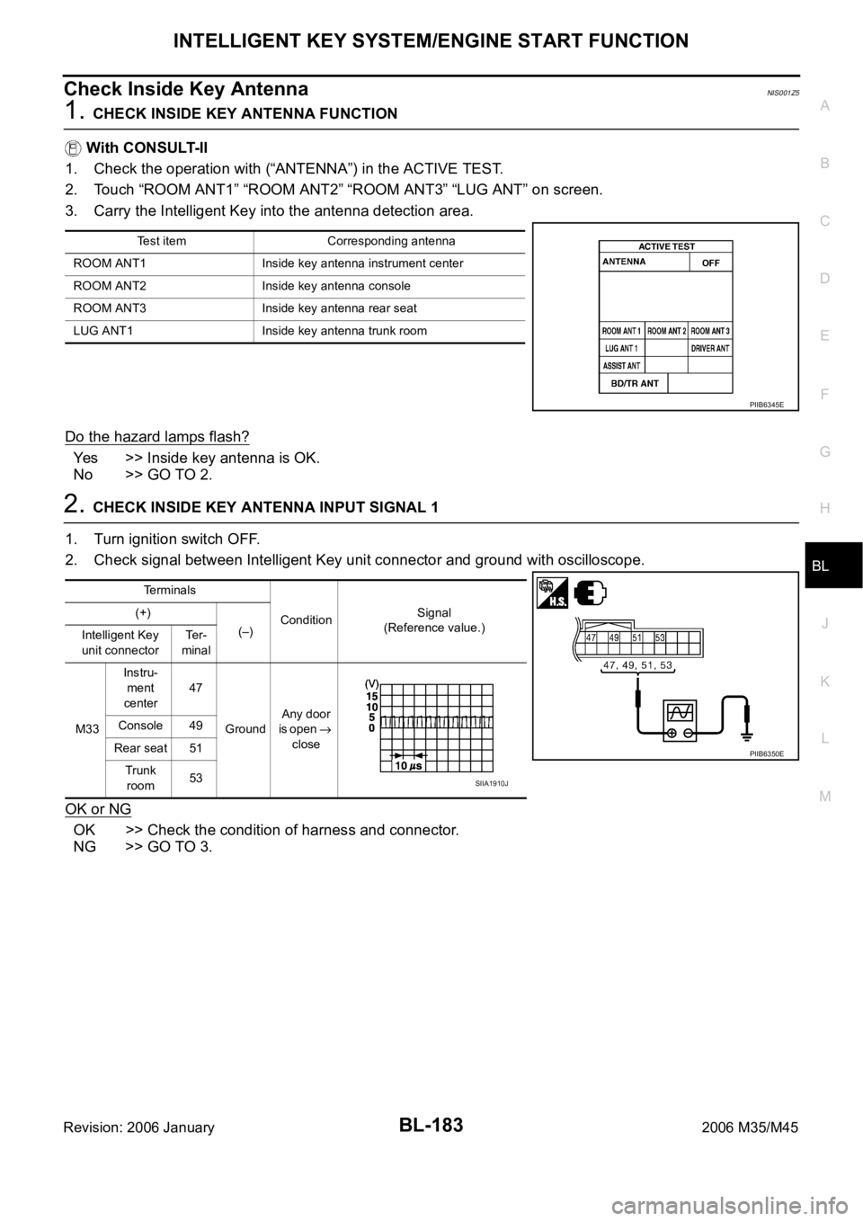
1. Check the operation with (“ANTENNA”) in the ACTIVE TEST.
2. Touch “ROOM ANT1” “ROOM ANT2” “ROOM ANT3” “LUG ANT” on screen.
3. Carry the Intelligent Key into the antenna detection area.
Do the hazard lamps flash?
Yes >> Inside key antenna is OK.
No >> GO TO 2.
2. CHECK INSIDE KEY ANTENNA INPUT SIGNAL 1
1. Turn ignition switch OFF.
2. Check signal between Intelligent Key unit connector and ground with oscilloscope.
OK or NG
OK >> Check the condition of harness and connector.
NG >> GO TO 3.
Test item Corresponding antenna
ROOM ANT1 Inside key antenna instrument center
ROOM ANT2 Inside key antenna console
ROOM ANT3 Inside key antenna rear seat
LUG ANT1 Inside key antenna trunk room
PIIB6345E
Terminals
ConditionSignal
(Reference value.) (+)
(–)
Intelligent Key
unit connectorTe r -
minal
M33Instru-
ment
center47
GroundAny door
is open
close Console 49
Rear seat 51
Trunk
room53
PIIB6350E
SIIA1910J
Page 1124 of 5621
INTELLIGENT KEY SYSTEM/ENGINE START FUNCTION
BL-185
C
D
E
F
G
H
J
K
L
MA
B
BL
Revision: 2006 January2006 M35/M45
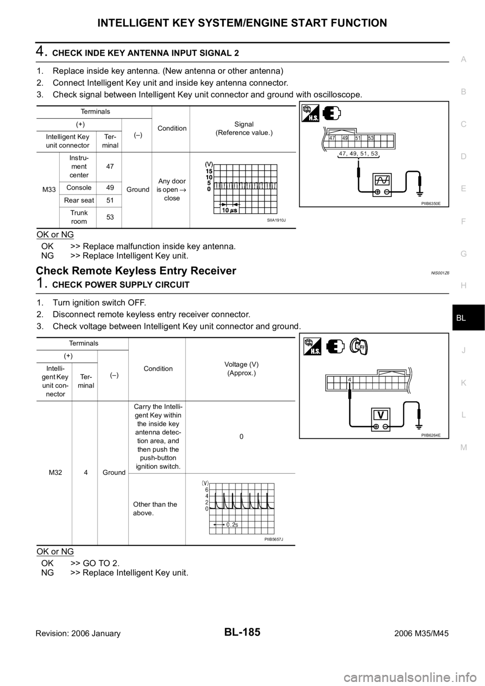
4. CHECK INDE KEY ANTENNA INPUT SIGNAL 2
1. Replace inside key antenna. (New antenna or other antenna)
2. Connect Intelligent Key unit and inside key antenna connector.
3. Check signal between Intelligent Key unit connector and ground with oscilloscope.
OK or NG
OK >> Replace malfunction inside key antenna.
NG >> Replace Intelligent Key unit.
Check Remote Keyless Entry ReceiverNIS001Z6
1. CHECK POWER SUPPLY CIRCUIT
1. Turn ignition switch OFF.
2. Disconnect remote keyless entry receiver connector.
3. Check voltage between Intelligent Key unit connector and ground.
OK or NG
OK >> GO TO 2.
NG >> Replace Intelligent Key unit.
Terminals
ConditionSignal
(Reference value.) (+)
(–)
Intelligent Key
unit connectorTe r -
minal
M33Instru-
ment
center47
GroundAny door
is open
close Console 49
Rear seat 51
Trunk
room53
PIIB6350E
SIIA1910J
Terminals
ConditionVoltage (V)
(Approx.) (+)
(–) Intelli-
gent Key
unit con-
nectorTe r -
minal
M32 4 GroundCarry the Intelli-
gent Key within
the inside key
antenna detec-
tion area, and
then push the
push-button
ignition switch.0
Other than the
above.
PIIB6264E
PIIB5657J
Page 1128 of 5621
INTELLIGENT KEY SYSTEM/ENGINE START FUNCTION
BL-189
C
D
E
F
G
H
J
K
L
MA
B
BL
Revision: 2006 January2006 M35/M45
3. CHECK KEY SLOT SIGNAL
1. Connect key slot connector.
2. Check voltage between key slot connector and ground.
OK or NG
OK >> Check the condition of harness and connector.
NG >> Repair or replace harness between BCM and key slot.
Terminals
ConditionVoltage (V)
(Approx.) (+)
(–)
Key slot
connectorTerminal
M146
GroundCheck the voltage just
after the Intelligent Key
is inserted into the key
slot and the ignition
switch is turned to
START.The pointer of
the analog
tester fluctu-
ates. 7
PIIB6263E
Page 1153 of 5621
BL-214
TRUNK LID OPENER
Revision: 2006 January2006 M35/M45
CONSULT-II Function (BCM)NIS001ZR
CONSULT-II can display each diagnostic item using the diagnostic test modes shown following.
CONSULT-II INSPECTION PROCEDURE
CAUTION:
If CONSULT-II is used with no connection of CONSULT-II CONVERTER, malfunctions might be
detected in self-diagnosis depending on control unit which carry out CAN communication.
1. Turn ignition switch “OFF”.
2. Connect “CONSULT-II” and CONSULT-II CONVERTER to data
link connector (1).
3. Turn ignition switch “ON”.
4. Touch “START(NISSAN BASED VHCL)”.
5. Touch “BCM”.
If “BCM” is not indicated, go to GI-40, "
CONSULT-II Data Link
Connector (DLC) Circuit" .
BCM diagnosis
partInspection item, self-diagnosis
modeContent
TRUNKDATA MONITOR Displays the input data of BCM in real time basis.
ACTIVE TEST Give a drive signals to load to check the operation check.
PBIB2712E
BCIA0029E
BCIA0030E
Page 1155 of 5621
BL-216
TRUNK LID OPENER
Revision: 2006 January2006 M35/M45
Trouble DiagnosisNIS001ZS
TRUNK DOSE NOT OPEN WITH TRUNK LID OPENER SWITCH / WITH INTELLIGENT KEY
1. CHECK TRUNK LID OPENER CANCEL SWITCH
Check trunk lid opener cancel switch position.
Does trunk lid opener cancel switch turn OFF (CANCEL)?
Yes >> Turn on trunk lid opener cancel switch.
No >> GO TO 2.
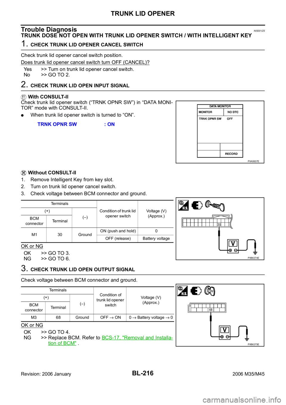
2. CHECK TRUNK LID OPEN INPUT SIGNAL
With CONSULT-II
Check trunk lid opener switch (“TRNK OPNR SW”) in “DATA MONI-
TOR” mode with CONSULT-II.
When trunk lid opener switch is turned to “ON”.
Without CONSULT-II
1. Remove Intelligent Key from key slot.
2. Turn on trunk lid opener cancel switch.
3. Check voltage between BCM connector and ground.
OK or NG
OK >> GO TO 3.
NG >> GO TO 6.
3. CHECK TRUNK LID OPEN OUTPUT SIGNAL
Check voltage between BCM connector and ground.
OK or NG
OK >> GO TO 4.
NG >> Replace BCM. Refer to BCS-17, "
Removal and Installa-
tion of BCM" . TRNK OPNR SW : ON
PIIA9937E
Terminals
Condition of trunk lid
opener switchVoltage (V)
(Approx.) (+)
(–)
BCM
connectorTerminal
M1 30 GroundON (push and hold) 0
OFF (release) Battery voltage
PIIB6374E
Te r m i n a l s
Condition of
trunk lid opener
switchVoltage (V)
(Approx.) (+)
(–)
BCM
connectorTerminal
M3 68 Ground OFF
ON 0 Battery voltage 0
PIIB6375E
Page 1161 of 5621
BL-222
VEHICLE SECURITY (THEFT WARNING) SYSTEM
Revision: 2006 January2006 M35/M45
System DescriptionNIS001ZU
DESCRIPTION
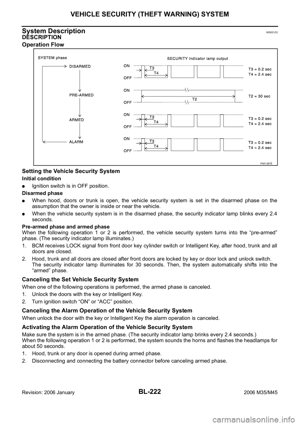
Operation Flow
Setting the Vehicle Security System
Initial condition
Ignition switch is in OFF position.
Disarmed phase
When hood, doors or trunk is open, the vehicle security system is set in the disarmed phase on the
assumption that the owner is inside or near the vehicle.
When the vehicle security system is in the disarmed phase, the security indicator lamp blinks every 2.4
seconds.
Pre-armed phase and armed phase
When the following operation 1 or 2 is performed, the vehicle security system turns into the “pre-armed”
phase. (The security indicator lamp illuminates.)
1. BCM receives LOCK signal from front door key cylinder switch or Intelligent Key, after hood, trunk and all
doors are closed.
2. Hood, trunk and all doors are closed after front doors are locked by key or door lock and unlock switch.
The security indicator lamp illuminates for 30 seconds. Then, the system automatically shifts into the
“armed” phase.
Canceling the Set Vehicle Security System
When one of the following operations is performed, the armed phase is canceled.
1. Unlock the doors with the key or Intelligent Key.
2. Turn ignition switch “ON” or “ACC” position.
Canceling the Alarm Operation of the Vehicle Security System
When unlock the door with the key or Intelligent Key the alarm operation is canceled.
Activating the Alarm Operation of the Vehicle Security System
Make sure the system is in the armed phase. (The security indicator lamp brinks every 2.4 seconds.)
When the following operation 1 or 2 is performed, the system sounds the horns and flashes the headlamps for
about 50 seconds.
1. Hood, trunk or any door is opened during armed phase.
2. Disconnecting and connecting the battery connector before canceling armed phase.
PIIA1367E
Page 1163 of 5621

BL-224
VEHICLE SECURITY (THEFT WARNING) SYSTEM
Revision: 2006 January2006 M35/M45
VEHICLE SECURITY SYSTEM ALARM OPERATION
The vehicle security system is triggered by
opening a door
opening the trunk
opening the hood
detection of battery disconnect and connect.
The vehicle security system will be triggered once the system is in armed phase,
when BCM receives a ground signal at terminals 12 (passenger side door), 13 (rear RH door), 57 (trunk), 62
(driver side door), 63 (rear LH door), or receives a signal from the IPDM E/R (hood switch).
When the vehicle security system is triggered,
ground is supplied intermittently to both headlamp relay and horn relay.
When headlamp relay and horn relay are energized, then power is supplied to headlamps (LH and RH) and
horns (HIGH and LOW).
The headlamps flash and the horn sounds intermittently.
The alarm automatically turns off after 50 seconds, but will reactivate if the vehicle is tampered with again.
VEHICLE SECURITY SYSTEM DEACTIVATION
To deactivate the vehicle security system, a door or the trunk must be unlocked with the key, Intelligent Key.
When the key is used to unlock a door, BCM terminal 22 receives signal
from the power window main switch (door lock and unlock switch) terminal 14.
When the BCM receives either one of these signals or unlock signal from key cylinder switch or Intelligent Key,
the vehicle security system is deactivated. (Disarmed phase)
PANIC ALARM OPERATION
Intelligent Key system may or may not operate vehicle security system (horn and headlamps) as required.
When the Intelligent Key system is triggered, ground is supplied intermittently to both headlamp relay and horn
relay.
When headlamp relay and horn relay are energized, then power is supplied to headlamps (LH and RH) and
horns (HIGH and LOW).
The headlamp flashes and the horn sounds intermittently.
The alarm automatically turns off after 25 seconds or when BCM receives any signal from Intelligent Key.
CAN Communication System DescriptionNIS001ZV
CAN (Controller Area Network) is a serial communication line for real time application. It is an on-vehicle mul-
tiplex communication line with high data communication speed and excellent error detection ability. Many elec-
tronic control units are equipped onto a vehicle, and each control unit shares information and links with other
control units during operation (not independent). In CAN communication, control units are connected with 2
communication lines (CAN H line, CAN L line) allowing a high rate of information transmission with less wiring.
Each control unit transmits/receives data but selectively reads required data only.
CAN Communication UnitNIS001ZW
Refer to LAN-34, "CAN COMMUNICATION" .