2006 INFINITI M35 ignition
[x] Cancel search: ignitionPage 5120 of 5621
PRE-CRASH SEAT BELT
SB-21
C
D
E
F
G
I
J
K
L
MA
B
SB
Revision: 2006 January2006 M35/M45
Seat Belt Buckle Switch (Passenger Side) Circuit CheckNHS0008C
1. CHECK PRE-CRASH SEAT BELT CONTROL UNIT INPUT SIGNAL
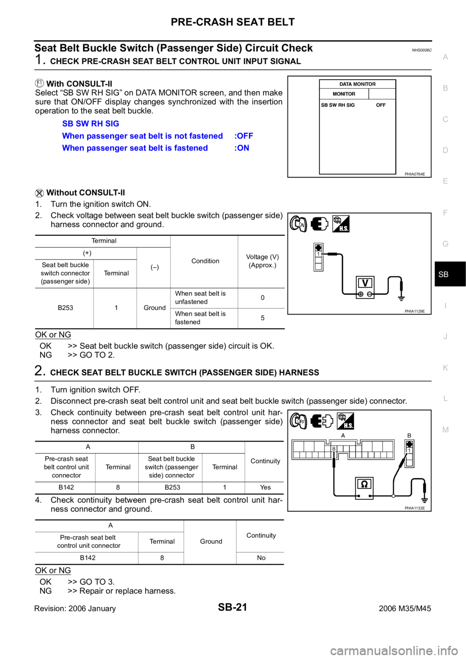
With CONSULT-II
Select “SB SW RH SIG” on DATA MONITOR screen, and then make
sure that ON/OFF display changes synchronized with the insertion
operation to the seat belt buckle.
Without CONSULT-II
1. Turn the ignition switch ON.
2. Check voltage between seat belt buckle switch (passenger side)
harness connector and ground.
OK or NG
OK >> Seat belt buckle switch (passenger side) circuit is OK.
NG >> GO TO 2.
2. CHECK SEAT BELT BUCKLE SWITCH (PASSENGER SIDE) HARNESS
1. Turn ignition switch OFF.
2. Disconnect pre-crash seat belt control unit and seat belt buckle switch (passenger side) connector.
3. Check continuity between pre-crash seat belt control unit har-
ness connector and seat belt buckle switch (passenger side)
harness connector.
4. Check continuity between pre-crash seat belt control unit har-
ness connector and ground.
OK or NG
OK >> GO TO 3.
NG >> Repair or replace harness.SB SW RH SIG
When passenger seat belt is not fastened :OFF
When passenger seat belt is fastened :ON
PHIA0764E
Terminal
ConditionVoltage (V)
(Approx.) (+)
(–) Seat belt buckle
switch connector
(passenger side) Te r m i n a l
B253 1 GroundWhen seat belt is
unfastened0
When seat belt is
fastened5
PHIA1129E
AB
Continuity Pre-crash seat
belt control unit
connectorTerminalSeat belt buckle
switch (passenger
side) connectorTerminal
B142 8 B253 1 Yes
A
GroundContinuity
Pre-crash seat belt
control unit connectorTerminal
B142 8 No
PHIA1133E
Page 5122 of 5621
PRE-CRASH SEAT BELT
SB-23
C
D
E
F
G
I
J
K
L
MA
B
SB
Revision: 2006 January2006 M35/M45
2. CHECK PRE-CRASH SEAT BELT CONTOROL UNIT INPUT SIGNAL
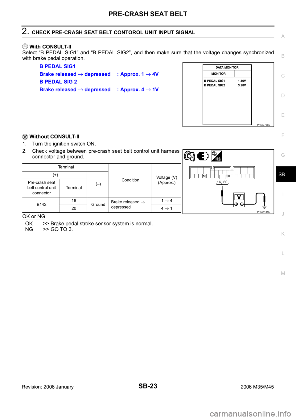
With CONSULT-II
Select “B PEDAL SIG1” and “B PEDAL SIG2”, and then make sure that the voltage changes synchronized
with brake pedal operation.
Without CONSULT-II
1. Turn the ignition switch ON.
2. Check voltage between pre-crash seat belt control unit harness
connector and ground.
OK or NG
OK >> Brake pedal stroke sensor system is normal.
NG >> GO TO 3.B PEDAL SIG1
Brake released
depressed : Approx. 1 4V
B PEDAL SIG 2
Brake released
depressed : Approx. 4 1V
PHIA0766E
Terminal
ConditionVoltage (V)
(Approx.) (+)
(–) Pre-crash seat
belt control unit
connectorTe r m i n a l
B14216
GroundBrake released
depressed1 4
20 4
1PHIA1134E
Page 5123 of 5621
SB-24
PRE-CRASH SEAT BELT
Revision: 2006 January2006 M35/M45
3. CHECK BRAKE PEDAL STROKE SENSOR HARNESS
1. Turn the ignition switch OFF.
2. Disconnect pre-crash seat belt control unit connector and brake pedal stroke sensor connector.
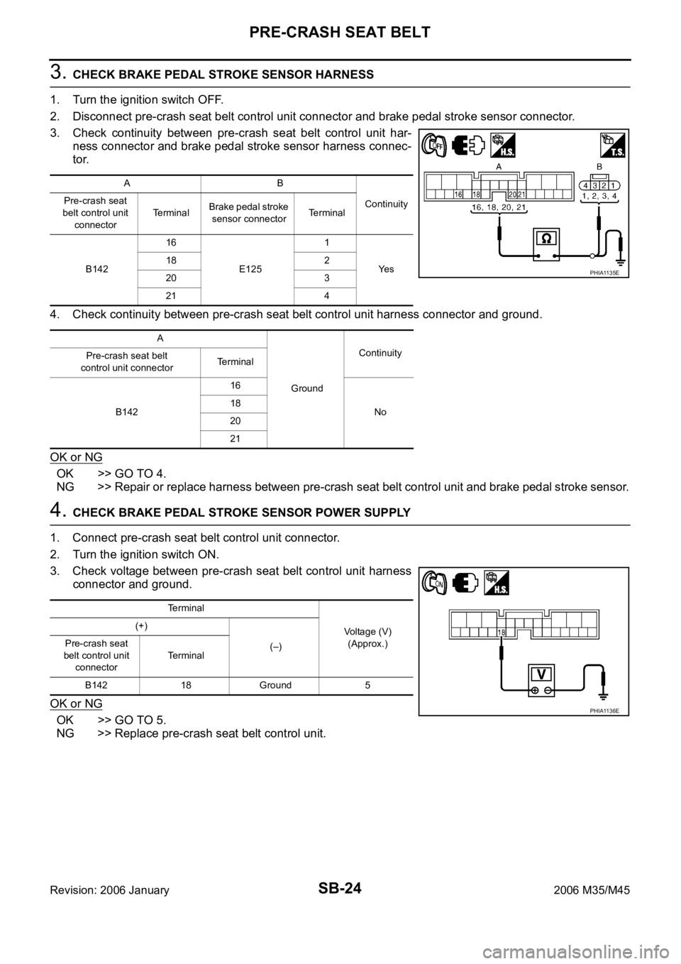
3. Check continuity between pre-crash seat belt control unit har-
ness connector and brake pedal stroke sensor harness connec-
tor.
4. Check continuity between pre-crash seat belt control unit harness connector and ground.
OK or NG
OK >> GO TO 4.
NG >> Repair or replace harness between pre-crash seat belt control unit and brake pedal stroke sensor.
4. CHECK BRAKE PEDAL STROKE SENSOR POWER SUPPLY
1. Connect pre-crash seat belt control unit connector.
2. Turn the ignition switch ON.
3. Check voltage between pre-crash seat belt control unit harness
connector and ground.
OK or NG
OK >> GO TO 5.
NG >> Replace pre-crash seat belt control unit.
AB
Continuity Pre-crash seat
belt control unit
connectorTe r m i n a lBrake pedal stroke
sensor connectorTerminal
B14216
E1251
Ye s 18 2
20 3
21 4
A
GroundContinuity
Pre-crash seat belt
control unit connectorTerminal
B14216
No 18
20
21
PHIA1135E
Terminal
Voltage (V)
(Approx.) (+)
(–) Pre-crash seat
belt control unit
connectorTerminal
B142 18 Ground 5
PHIA1136E
Page 5125 of 5621
SB-26
PRE-CRASH SEAT BELT
Revision: 2006 January2006 M35/M45
2. CHECK LH SEAT BELT MOTOR HARNESS
1. Turn the ignition switch OFF.
2. Disconnect pre-crash seat belt control unit connector and pre-crash seat belt motor LH connector.
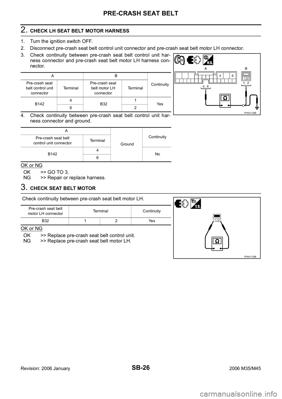
3. Check continuity between pre-crash seat belt control unit har-
ness connector and pre-crash seat belt motor LH harness con-
nector.
4. Check continuity between pre-crash seat belt control unit har-
ness connector and ground.
OK or NG
OK >> GO TO 3.
NG >> Repair or replace harness.
3. CHECK SEAT BELT MOTOR
Check continuity between pre-crash seat belt motor LH.
OK or NG
OK >> Replace pre-crash seat belt control unit.
NG >> Replace pre-crash seat belt motor LH.
AB
Continuity Pre-crash seat
belt control unit
connectorTe r m i n a lPre-crash seat
belt motor LH
connectorTerminal
B1424
B321
Ye s
62
A
GroundContinuity
Pre-crash seat belt
control unit connectorTerminal
B1424
No
6
PHIA1138E
Pre-crash seat belt
motor LH connectorTerminal Continuity
B32 1 2 Yes
PHIA1139E
Page 5126 of 5621
![INFINITI M35 2006 Factory Service Manual PRE-CRASH SEAT BELT
SB-27
C
D
E
F
G
I
J
K
L
MA
B
SB
Revision: 2006 January2006 M35/M45
Pre-Crash Seat Belt Motor RH Circuit Check [B2451]NHS0008F
1. CHECK RH SEAT BELT MOTOR CIRCUIT
With CONSULT-II
S INFINITI M35 2006 Factory Service Manual PRE-CRASH SEAT BELT
SB-27
C
D
E
F
G
I
J
K
L
MA
B
SB
Revision: 2006 January2006 M35/M45
Pre-Crash Seat Belt Motor RH Circuit Check [B2451]NHS0008F
1. CHECK RH SEAT BELT MOTOR CIRCUIT
With CONSULT-II
S](/manual-img/42/57023/w960_57023-5125.png)
PRE-CRASH SEAT BELT
SB-27
C
D
E
F
G
I
J
K
L
MA
B
SB
Revision: 2006 January2006 M35/M45
Pre-Crash Seat Belt Motor RH Circuit Check [B2451]NHS0008F
1. CHECK RH SEAT BELT MOTOR CIRCUIT
With CONSULT-II
Select SELF-DIAG RESULTS” of CONSULT-II, and then make sure
that “SB MOTOR RH CIRC” is displayed.
Without CONSULT-II
When CONSULT-II is not used, omit this inspection, and then GO TO 2.
Displayed B2451?
Ye s > > G O T O 2 .
No >> Pre-crash seat belt motor RH circuit is OK.
2. CHECK RH SEAT BELT MOTOR HARNESS
1. Turn the ignition switch OFF.
2. Disconnect pre-crash seat belt control unit connector and pre-crash seat belt motor RH connector.
3. Check continuity between pre-crash seat belt control unit har-
ness connector and pre-crash seat belt motor RH harness con-
nector.
4. Check continuity between pre-crash seat belt control unit har-
ness connector and ground.
OK or NG
OK >> GO TO 3.
NG >> Repair or replace harness.
CONSULT-II display CONSULT-II display code
NO DTC –
SB MOTOR RH CIRC B2451
PHIA0767E
AB
Continuity Pre-crash seat
belt control unit
connectorTerminalPre-crash seat
belt motor RH
connectorTerminal
B1421
B82
Ye s
3 1
A
GroundContinuity
Pre-crash seat belt
control unit connectorTerminal
B1421
No
3
PHIA1140E
Page 5129 of 5621
SB-30
SEAT BELTS
Revision: 2006 January2006 M35/M45
SEAT BELTSPFP:86884
System DescriptionNHS0008I
SEAT BELT WARNING CHIME
With ignition switch turned ON and seat belt unfastened (seat belt switch ON), warning chime will sound
for approximately 6 seconds.
If warning chime does not sound, refer to DI-74, "Seat Belt Buckle Switch Signal Inspection" .
SEAT BELT WARNING LAMP
Fasten driver's seat belt.
The seat belt warning lamp should go out.
If the seat belt warning lamp does not go out, refer to DI-43, "Wiring Diagram — WARN —" .
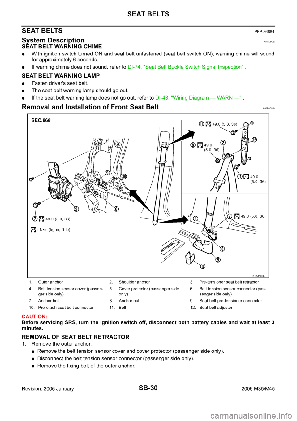
Removal and Installation of Front Seat Belt NHS0008J
CAUTION:
Before servicing SRS, turn the ignition switch off, disconnect both battery cables and wait at least 3
minutes.
REMOVAL OF SEAT BELT RETRACTOR
1. Remove the outer anchor.
Remove the belt tension sensor cover and cover protector (passenger side only).
Disconnect the belt tension sensor connector (passenger side only).
Remove the fixing bolt of the outer anchor.
1. Outer anchor 2. Shoulder anchor 3. Pre-tensioner seat belt retractor
4. Belt tension sensor cover (passen-
ger side only)5. Cover protector (passenger side
only)6. Belt tension sensor connector (pas-
senger side only)
7. Anchor bolt 8. Anchor nut 9. Seat belt pre-tensioner connector
10. Pre-crash seat belt connector 11. Bolt 12. Seat belt adjuster
PHIA1106E
Page 5132 of 5621
SEAT BELTS
SB-33
C
D
E
F
G
I
J
K
L
MA
B
SB
Revision: 2006 January2006 M35/M45
INSTALLATION OF SEAT BELT BUCKLE
Install in the reverse order of removal.
Tighten by specified torque.
Seat Belt InspectionNHS0008L
AFTER A COLLISION
WAR NING :
Inspect all seat belt assemblies including retractors and attaching hardware after any collision.
NISSAN / INFINITI recommends that all seat belt assemblies in use during a collision be replaced
unless the collision was minor and the belts show no damage and continue to operate properly. Fail-
ure to do so could result in serious personal injury in an accident. Seat belt assemblies not in use dur-
ing a collision should also be replaced if either damage or improper operation is noted. Seat belt pre-
tensioned should be replaced even if the seat belts are not in use during a frontal collision in which
the air bags are deployed.
Replace any seat belt assembly (including anchor bolts) if:
The seat belt was in use at the time of a collision (except for minor collisions and the belts, retractors and
buckles show no damage and continue to operate properly).
The seat belt was damaged in an accident. (i.e. torn webbing, bent retractor or guide, etc.)
The seat belt attaching point was damaged in an accident. Inspect the seat belt attaching area for damage
or distortion and repair as necessary before installing a new seat belt assembly.
Anchor bolts are deformed or worn out.
The seat belt pre-tensioner should be replaced even if the seat belts are not in use during the collision in
which the air bags are deployed.
PRELIMINARY CHECKS
1. Check the seat belt warning lamp/chime for proper operation as follows:
a. Switch ignition ON. The seat belt warning lamp should illuminate. Also, the seat belt warning chime should
sound for about six seconds.
b. Fasten driver's seat belt. The seat belt warning lamp should go out and the chime (if sounding) should
stop.
2. If the air bag warning lamp is blinking, conduct self-diagnosis using CONSULT-II, and air bag warning
lamp. Refer to SRS-19, "
SRS Operation Check" .
3. Check that the seat belt retractor, seat belt anchor and buckle bolts are securely attached.
4. Check the shoulder seat belt guide and shoulder belt height adjuster for front seats. Ensure guide swivels
freely and that webbing lays flat and does not bind in guide. Ensure height adjuster operates properly and
holds securely.
5. Check retractor operation:
a. Fully extend the seat belt webbing and check for twists, tears or other damage.
b. Allow the seat belt to retract. Ensure that webbing returns smoothly and completely into the retractor. If
the seat belt does not return smoothly, wipe the inside of the loops with a clean paper cloth. Because dirt
built up in the loops of the upper anchors can cause the seat belts to retract slowly.
c. Fasten the seat belt. Check the seat belt returns smoothly and completely to the retractor. If the webbing
does not return smoothly, the cause may be an accumulation of dust or dirt. Use the “SEAT BELT TAPE
SET” and perform the following steps.
Inspect the front seat belt though-anchor
1. Pull the seat belt out to a length of 500 mm (19.69 in) or more.
2. Use a clip or other device to the fix the seat belt at the center pillar webbing opening.
3. Pass a thin wire though the though-anchor webbing opening. Hold both ends of the wire and pull it
tantly while moving it up and down several times along the webbing opening surface to move matter
stuck there.
4. Any dirt that can not be removed with the wire can be removed by cleaning the opening with a clean
cloth.
5. Apply tape at the point where the webbing contacts the though-anchor webbing opening. Tightening torque : 49.0 Nꞏm (5.0 kg-m, 36 ft-lb)
Page 5144 of 5621
BATTERY
SC-7
C
D
E
F
G
H
I
J
L
MA
B
SC
Revision: 2006 January2006 M35/M45
If, after charging, the specific gravity of any two cells varies more than 0.050, the battery should be
replaced.
Trouble Diagnosis with Battery/Starting/Charging System Tester (Battery)NKS003NG
CAUTION:
When working with batteries, always wear appropriate eye protection.
NOTE:
To ensure a complete and thorough diagnosis, the battery, starter and alternator test segments must be
done as a set from start to finish.
If battery surface charge is detected while testing, the tester will prompt you to turn on the headlamps to
remove the surface charge.
If necessary, the tester will prompt you to determine if the battery temperature is above or below 0 C (32
F). Choose the appropriate selection by pressing the up or down arrow button, then press “ENTER” to
make the selection.
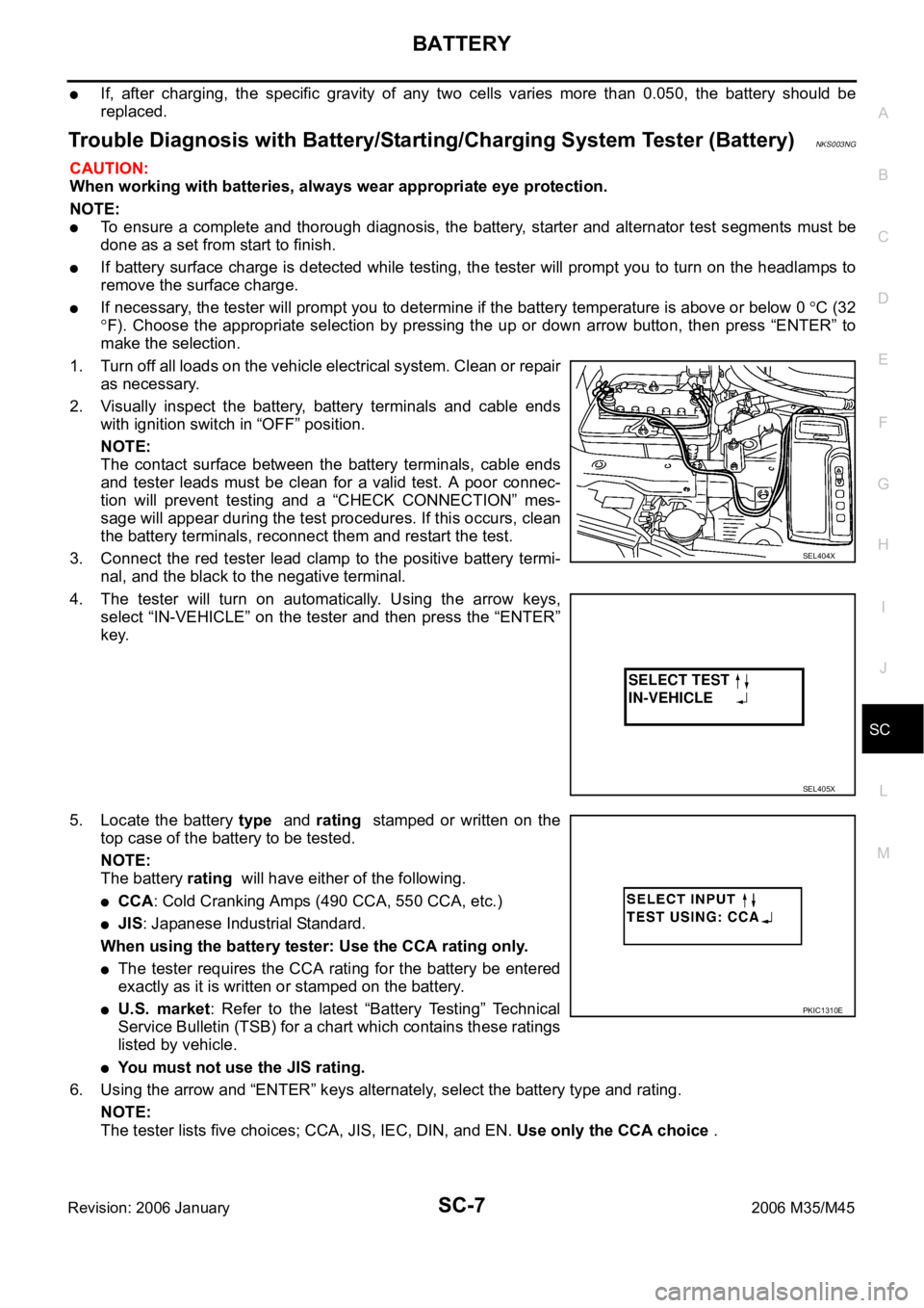
1. Turn off all loads on the vehicle electrical system. Clean or repair
as necessary.
2. Visually inspect the battery, battery terminals and cable ends
with ignition switch in “OFF” position.
NOTE:
The contact surface between the battery terminals, cable ends
and tester leads must be clean for a valid test. A poor connec-
tion will prevent testing and a “CHECK CONNECTION” mes-
sage will appear during the test procedures. If this occurs, clean
the battery terminals, reconnect them and restart the test.
3. Connect the red tester lead clamp to the positive battery termi-
nal, and the black to the negative terminal.
4. The tester will turn on automatically. Using the arrow keys,
select “IN-VEHICLE” on the tester and then press the “ENTER”
key.
5. Locate the battery type and rating stamped or written on the
top case of the battery to be tested.
NOTE:
The battery rating will have either of the following.
CCA: Cold Cranking Amps (490 CCA, 550 CCA, etc.)
JIS: Japanese Industrial Standard.
When using the battery tester: Use the CCA rating only.
The tester requires the CCA rating for the battery be entered
exactly as it is written or stamped on the battery.
U.S. market: Refer to the latest “Battery Testing” Technical
Service Bulletin (TSB) for a chart which contains these ratings
listed by vehicle.
You must not use the JIS rating.
6. Using the arrow and “ENTER” keys alternately, select the battery type and rating.
NOTE:
The tester lists five choices; CCA, JIS, IEC, DIN, and EN. Use only the CCA choice .
SEL404X
SEL405X
PKIC1310E