2006 INFINITI M35 ignition
[x] Cancel search: ignitionPage 4849 of 5621

PG-22
IPDM E/R (INTELLIGENT POWER DISTRIBUTION MODULE ENGINE ROOM)
Revision: 2006 January2006 M35/M45
DATA MONITOR
Operation Procedure
1. Touch “DATA MONITOR” on “SELECT MONITOR ITEM ” screen.
2. Touch “ALL SIGNALS”, “MAIN SIGNALS” or “SELECTION FROM MENU” on the “DATA MONITOR”
screen.
3. Touch the required monitoring item on “SELECTION FROM MENU”. In “ALL SIGNALS”, all items are
monitored. In “MAIN SIGNALS”, predetermined items are monitored.
4. Touch “START”.
5. Touch “RECORD” while monitoring to record the status of the item being monitored. To stop recording,
touch “STOP”.
All Signals, Main Signals, Selection From Menu
NOTE:
Perform monitoring of IPDM E/R data with the ignition switch ON. When the ignition switch is at ACC, the display may not be cor-
rect.
*1: Only the vehicle with day time light system operates. ALL SIGNALS All items will be monitored.
MAIN SIGNALS Monitor the predetermined item.
SELECTION FROM MENU Select any item for monitoring.
Item nameCONSULT-II
screen displayDisplay or unitMonitor item selection
Description
ALL
SIGNALSMAIN
SIGNALSSELECTION
FROM
MENU
Motor fan request MOTOR FAN REQ 1/2/3/4
Signal status input from ECM
A/C Compressor
requestAC COMP REQ ON/OFF
Signal status input from ECM
Tail & clearance
requestTAIL&CLR REQ ON/OFF
Signal status input from BCM
Headlamp LO
requestHL LO REQ ON/OFF
Signal status input from BCM
Headlamp HI
requestHL HI REQ ON/OFF
Signal status input from BCM
Front fog lamp
request FR FOG REQ ON/OFF
Signal status input from BCM
Front wiper request FR WIP REQSTOP/1LOW/
LOW/HI
Signal status input from BCM
Wiper auto stop WIP AUTO STOP ACT P/STOP P
Output status of IPDM E/R
Wiper protection WIP PROT OFF/BLOCK
Control status of IPDM E/R
Starter request ST RLY REQ ON/OFF
Signal status input from BCM
Ignition relay status IGN RLY ON/OFF
Ignition relay status monitored
with IPDM E/R
Rear window defog-
ger requestRR DEF REQ ON/OFF
Signal status input from BCM
Oil pressure switch OIL P SW OPEN/CLOSE
Signal status input in IPDM E/R
Daytime running
light requestDTRL REQ
*1ON/OFFSignal status input from BCM
Hood switch HOOD SW ON/OFF
Signal status input in IPDM E/R
Theft warning horn
requestTHFT HRN REQ ON/OFF
Signal status input from BCM
Horn chirp HORN CHIRP ON/OFF
Output status of IPDM E/R
Page 4851 of 5621

PG-24
IPDM E/R (INTELLIGENT POWER DISTRIBUTION MODULE ENGINE ROOM)
Revision: 2006 January2006 M35/M45
Auto Active TestNKS004E7
DESCRIPTION
In auto active test mode, operation inspection can be performed when IPDM E/R sends a drive signal to the
following systems:
Rear window defogger
Front wiper (LO, HI)
Tail lamps, parking lamps and license plate lamps
Front fog lamps
Headlamps (LO, HI)
A/C compressor (magnetic clutch)
Cooling fan
Oil pressure warning lamp
OPERATION PROCEDURE
1. Close hood and front door (passenger side), and then lift wiper arms away from windshield (to prevent
glass damage by wiper operation).
NOTE:
When auto active test is performed with hood opened, sprinkle water on windshield beforehand.
2. Turn ignition switch OFF.
3. Turn ignition switch ON, and within 20 seconds, press driver's door switch 10 times (close other doors).
Then turn ignition switch OFF.
4. Turn ignition switch ON within 10 seconds after ignition switch OFF.
5. When auto active test mode is actuated, horn chirps once. Oil pressure warning lamp starts blinking.
6. After a series of operations is repeated three times, auto active test is completed.
NOTE:
When auto active test mode has to be cancelled halfway, turn ignition switch OFF.
CAUTION:
Never start the engine.
If the engine starting operation is made, delete DTC on the self-diag results of CONSULT-II.
Refer to BL-81, "
CONSULT-II Application Items" .
Be sure to inspect GW-52, "Door Switch Check" when the auto active test cannot be performed.
Page 4857 of 5621

PG-30
IPDM E/R (INTELLIGENT POWER DISTRIBUTION MODULE ENGINE ROOM)
Revision: 2006 January2006 M35/M45
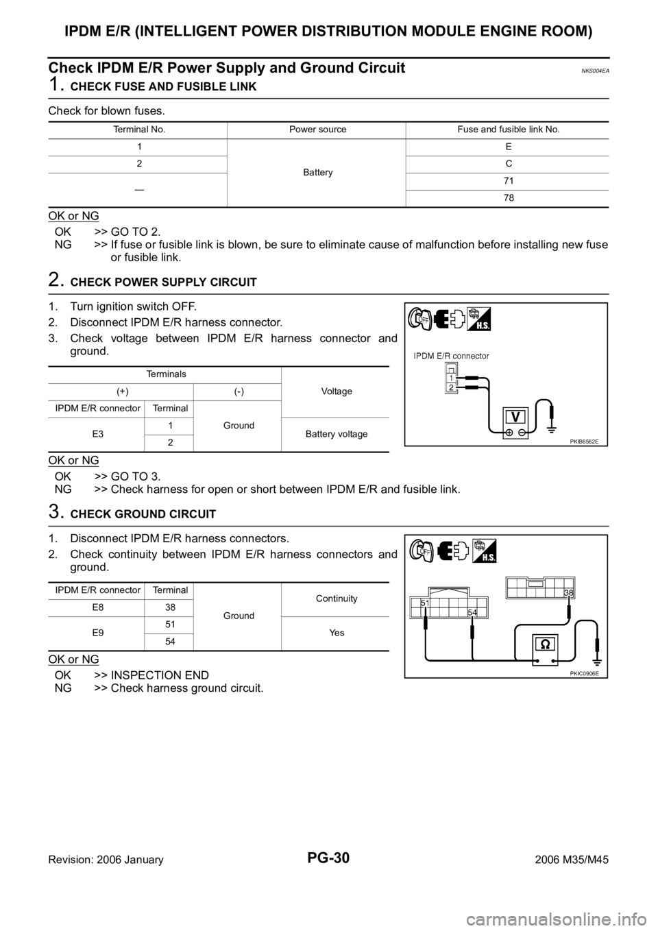
Check IPDM E/R Power Supply and Ground CircuitNKS004EA
1. CHECK FUSE AND FUSIBLE LINK
Check for blown fuses.
OK or NG
OK >> GO TO 2.
NG >> If fuse or fusible link is blown, be sure to eliminate cause of malfunction before installing new fuse
or fusible link.
2. CHECK POWER SUPPLY CIRCUIT
1. Turn ignition switch OFF.
2. Disconnect IPDM E/R harness connector.
3. Check voltage between IPDM E/R harness connector and
ground.
OK or NG
OK >> GO TO 3.
NG >> Check harness for open or short between IPDM E/R and fusible link.
3. CHECK GROUND CIRCUIT
1. Disconnect IPDM E/R harness connectors.
2. Check continuity between IPDM E/R harness connectors and
ground.
OK or NG
OK >> INSPECTION END
NG >> Check harness ground circuit.
Terminal No. Power source Fuse and fusible link No.
1
BatteryE
2C
—71
78
Terminals
Vo l ta g e (+) (-)
IPDM E/R connector Terminal
Ground
E31
Battery voltage
2
PKIB6562E
IPDM E/R connector Terminal
GroundContinuity
E8 38
E951
Ye s
54
PKIC0906E
Page 4860 of 5621

PDU (POWER DISTRIBUTION UNIT)
PG-33
C
D
E
F
G
H
I
J
L
MA
B
PG
Revision: 2006 January2006 M35/M45
PDU (POWER DISTRIBUTION UNIT)PFP:285F1
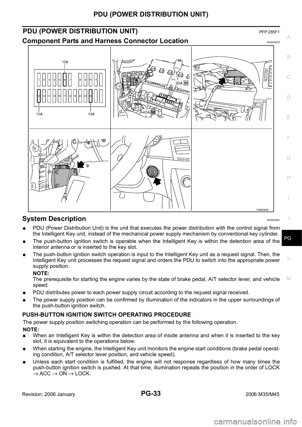
Component Parts and Harness Connector LocationNKS004ED
System DescriptionNKS004EE
PDU (Power Distribution Unit) is the unit that executes the power distribution with the control signal from
the Intelligent Key unit, instead of the mechanical power supply mechanism by conventional key cylinder.
The push-button ignition switch is operable when the Intelligent Key is within the detention area of the
interior antenna or is inserted to the key slot.
The push-button ignition switch operation is input to the Intelligent Key unit as a request signal. Then, the
Intelligent Key unit processes the request signal and orders the PDU to switch into the appropriate power
supply position.
NOTE:
The prerequisite for starting the engine varies by the state of brake pedal, A/T selector lever, and vehicle
speed.
PDU distributes power to each power supply circuit according to the request signal received.
The power supply position can be confirmed by illumination of the indicators in the upper surroundings of
the push-button ignition switch.
PUSH-BUTTON IGNITION SWITCH OPERATING PROCEDURE
The power supply position switching operation can be performed by the following operation.
NOTE:
When an Intelligent Key is within the detection area of inside antenna and when it is inserted to the key
slot, it is equivalent to the operations below.
When starting the engine, the Intelligent Key unit monitors the engine start conditions (brake pedal operat-
ing condition, A/T selector lever position, and vehicle speed).
Unless each start condition is fulfilled, the engine will not response regardless of how many times the
push-button ignition switch is pushed. At that time, illumination repeats the position in the order of LOCK
ACC ON LOCK.
PIIB6094E
Page 4861 of 5621

PG-34
PDU (POWER DISTRIBUTION UNIT)
Revision: 2006 January2006 M35/M45
*1: When the A/T selector lever position is N position, the engine start condition is different according to the vehicle speed.
At vehicle speed of 5 km/h or less, the engine can start only when the brake pedal is depressed.
At vehicle speed of 5 km/h or more, the engine can start even if the brake pedal is not depressed. (It is the same as “Engine stall
return operation while driving”.)
*2: When the A/T selector lever position is any position other than P position and when the vehicle speed is 5 km/h or more, the engine
stop condition is different.
Press and hold the push-button ignition switch for 2 seconds or more. (When the push-button ignition switch is pressed for too short
a time, the operation may be invalid, so properly press and hold to prevent the incorrect operation.)
Press the push-button ignition switch 3 times within 1.5 seconds. (Emergency stop operation) Power supply positionEngine start/stop condition Push-button ignition
switch operation fre-
quency Brake pedal operation condition A/T selector lever position
LOCK
ACCNot depressed
(When A/T selector lever is in any posi-
tion other than P or N, there will be no
effect even if it is depressed.)Any position other than P or N
(When the brake pedal is not
depressed, there will be no effect even
if the A/T selector lever is in P or N
position.)1
LOCK
ACC ONNot depressed
(When A/T selector lever is in any posi-
tion other than P or N, there will be no
effect even if it is depressed.)Any position other than P or N
(When the brake pedal is not
depressed, there will be no effect even
if the A/T selector lever is in P or N
position.)2
LOCK
ACC ON
LOCKNot depressed
(When A/T selector lever is in any posi-
tion other than P or N, there will be no
effect even if it is depressed.)Any position other than P or N
(When the brake pedal is not
depressed, there will be no effect even
if the A/T selector lever is in P or N
position.)3
LOCK
START
ACC
START
ON
START
(Engine start)Depressed P or N position (*1)1
[If the switch is
pushed once, the
engine starts from
any power supply
position (LOCK,
ACC, and ON)]
Engine start condition
LOCK
(Engine stop)— P position 1
Engine start condition
ACC
(Engine stop)— Any position other than P (*2) 1
Engine stall return
operation while driving— N position 1
Page 4864 of 5621

PDU (POWER DISTRIBUTION UNIT)
PG-37
C
D
E
F
G
H
I
J
L
MA
B
PG
Revision: 2006 January2006 M35/M45
Terminals and Reference Value for Intelligent Key UnitNKS004EG
Te r m i -
nalWire
ColorItemCondition
Voltage (V)
Approx. Ignition
Switch
PositionOperation or Conditions
1 SB Power source (Fuse) LOCK — Battery voltage
3 Y IPDM E/R status signal —Engine starting (During Cranking) 5
Other than above 2
8WPush-button ignition
switch
(LOCK LED)LOCK Push-button ignition switch is in LOCK position 0
—Push-button ignition switch is in any position
(Except LOCK position)1.2
9LPush-button ignition
switch
(ACC LED)ACC Push-button ignition switch is in ACC position 0
—Push-button ignition switch is in any position
(Except ACC position)1.2
10 VPush-button ignition
switch
(ON LED)ON Push-button ignition switch is in ON position 0
—Push-button ignition switch is in any position
(Except ON position)1.2
20 B Ground — — 0
30 L/W Ignition switch (ACC) ACC — Battery voltage
31 GR Ignition switch (ON) ON — Battery voltage
34 R PDU feedback signal LOCKPush-button ignition switch is in LOCK state, 30 sec-
onds after all doors closed1
Other than above 0
36 W Ignition signal 2LOCK — Battery voltage
ACC — Battery voltage
ON — 0
37 P CAN-L — — —
38 L CAN-H — — —
39 BR/W Push switch —Depress push-button ignition switch 0
Unpress push-button ignition switch Battery voltage
40 B Ground — — 0
41 Y Power source (Fuse) LOCK — Battery voltage
42 P PDU wake up signal LOCKPush-button ignition switch is in LOCk state, 30 sec-
onds after all doors closedBattery voltage
Other than above 0
44 BR Ignition signal 1LOCK — Battery voltage
ACC — Battery voltage
ON — 0
45 SB ACC signalLOCK — Battery voltage
ACC — 0
ON — 0
56 B Ground — — 0
57 L Power source (Fuse) LOCK — Battery voltage
72 B Ground — — 0
Page 4865 of 5621

PG-38
PDU (POWER DISTRIBUTION UNIT)
Revision: 2006 January2006 M35/M45
Terminals and Reference Value for PDUNKS004EH
Work FlowNKS004EI
1. Check the symptom and customer's requests.
2. Understand outline of system. Refer to PG-33, "
System Description" .
3. Confirm that Intelligent Key system operates normally.
Refer to BL-24, "
POWER DOOR LOCK SYSTEM" .
4. Repair or replace any malfunctioning parts.
Refer to PG-39, "
Trouble Diagnosis Symptom Chart" .
5. INSPECTION END
Te r m i -
nalWire
ColorItemCondition
Voltage (V)
Approx. Ignition
Switch
PositionOperation or Conditions
1 P PDU wake up signal LOCKPush-button ignition switch is in LOCK state, 30 sec-
onds after all doors closeBattery voltage
Other than above 0
4 BR Ignition signal 1LOCK — Battery voltage
ACC — Battery voltage
ON — 0
5 W Ignition signal 2LOCK — Battery voltage
ACC — Battery voltage
ON — 0
8 SB ACC signalLOCK — Battery voltage
ACC — 0
ON — 0
10 B Ground — — 0
11 Y IPDM E/R status signal —Engine starting (During Cranking) 5
Other than above 2
12 R PDU feedback signal LOCKPush-button ignition switch is in LOCK state, 30 sec-
onds after all doors close1
Other than above 0
14 SB Power source (Fuse) LOCK — Battery voltage
15 L Power source (F/L) LOCK — Battery voltage
16 W ACC power outputLOCK — 0
ACC — Battery voltage
ON — Battery voltage
17 G Power source (Fuse) LOCK — Battery voltage
18 BR ON power outputLOCK — 0
ACC — 0
ON — Battery voltage
Page 4866 of 5621

PDU (POWER DISTRIBUTION UNIT)
PG-39
C
D
E
F
G
H
I
J
L
MA
B
PG
Revision: 2006 January2006 M35/M45
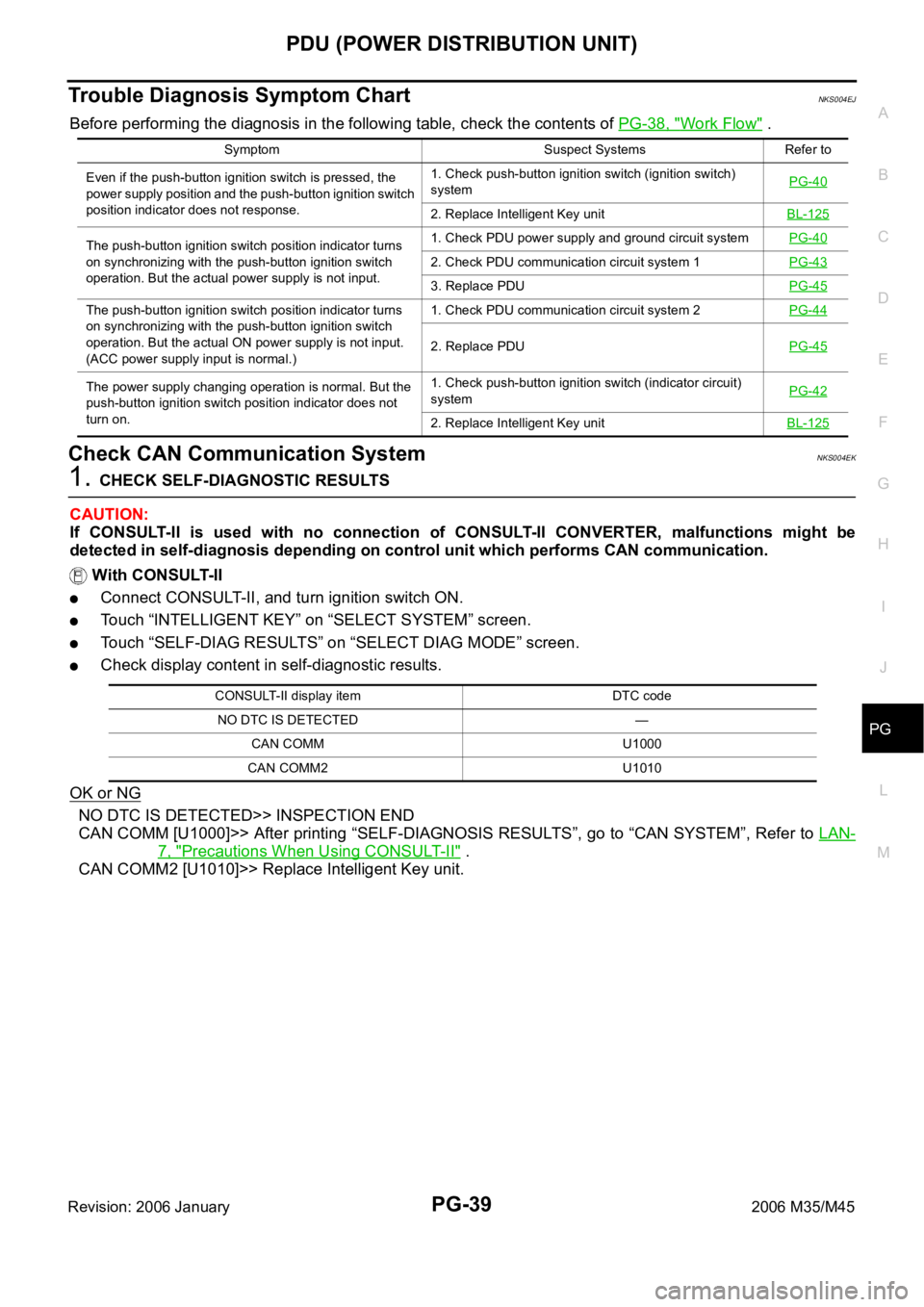
Trouble Diagnosis Symptom ChartNKS004EJ
Before performing the diagnosis in the following table, check the contents of PG-38, "Work Flow" .
Check CAN Communication SystemNKS004EK
1. CHECK SELF-DIAGNOSTIC RESULTS
CAUTION:
If CONSULT-II is used with no connection of CONSULT-II CONVERTER, malfunctions might be
detected in self-diagnosis depending on control unit which performs CAN communication.
With CONSULT-II
Connect CONSULT-II, and turn ignition switch ON.
Touch “INTELLIGENT KEY” on “SELECT SYSTEM” screen.
Touch “SELF-DIAG RESULTS” on “SELECT DIAG MODE” screen.
Check display content in self-diagnostic results.
OK or NG
NO DTC IS DETECTED>> INSPECTION END
CAN COMM [U1000]>> After printing “SELF-DIAGNOSIS RESULTS”, go to “CAN SYSTEM”, Refer to LAN-
7, "Precautions When Using CONSULT-II" .
CAN COMM2 [U1010]>> Replace Intelligent Key unit.
Symptom Suspect Systems Refer to
Even if the push-button ignition switch is pressed, the
power supply position and the push-button ignition switch
position indicator does not response.1. Check push-button ignition switch (ignition switch)
systemPG-40
2. Replace Intelligent Key unitBL-125
The push-button ignition switch position indicator turns
on synchronizing with the push-button ignition switch
operation. But the actual power supply is not input.1. Check PDU power supply and ground circuit systemPG-40
2. Check PDU communication circuit system 1PG-43
3. Replace PDUPG-45
The push-button ignition switch position indicator turns
on synchronizing with the push-button ignition switch
operation. But the actual ON power supply is not input.
(ACC power supply input is normal.)1. Check PDU communication circuit system 2PG-44
2. Replace PDUPG-45
The power supply changing operation is normal. But the
push-button ignition switch position indicator does not
turn on.1. Check push-button ignition switch (indicator circuit)
systemPG-42
2. Replace Intelligent Key unitBL-125
CONSULT-II display item DTC code
NO DTC IS DETECTED —
CAN COMM U1000
CAN COMM2 U1010