2006 INFINITI M35 ignition
[x] Cancel search: ignitionPage 3503 of 5621

GI-40
CONSULT-II CHECKING SYSTEM
Revision: 2006 January2006 M35/M45
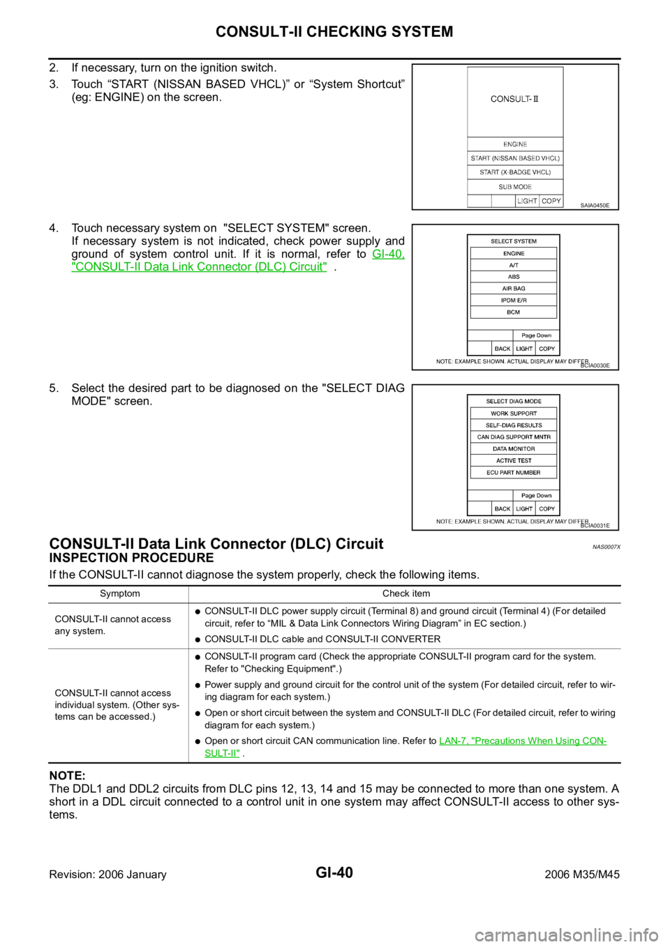
2. If necessary, turn on the ignition switch.
3. Touch “START (NISSAN BASED VHCL)” or “System Shortcut”
(eg: ENGINE) on the screen.
4. Touch necessary system on "SELECT SYSTEM" screen.
If necessary system is not indicated, check power supply and
ground of system control unit. If it is normal, refer to GI-40,
"CONSULT-II Data Link Connector (DLC) Circuit" .
5. Select the desired part to be diagnosed on the "SELECT DIAG
MODE" screen.
CONSULT-II Data Link Connector (DLC) CircuitNAS0007X
INSPECTION PROCEDURE
If the CONSULT-II cannot diagnose the system properly, check the following items.
NOTE:
The DDL1 and DDL2 circuits from DLC pins 12, 13, 14 and 15 may be connected to more than one system. A
short in a DDL circuit connected to a control unit in one system may affect CONSULT-II access to other sys-
tems.
SAIA0450E
BCIA0030E
BCIA0031E
Symptom Check item
CONSULT-II cannot access
any system.
CONSULT-II DLC power supply circuit (Terminal 8) and ground circuit (Terminal 4) (For detailed
circuit, refer to “MIL & Data Link Connectors Wiring Diagram” in EC section.)
CONSULT-II DLC cable and CONSULT-II CONVERTER
CONSULT-II cannot access
individual system. (Other sys-
tems can be accessed.)
CONSULT-II program card (Check the appropriate CONSULT-II program card for the system.
Refer to "Checking Equipment".)
Power supply and ground circuit for the control unit of the system (For detailed circuit, refer to wir-
ing diagram for each system.)
Open or short circuit between the system and CONSULT-II DLC (For detailed circuit, refer to wiring
diagram for each system.)
Open or short circuit CAN communication line. Refer to LAN-7, "Precautions When Using CON-
SULT-II" .
Page 3507 of 5621

GI-44
TOW TRUCK TOWING
Revision: 2006 January2006 M35/M45
TOW TRUCK TOWINGPFP:00000
Tow Truck TowingNAS00081
CAUTION:
All applicable state or Provincial (in Canada) laws and local laws regarding the towing operation
must be obeyed.
It is necessary to use proper towing equipment to avoid possible damage to the vehicle during
towing operation. Towing is in accordance with Towing Procedure Manual at dealer.
Always attach safety chains before towing.
When towing, make sure that the transmission, steering system and powertrain are in good order.
If any unit is damaged, dollies must be used.
Never tow an automatic transmission model from the rear (that is backward) with four wheels on
the ground. This may cause serious and expensive damage to the transmission.
2WD MODELS
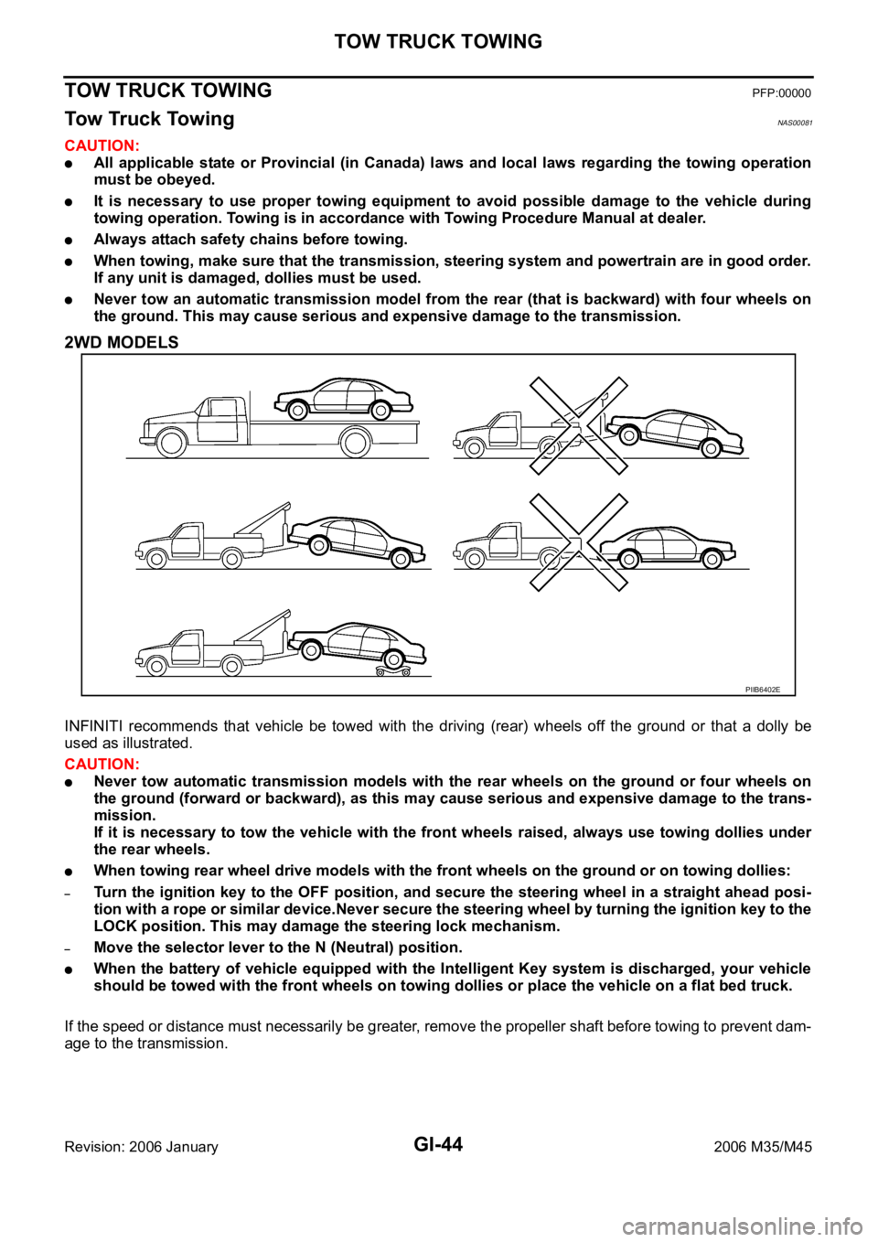
INFINITI recommends that vehicle be towed with the driving (rear) wheels off the ground or that a dolly be
used as illustrated.
CAUTION:
Never tow automatic transmission models with the rear wheels on the ground or four wheels on
the ground (forward or backward), as this may cause serious and expensive damage to the trans-
mission.
If it is necessary to tow the vehicle with the front wheels raised, always use towing dollies under
the rear wheels.
When towing rear wheel drive models with the front wheels on the ground or on towing dollies:
–Turn the ignition key to the OFF position, and secure the steering wheel in a straight ahead posi-
tion with a rope or similar device.Never secure the steering wheel by turning the ignition key to the
LOCK position. This may damage the steering lock mechanism.
–Move the selector lever to the N (Neutral) position.
When the battery of vehicle equipped with the Intelligent Key system is discharged, your vehicle
should be towed with the front wheels on towing dollies or place the vehicle on a flat bed truck.
If the speed or distance must necessarily be greater, remove the propeller shaft before towing to prevent dam-
age to the transmission.
PIIB6402E
Page 3516 of 5621

TERMINOLOGY
GI-53
C
D
E
F
G
H
I
J
K
L
MB
GI
Revision: 2006 January2006 M35/M45
TERMINOLOGYPFP:00011
SAE J1930 Terminology List NAS00088
All emission related terms used in this publication in accordance with SAE J1930 are listed. Accordingly, new
terms, new acronyms/abbreviations and old terms are listed in the following chart.
NEW TERMNEW ACRONYM /
ABBREVIATIONOLD TERM
Air cleaner ACL Air cleaner
Barometric pressure BARO ***
Barometric pressure sensor-BCDD BAROS-BCDD BCDD
Camshaft position CMP ***
Camshaft position sensor CMPS Crank angle sensor
Canister *** Canister
Carburetor CARB Carburetor
Charge air cooler CAC Intercooler
Closed loop CL Closed loop
Closed throttle position switch CTP switch Idle switch
Clutch pedal position switch CPP switch Clutch switch
Continuous fuel injection system CFI system ***
Continuous trap oxidizer system CTOX system ***
Crankshaft position CKP ***
Crankshaft position sensor CKPS ***
Data link connector DLC ***
Data link connector for CONSULT-II DLC for CONSULT-II Diagnostic connector for CONSULT-II
Diagnostic test mode DTM Diagnostic mode
Diagnostic test mode selector DTM selector Diagnostic mode selector
Diagnostic test mode I DTM I Mode I
Diagnostic test mode II DTM II Mode II
Diagnostic trouble code DTC Malfunction code
Direct fuel injection system DFI system ***
Distributor ignition system DI system Ignition timing control
Early fuel evaporation-mixture heater EFE-mixture heater Mixture heater
Early fuel evaporation system EFE system Mixture heater control
Electrically erasable programmable read
only memoryEEPROM ***
Electronic ignition system EI system Ignition timing control
Engine control EC ***
Engine control module ECM ECCS control unit
Engine coolant temperature ECT Engine temperature
Engine coolant temperature sensor ECTS Engine temperature sensor
Engine modification EM ***
Engine speed RPM Engine speed
Erasable programmable read only memory EPROM ***
Evaporative emission canister EVAP canister Canister
Evaporative emission system EVAP system Canister control solenoid valve
Exhaust gas recirculation valve EGR valve EGR valve
Page 3517 of 5621

GI-54
TERMINOLOGY
Revision: 2006 January2006 M35/M45
Exhaust gas recirculation control-BPT
valveEGRC-BPT valve BPT valve
Exhaust gas recirculation control-solenoid
valveEGRC-solenoid valve EGR control solenoid valve
Exhaust gas recirculation temperature sen-
sor
EGRT sensor Exhaust gas temperature sensor
EGR temperature sensor
Flash electrically erasable programmable
read only memoryFEEPROM ***
Flash erasable programmable read only
memoryFEPROM ***
Flexible fuel sensor FFS ***
Flexible fuel system FF system ***
Fuel pressure regulator *** Pressure regulator
Fuel pressure regulator control solenoid
valve*** PRVR control solenoid valve
Fuel trim FT ***
Heated Oxygen sensor HO2S Exhaust gas sensor
Idle air control system IAC system Idle speed control
Idle air control valve-air regulator IACV-air regulator Air regulator
Idle air control valve-auxiliary air control
valveIACV-AAC valve Auxiliary air control (AAC) valve
Idle air control valve-FICD solenoid valve IACV-FICD solenoid valve FICD solenoid valve
Idle air control valve-idle up control sole-
noid valveIACV-idle up control solenoid valve Idle up control solenoid valve
Idle speed control-FI pot ISC-FI pot FI pot
Idle speed control system ISC system ***
Ignition control IC ***
Ignition control module ICM ***
Indirect fuel injection system IFI system ***
Intake air IA Air
Intake air temperature sensor IAT sensor Air temperature sensor
Knock *** Detonation
Knock sensor KS Detonation sensor
Malfunction indicator lamp MIL Check engine light
Manifold absolute pressure MAP ***
Manifold absolute pressure sensor MAPS ***
Manifold differential pressure MDP ***
Manifold differential pressure sensor MDPS ***
Manifold surface temperature MST ***
Manifold surface temperature sensor MSTS ***
Manifold vacuum zone MVZ ***
Manifold vacuum zone sensor MVZS ***
Mass air flow sensor MAFS Air flow meter
Mixture control solenoid valve MC solenoid valve Air-fuel ratio control solenoid valve
Multiport fuel injection System MFI system Fuel injection controlNEW TERMNEW ACRONYM /
ABBREVIATIONOLD TERM
Page 3533 of 5621

GW-14
POWER WINDOW SYSTEM
Revision: 2006 January2006 M35/M45
to BCM terminal 42.
With ignition switch in ON or START position,
Power is supplied
through 15A fuse [No. 1, located in the fuse block (J/B)]
to BCM terminal 38, and
through BCM terminal 53
to power window main switch terminal 10
Ground supplied
to BCM terminal 52
through body grounds M16 and M70.
to power window main switch terminal 17
through body grounds M16 and M70.
to power window sub-switch (front passenger side) terminal 11
through body grounds M16 and M70.
to power window sub-switch (rear LH and RH) terminal 11
through body grounds B5, B40 and B131.
MANUAL OPERATION
Front Driver Side Door
WINDOW UP
When the front LH switch in the power window main switch is pressed in the up position,
Power is supplied
through power window main switch terminal 8
to power window motor (front driver side) terminal 2.
Ground is supplied
to power window motor (front driver side) terminal 1
through power window main switch terminal 11.
Then, the motor raises the window until the switch is released.
WINDOW DOWN
When the front LH switch in the power window main switch is pressed in the down position
Power is supplied
through power window main switch terminal 11
to power window motor (front driver side) terminal 1.
Ground is supplied
to power window motor (front driver side) terminal 2
through power window main switch terminal 8.
Then, the motor lowers the window until the switch is released.
Page 3535 of 5621

GW-16
POWER WINDOW SYSTEM
Revision: 2006 January2006 M35/M45
AUTO OPERATION
The power window AUTO feature enables the driver to open or close the window without holding the window
switch in the down or up position.
POWER WINDOW SERIAL LINK
Power window main switch, any power window sub-switches and BCM transmit and receive the signal by
power window serial link.
The under mentioned signal is transmitted from BCM to power window main switch and power window sub-
switches.
Keyless power window down signal.
The under mentioned signal is transmitted from power window main switch to power window sub-switch (front
passenger side)
Front passenger side door window operation signal.
Power window control by key cylinder switch signal.
Power window lock signal.
Retained power operation signal.
The under mentioned signal is transmitted from power window main switch to power window sub-switch (rear
LH or RH)
Rear LH or RH side door window operation signal.
Power window control by key cylinder switch signal.
Power window lock signal.
Retained power operation signal.
POWER WINDOW LOCK
The power window lock is designed to lock operation of all windows except for driver side door window.
When the lock position, the power window lock signal is transmitted to any power window sub-switches by
power window serial link. This prevents the power window motors from operating.
RETAINED POWER OPERATION
When the ignition switch is turned to the OFF position from ON or START position.
Power is supplied for 45 seconds
through BCM terminal 53
to power window main switch terminal 10.
When power and ground are supplied, the BCM continues to be energized, and the power window can be
operated.
The retained power operation is canceled when the driver or passenger side door is opened.
RAP signal period can be changed by CONSULT-II. Refer to GW-30, "
CONSULT-II Function (BCM)" .
Page 3536 of 5621

POWER WINDOW SYSTEM
GW-17
C
D
E
F
G
H
J
K
L
MA
B
GW
Revision: 2006 January2006 M35/M45
ANTI-PINCH SYSTEM
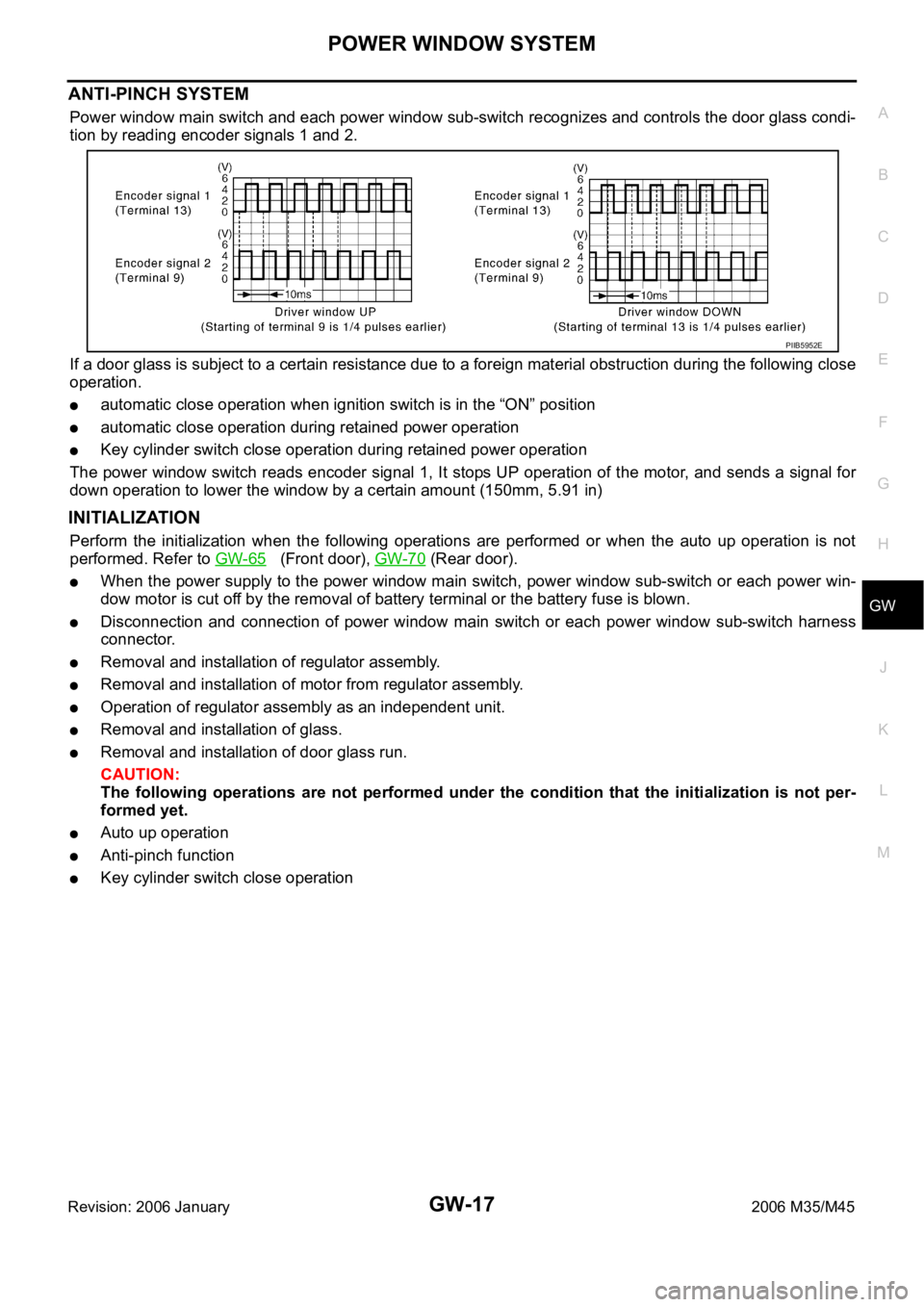
Power window main switch and each power window sub-switch recognizes and controls the door glass condi-
tion by reading encoder signals 1 and 2.
If a door glass is subject to a certain resistance due to a foreign material obstruction during the following close
operation.
automatic close operation when ignition switch is in the “ON” position
automatic close operation during retained power operation
Key cylinder switch close operation during retained power operation
The power window switch reads encoder signal 1, It stops UP operation of the motor, and sends a signal for
down operation to lower the window by a certain amount (150mm, 5.91 in)
INITIALIZATION
Perform the initialization when the following operations are performed or when the auto up operation is not
performed. Refer to GW-65
(Front door), GW-70 (Rear door).
When the power supply to the power window main switch, power window sub-switch or each power win-
dow motor is cut off by the removal of battery terminal or the battery fuse is blown.
Disconnection and connection of power window main switch or each power window sub-switch harness
connector.
Removal and installation of regulator assembly.
Removal and installation of motor from regulator assembly.
Operation of regulator assembly as an independent unit.
Removal and installation of glass.
Removal and installation of door glass run.
CAUTION:
The following operations are not performed under the condition that the initialization is not per-
formed yet.
Auto up operation
Anti-pinch function
Key cylinder switch close operation
PIIB5952E
Page 3537 of 5621

GW-18
POWER WINDOW SYSTEM
Revision: 2006 January2006 M35/M45
FAIL-SAFE CONTROL
The encoder signal detects the up / down speed / detection of door glass. If the malfunction is detected to the
encoder signal or the difference between the glass fully closed position (memorized in power window main
switch or power window sub-switch) and the actual glass position is detected, it shifts into the fail-safe control
It is shifts into the fail-safe control, the initialization is not performed and the following function is not activated
Auto up operation
Anti-pinch function
It is shifts into the fail-safe control, performed the initialization to resume normal operation condition.
POWER WINDOW CONTROL BY THE KEY CYLINDER SWITCH
When ignition key switch is OFF, front power window can be opened or closed by turning the key cylinder
switch UNLOCK / LOCK position more than 1.5 second over condition.
Power window can be opened as the door key cylinder is kept fully turning to the UNLOCK position.
Power window can be closed as the door key cylinder is kept fully turning to the LOCK position.
The power window DOWN stops when the following operations are carried out.
While performing open / close the window, power window is stopped at the position as the door key cylin-
der is placed on NEUTRAL.
When the ignition switch is turned ON while the power window DOWN is operated.
DTC Condition
Pulse sensor detects malfunctionDuring the glass opening/closing operation, a pulse signal is continuously
detected for the specified terms or more
Both pulse sensors detect malfunctionDuring the glass opening/closing operation, both pulse signals are not
detected for the specified values or more
Pulse direction malfunctionThe following condition is detected for the specified values or more. The
pulse signal (detected during glass open/close operation) detects the
opposite direction to the driving direction of power window motor.
Glass recognized position malfunction 1During the glass opening/closing operation, the difference between the
glass fully closed position (memorized in power window main switch or
power window sub-switch) and the actual glass position is detected for
the specified values or more.
Glass recognized position malfunction 2During the glass opening/closing operation, a pulse count is detected that
is above the glass full stroke
Glass fully closed position not updated malfunctionContinuously perform the glass open/close operation (with the glass not
fully closed) at the specified value (approx. 10 time) or more