Page 3546 of 5621
POWER WINDOW SYSTEM
GW-27
C
D
E
F
G
H
J
K
L
MA
B
GW
Revision: 2006 January2006 M35/M45
Terminal and Reference Value for BCMNIS0021L
Terminal Wire color Item ConditionVoltage [V]
(Approx.)
12 PFront door switch
passenger side signalON (Open) 0
OFF (Close) Battery voltage
22 G Power window serial link IGN SW ON or power window
timer operating.
38 W Ignition switch (ON or START) Ignition switch
(ON or START position)Battery voltage
39 L CAN - H — —
40 P CAN - L — —
42 P Power source (Fuse) — Battery voltage
52 B Ground — 0
53 BR Rap signalIGN SW ON Battery voltage
Within 45 second after ignition
switch is turned to OFFBattery voltage
When driver side or passenger
side door is opened daring
retained power operation0
54 O Power window power supply — Battery voltage
55 W Power source (Fusible link) — Battery voltage
62 VFront door switch
driver side signalON (Open) 0
OFF (Close) Battery voltage
PIIA2344J
Page 3547 of 5621
![INFINITI M35 2006 Factory Service Manual GW-28
POWER WINDOW SYSTEM
Revision: 2006 January2006 M35/M45
Terminal and Reference Value for Power Window Main SwitchNIS0021M
Terminal Wire color Item ConditionVoltage [V]
(Approx.)
2 W/B Encoder gro INFINITI M35 2006 Factory Service Manual GW-28
POWER WINDOW SYSTEM
Revision: 2006 January2006 M35/M45
Terminal and Reference Value for Power Window Main SwitchNIS0021M
Terminal Wire color Item ConditionVoltage [V]
(Approx.)
2 W/B Encoder gro](/manual-img/42/57023/w960_57023-3546.png)
GW-28
POWER WINDOW SYSTEM
Revision: 2006 January2006 M35/M45
Terminal and Reference Value for Power Window Main SwitchNIS0021M
Terminal Wire color Item ConditionVoltage [V]
(Approx.)
2 W/B Encoder ground — 0
4BRDoor key cylinder switch
LOCK signalKey position
(Neutral
Locked)5 0
6V/RDoor key cylinder switch
UNLOCK signalKey position
(Neutral
Unlocked)5 0
8LFront driver side power window
motor UP signalWhen front LH switch in
power window main switch is
UP at operated. Battery voltage
9 G/W Encoder pulse signal 2When power window motor oper-
ates.
10 Y/B Rap signalIGN SW ON Battery voltage
Within 45 second after ignition
switch is turned to OFFBattery voltage
When driver side or passenger
side door is opened daring
retained power operation0
11 GFront driver side power window
motor DOWN signalWhen front LH switch in
power window main switch is
DOWN at operated. Battery voltage
13 G/Y Encoder pulse signal 1When power window motor oper-
ates.
14 Y Power window serial linkIGN SW ON or power window
timer operating.
15 G/R Encoder power supplyWhen ignition switch ON or power
window timer operates.10
17 B Ground — 0
19 W/B Battery power supply — Battery voltage
OCC3383D
OCC3383D
PIIA2344J
Page 3548 of 5621
POWER WINDOW SYSTEM
GW-29
C
D
E
F
G
H
J
K
L
MA
B
GW
Revision: 2006 January2006 M35/M45
Terminal and Reference Value for (Front and Rear) Power Window Sub-SwitchNIS0021N
( ): Power window sub-switch (rear LH or RH)Terminal Wire color Item ConditionVoltage [V]
(Approx.)
3 W/B Encoder ground — 0
4 G/R Encoder power supplyWhen ignition switch ON or power
window timer operates10
8L
(G)Power window motor
UP signalWhen power window motor is
UP at operated. Battery voltage
9G
(L)Power window motor
DOWN signalWhen power window motor is
DOWN at operated.Battery voltage
10W/B
(W/R)Battery power supply — Battery voltage
11 B G r o u n d — 0
12 G/Y Encoder pulse signal 1When power window motor oper-
ates.
15 G/W Encoder pulse signal 2When power window motor oper-
ates.
16 Y Power window serial linkIGN SW ON or power window
timer operating.
OCC3383D
OCC3383D
PIIA2344J
Page 3549 of 5621
GW-30
POWER WINDOW SYSTEM
Revision: 2006 January2006 M35/M45
CONSULT-II Function (BCM)NIS0021O
CONSULT-II can display each diagnostic item using the diagnostic test modes shown following.
1. Turn ignition switch “ON”.
2. Connect “CONSULT-II and CONSULT-II CONVERTER” to the
data link connector (1).
3. Turn ignition switch “ON”.
4. Touch “START (NISSAN BASED VHCL)”.
5. Touch “BCM”.
If “BCM” is not indicated, go to Refer to GI-40
, “CONSULT-II
Date Link Connector (DLC) Circuit”
6. Touch “RETAINED PWR”.
BCM diagnostic test item Check item diagnostic test mode Content
RETAINED PWRWork support Changes setting of each function.
Data monitor Displays the input data of BCM in real time.
PBIB2712E
BCIA0029E
BCIA0030E
LIIA0163E
Page 3550 of 5621
POWER WINDOW SYSTEM
GW-31
C
D
E
F
G
H
J
K
L
MA
B
GW
Revision: 2006 January2006 M35/M45
7. Select diagnosis mode.
“ACTIVE TEST”, “WORK SUPPORT” and “DATA MONITOR”
are available.
WORK SUPPORT
DATE MONITOR
BCIA0031E
Work item Description
RETAINED PWRRap signal’s power supply period can be changed by mode setting. Selects rap signal’s power
supply period between three steps
MODE1 (45 sec.) / MODE2 (OFF) / MODE 3 (2 min.).
Work item Description
IGN ON SW Indicates (ON / OFF) condition of ignition switch
DOOR SW–DR Indicates (ON / OFF) condition of front door switch driver side
DOOR SW–AS Indicates (ON / OFF) condition of front door switch passenger side
Page 3553 of 5621
![INFINITI M35 2006 Factory Service Manual GW-34
POWER WINDOW SYSTEM
Revision: 2006 January2006 M35/M45
BCM Power Supply and Ground Circuit CheckNIS0021R
1. CHECK FUSE
Check 15A fuse [No. 1, located in fuse block (J/B)]
Check 10A fuse [No. 21, INFINITI M35 2006 Factory Service Manual GW-34
POWER WINDOW SYSTEM
Revision: 2006 January2006 M35/M45
BCM Power Supply and Ground Circuit CheckNIS0021R
1. CHECK FUSE
Check 15A fuse [No. 1, located in fuse block (J/B)]
Check 10A fuse [No. 21,](/manual-img/42/57023/w960_57023-3552.png)
GW-34
POWER WINDOW SYSTEM
Revision: 2006 January2006 M35/M45
BCM Power Supply and Ground Circuit CheckNIS0021R
1. CHECK FUSE
Check 15A fuse [No. 1, located in fuse block (J/B)]
Check 10A fuse [No. 21, located in fuse block (J/B)]
Check 50A fusible link (letter F , located in the fuse and fusible link box).
NOTE:
Refer to GW-13, "
Component Parts and Harness Connector Location" .
OK or NG
OK >> GO TO 2.
NG >> If fuse is blown out, be sure to eliminate cause of malfunction before installing new fuse. Refer to
PG-3, "
POWER SUPPLY ROUTING CIRCUIT" .
2. CHECK POWER SUPPLY CIRCUIT
Check voltage between BCM connector and ground.
OK or NG
OK >> GO TO 3.
NG >> Check BCM power supply circuit for open or short.
3. CHECK GROUND CIRCUIT
1. Turn ignition switch OFF.
2. Disconnect BCM connector.
3. Check continuity between BCM connector and ground.
OK or NG
OK >> Power supply and ground circuit are OK.
NG >> Check BCM ground circuit for open or short.
Te r m i n a l s
Condition of
ignition switchVoltage (V)
(Approx.) (+)
(–)
BCM connector Terminal
M1 38
GroundON
Battery voltage
M242
OFF
55
PIIB5934E
BCM connector Terminal
GroundContinuity
M2 52 Yes
PIIB5935E
Page 3554 of 5621

POWER WINDOW SYSTEM
GW-35
C
D
E
F
G
H
J
K
L
MA
B
GW
Revision: 2006 January2006 M35/M45
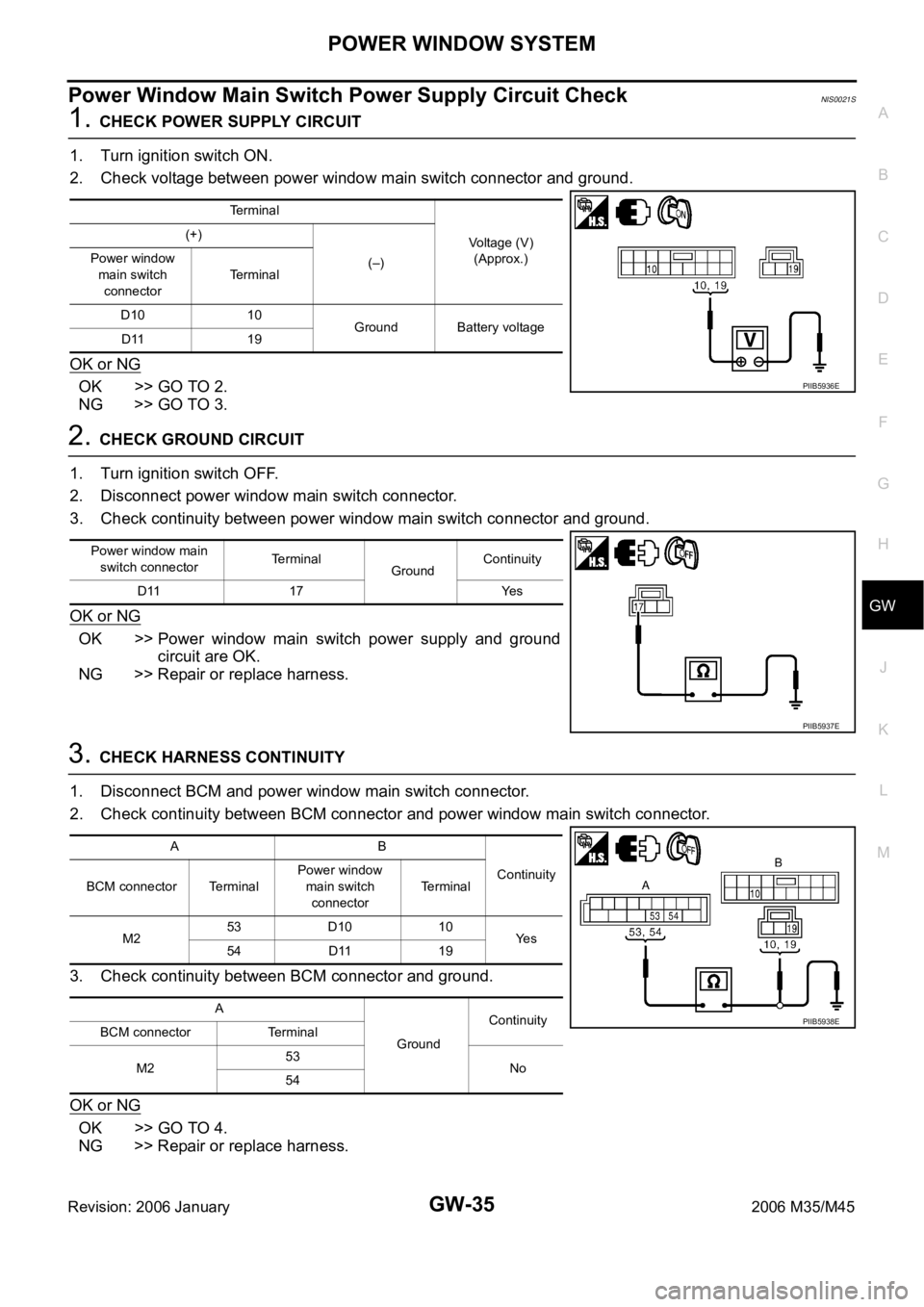
Power Window Main Switch Power Supply Circuit Check NIS0021S
1. CHECK POWER SUPPLY CIRCUIT
1. Turn ignition switch ON.
2. Check voltage between power window main switch connector and ground.
OK or NG
OK >> GO TO 2.
NG >> GO TO 3.
2. CHECK GROUND CIRCUIT
1. Turn ignition switch OFF.
2. Disconnect power window main switch connector.
3. Check continuity between power window main switch connector and ground.
OK or NG
OK >> Power window main switch power supply and ground
circuit are OK.
NG >> Repair or replace harness.
3. CHECK HARNESS CONTINUITY
1. Disconnect BCM and power window main switch connector.
2. Check continuity between BCM connector and power window main switch connector.
3. Check continuity between BCM connector and ground.
OK or NG
OK >> GO TO 4.
NG >> Repair or replace harness.
Terminal
Voltage (V)
(Approx.) (+)
(–) Power window
main switch
connectorTerminal
D10 10
Ground Battery voltage
D11 19
PIIB5936E
Power window main
switch connectorTerminal
GroundContinuity
D11 17 Yes
PIIB5937E
AB
Continuity
BCM connector TerminalPower window
main switch
connectorTerminal
M253 D10 10
Ye s
54 D11 19
A
GroundContinuity
BCM connector Terminal
M253
No
54
PIIB5938E
Page 3555 of 5621

GW-36
POWER WINDOW SYSTEM
Revision: 2006 January2006 M35/M45
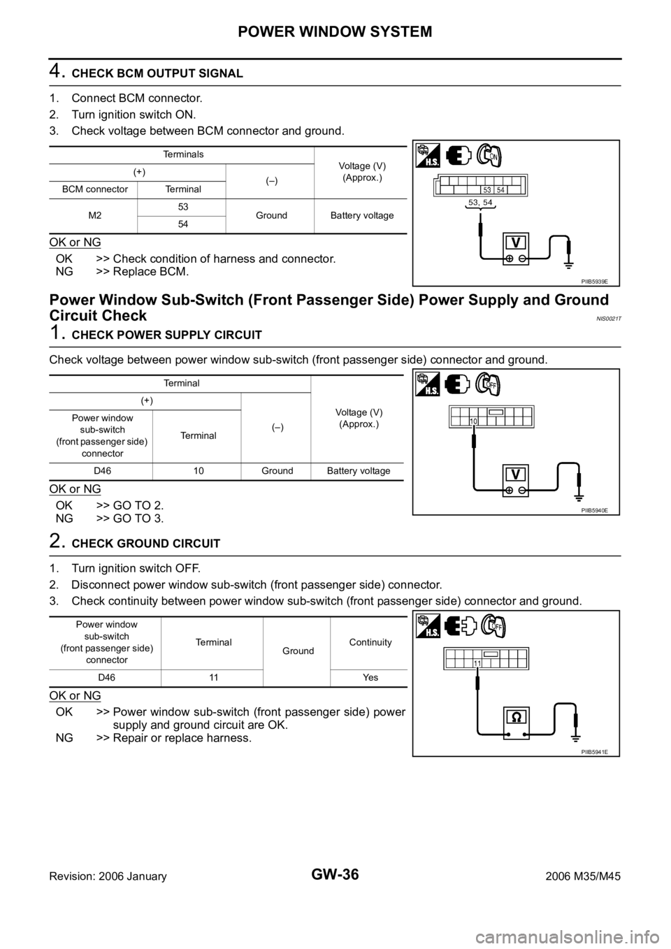
4. CHECK BCM OUTPUT SIGNAL
1. Connect BCM connector.
2. Turn ignition switch ON.
3. Check voltage between BCM connector and ground.
OK or NG
OK >> Check condition of harness and connector.
NG >> Replace BCM.
Power Window Sub-Switch (Front Passenger Side) Power Supply and Ground
Circuit Check
NIS0021T
1. CHECK POWER SUPPLY CIRCUIT
Check voltage between power window sub-switch (front passenger side) connector and ground.
OK or NG
OK >> GO TO 2.
NG >> GO TO 3.
2. CHECK GROUND CIRCUIT
1. Turn ignition switch OFF.
2. Disconnect power window sub-switch (front passenger side) connector.
3. Check continuity between power window sub-switch (front passenger side) connector and ground.
OK or NG
OK >> Power window sub-switch (front passenger side) power
supply and ground circuit are OK.
NG >> Repair or replace harness.
Terminals
Voltage (V)
(Approx.) (+)
(–)
BCM connector Terminal
M253
Ground Battery voltage
54
PIIB5939E
Terminal
Voltage (V)
(Approx.) (+)
(–) Power window
sub-switch
(front passenger side)
connectorTerminal
D46 10 Ground Battery voltage
PIIB5940E
Power window
sub-switch
(front passenger side)
connectorTerminal
GroundContinuity
D46 11 Yes
PIIB5941E