Page 3564 of 5621
POWER WINDOW SYSTEM
GW-45
C
D
E
F
G
H
J
K
L
MA
B
GW
Revision: 2006 January2006 M35/M45
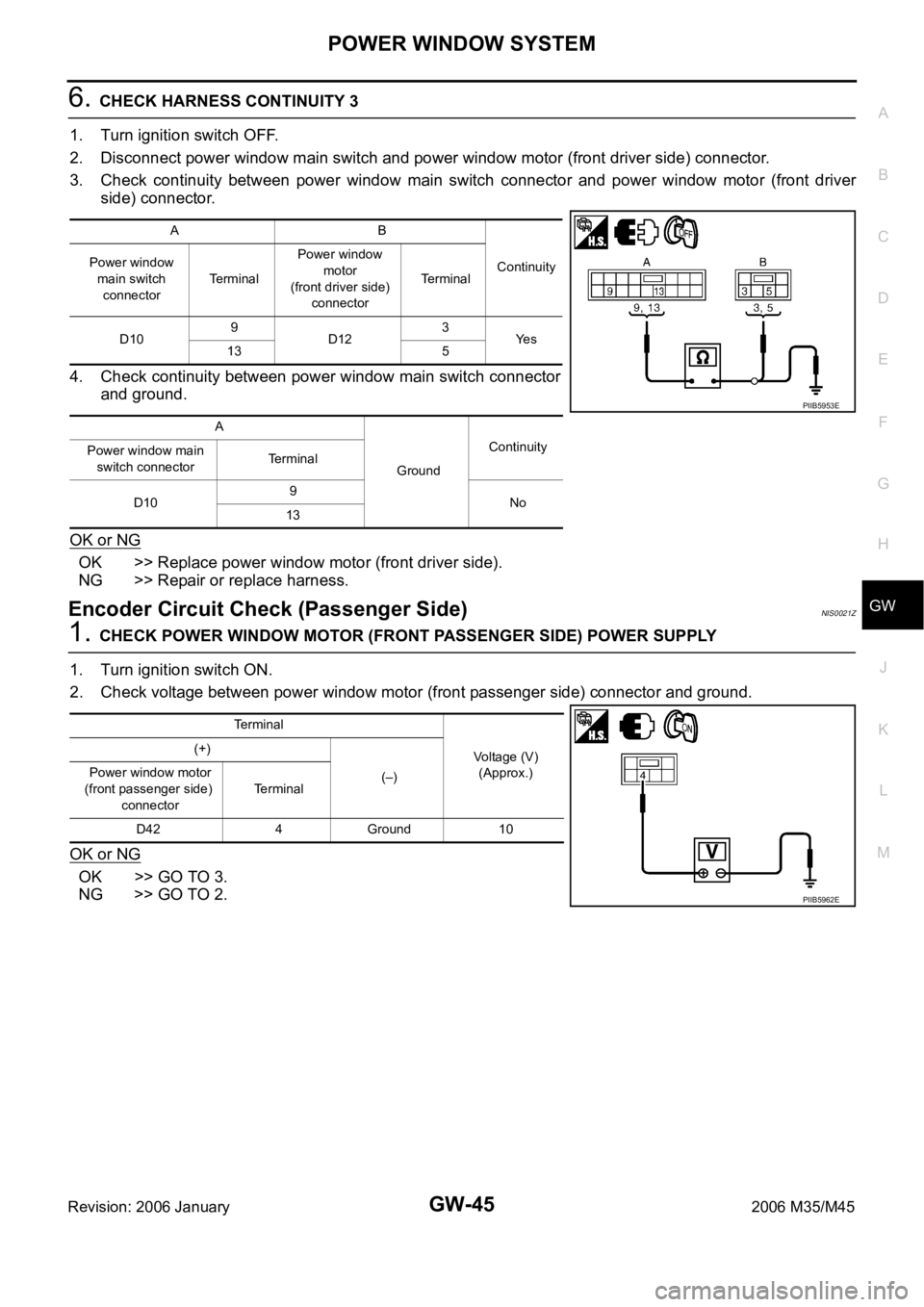
6. CHECK HARNESS CONTINUITY 3
1. Turn ignition switch OFF.
2. Disconnect power window main switch and power window motor (front driver side) connector.
3. Check continuity between power window main switch connector and power window motor (front driver
side) connector.
4. Check continuity between power window main switch connector
and ground.
OK or NG
OK >> Replace power window motor (front driver side).
NG >> Repair or replace harness.
Encoder Circuit Check (Passenger Side)NIS0021Z
1. CHECK POWER WINDOW MOTOR (FRONT PASSENGER SIDE) POWER SUPPLY
1. Turn ignition switch ON.
2. Check voltage between power window motor (front passenger side) connector and ground.
OK or NG
OK >> GO TO 3.
NG >> GO TO 2.
AB
Continuity Power window
main switch
connectorTerminalPower window
motor
(front driver side)
connectorTerminal
D109
D123
Ye s
13 5
A
GroundContinuity
Power window main
switch connectorTerminal
D109
No
13
PIIB5953E
Terminal
Voltage (V)
(Approx.) (+)
(–) Power window motor
(front passenger side)
connectorTerminal
D42 4 Ground 10
PIIB5962E
Page 3565 of 5621
GW-46
POWER WINDOW SYSTEM
Revision: 2006 January2006 M35/M45
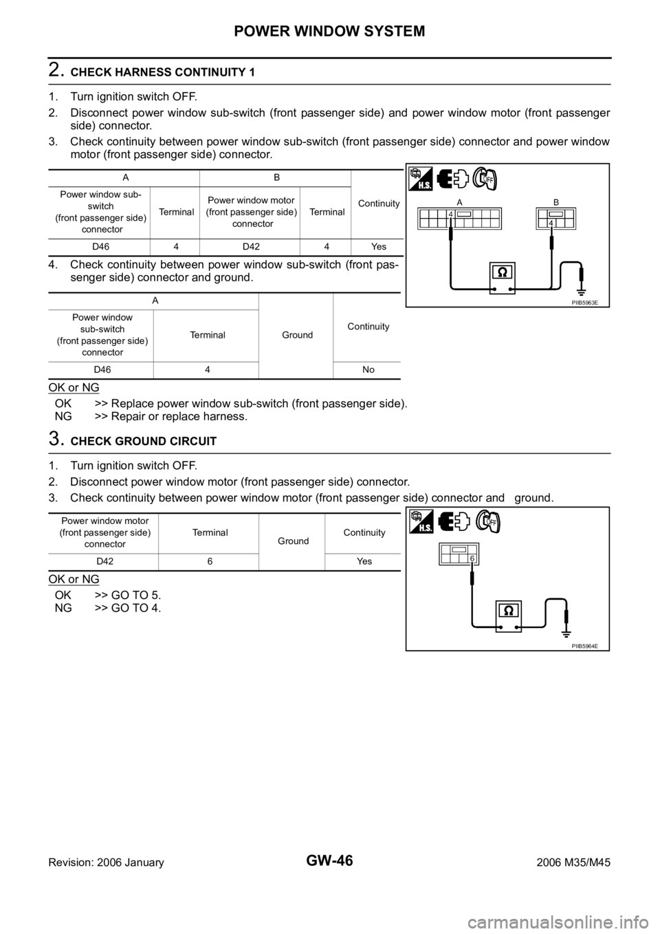
2. CHECK HARNESS CONTINUITY 1
1. Turn ignition switch OFF.
2. Disconnect power window sub-switch (front passenger side) and power window motor (front passenger
side) connector.
3. Check continuity between power window sub-switch (front passenger side) connector and power window
motor (front passenger side) connector.
4. Check continuity between power window sub-switch (front pas-
senger side) connector and ground.
OK or NG
OK >> Replace power window sub-switch (front passenger side).
NG >> Repair or replace harness.
3. CHECK GROUND CIRCUIT
1. Turn ignition switch OFF.
2. Disconnect power window motor (front passenger side) connector.
3. Check continuity between power window motor (front passenger side) connector and ground.
OK or NG
OK >> GO TO 5.
NG >> GO TO 4.
AB
Continuity Power window sub-
switch
(front passenger side)
connectorTe r m i n a lPower window motor
(front passenger side)
connectorTerminal
D46 4 D42 4 Yes
A
GroundContinuity Power window
sub-switch
(front passenger side)
connectorTerminal
D46 4 No
PIIB5963E
Power window motor
(front passenger side)
connectorTerminal
GroundContinuity
D42 6 Yes
PIIB5964E
Page 3566 of 5621
POWER WINDOW SYSTEM
GW-47
C
D
E
F
G
H
J
K
L
MA
B
GW
Revision: 2006 January2006 M35/M45
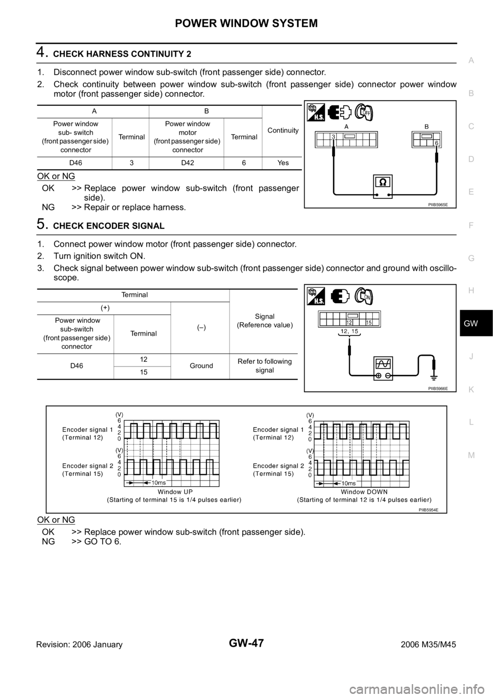
4. CHECK HARNESS CONTINUITY 2
1. Disconnect power window sub-switch (front passenger side) connector.
2. Check continuity between power window sub-switch (front passenger side) connector power window
motor (front passenger side) connector.
OK or NG
OK >> Replace power window sub-switch (front passenger
side).
NG >> Repair or replace harness.
5. CHECK ENCODER SIGNAL
1. Connect power window motor (front passenger side) connector.
2. Turn ignition switch ON.
3. Check signal between power window sub-switch (front passenger side) connector and ground with oscillo-
scope.
OK or NG
OK >> Replace power window sub-switch (front passenger side).
NG >> GO TO 6.
AB
Continuity Power window
sub- switch
(front passenger side)
connectorTerminalPower window
motor
(front passenger side)
connectorTe r m i n a l
D463D42 6Yes
PIIB5965E
Terminal
Signal
(Reference value) (+)
(–) Power window
sub-switch
(front passenger side)
connectorTerminal
D4612
GroundRefer to following
signal
15
PIIB5966E
PIIB5954E
Page 3567 of 5621
GW-48
POWER WINDOW SYSTEM
Revision: 2006 January2006 M35/M45
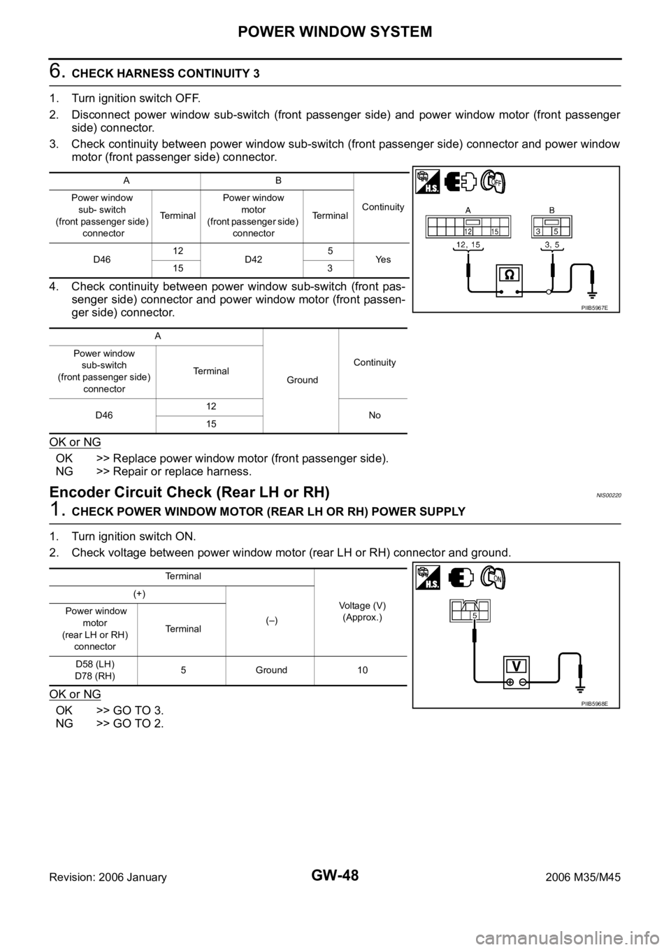
6. CHECK HARNESS CONTINUITY 3
1. Turn ignition switch OFF.
2. Disconnect power window sub-switch (front passenger side) and power window motor (front passenger
side) connector.
3. Check continuity between power window sub-switch (front passenger side) connector and power window
motor (front passenger side) connector.
4. Check continuity between power window sub-switch (front pas-
senger side) connector and power window motor (front passen-
ger side) connector.
OK or NG
OK >> Replace power window motor (front passenger side).
NG >> Repair or replace harness.
Encoder Circuit Check (Rear LH or RH)NIS00220
1. CHECK POWER WINDOW MOTOR (REAR LH OR RH) POWER SUPPLY
1. Turn ignition switch ON.
2. Check voltage between power window motor (rear LH or RH) connector and ground.
OK or NG
OK >> GO TO 3.
NG >> GO TO 2.
AB
Continuity Power window
sub- switch
(front passenger side)
connectorTerminalPower window
motor
(front passenger side)
connectorTerminal
D4612
D425
Ye s
15 3
A
GroundContinuity Power window
sub-switch
(front passenger side)
connectorTerminal
D4612
No
15
PIIB5967E
Terminal
Voltage (V)
(Approx.) (+)
(–) Power window
motor
(rear LH or RH)
connectorTerminal
D58 (LH)
D78 (RH)5 Ground 10
PIIB5968E
Page 3568 of 5621
POWER WINDOW SYSTEM
GW-49
C
D
E
F
G
H
J
K
L
MA
B
GW
Revision: 2006 January2006 M35/M45
2. CHECK HARNESS CONTINUITY 1
1. Turn ignition switch OFF.
2. Disconnect power window sub-switch (rear LH or RH) and power window motor (rear LH or RH) connec-
tor.
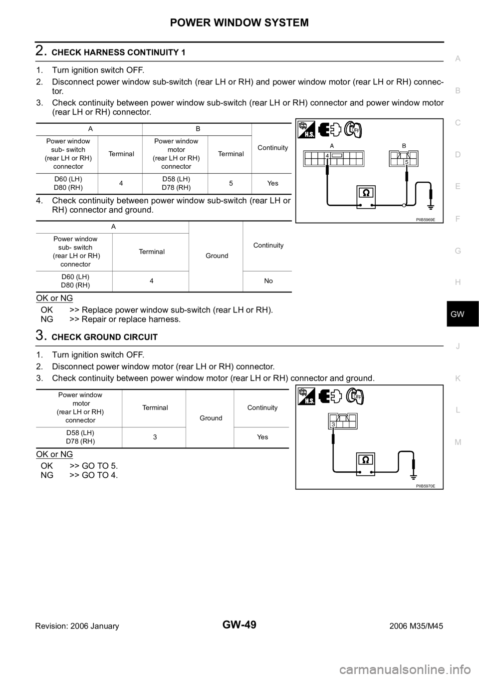
3. Check continuity between power window sub-switch (rear LH or RH) connector and power window motor
(rear LH or RH) connector.
4. Check continuity between power window sub-switch (rear LH or
RH) connector and ground.
OK or NG
OK >> Replace power window sub-switch (rear LH or RH).
NG >> Repair or replace harness.
3. CHECK GROUND CIRCUIT
1. Turn ignition switch OFF.
2. Disconnect power window motor (rear LH or RH) connector.
3. Check continuity between power window motor (rear LH or RH) connector and ground.
OK or NG
OK >> GO TO 5.
NG >> GO TO 4.
AB
Continuity Power window
sub- switch
(rear LH or RH)
connectorTerminalPower window
motor
(rear LH or RH)
connectorTerminal
D60 (LH)
D80 (RH)4D58 (LH)
D78 (RH)5Yes
A
GroundContinuity Power window
sub- switch
(rear LH or RH)
connectorTerminal
D60 (LH)
D80 (RH)4No
PIIB5969E
Power window
motor
(rear LH or RH)
connectorTe r m i n a l
GroundContinuity
D58 (LH)
D78 (RH)3Yes
PIIB5970E
Page 3569 of 5621
GW-50
POWER WINDOW SYSTEM
Revision: 2006 January2006 M35/M45
4. CHECK HARNESS CONTINUITY 2
1. Disconnect power window sub-switch (rear LH or RH) connector.
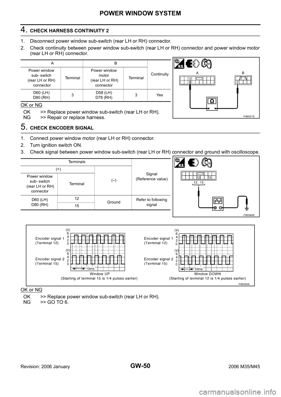
2. Check continuity between power window sub-switch (rear LH or RH) connector and power window motor
(rear LH or RH) connector.
OK or NG
OK >> Replace power window sub-switch (rear LH or RH).
NG >> Repair or replace harness.
5. CHECK ENCODER SIGNAL
1. Connect power window motor (rear LH or RH) connector.
2. Turn ignition switch ON.
3. Check signal between power window sub-switch (rear LH or RH) connector and ground with oscilloscope.
OK or NG
OK >> Replace power window sub-switch (rear LH or RH).
NG >> GO TO 6.
AB
Continuity Power window
sub- switch
(rear LH or RH)
connectorTerminalPower window
motor
(rear LH or RH)
connectorTerminal
D60 (LH)
D80 (RH)3D58 (LH)
D78 (RH)3Yes
PIIB5971E
Terminals
Signal
(Reference value) (+)
(–) Power window
sub- switch
(rear LH or RH)
connectorTerminal
D60 (LH)
D80 (RH)12
GroundRefer to following
signal
15
PIIB5966E
PIIB5954E
Page 3570 of 5621
POWER WINDOW SYSTEM
GW-51
C
D
E
F
G
H
J
K
L
MA
B
GW
Revision: 2006 January2006 M35/M45
6. CHECK HARNESS CONTINUITY 3
1. Turn ignition switch OFF.
2. Disconnect power window sub-switch (rear LH or RH) and power window motor (rear LH or RH) connec-
tor.
3. Check continuity between power window sub-switch (rear LH or RH) connector and power window motor
(rear LH or RH) connector.
4. Check power window sub-switch (rear LH or RH) connector and
ground.
OK or NG
OK >> Replace power window motor (rear LH or RH).
NG >> Repair or replace harness.
AB
Continuity Power window
sub- switch
(rear LH or RH)
connectorTerminalPower window
motor
(rear LH or RH)
connectorTerminal
D60 (LH)
D80 (RH)12
D58 (LH)
D78 (RH)4
Ye s
15 6
A
GroundContinuity Power window
sub- switch
(rear LH or RH)
connectorTerminal
D60 (LH)
D80 (RH)12
No
15
PIIB5972E
Page 3572 of 5621
POWER WINDOW SYSTEM
GW-53
C
D
E
F
G
H
J
K
L
MA
B
GW
Revision: 2006 January2006 M35/M45
2. CHECK HARNESS CONTINUITY
1. Turn ignition switch OFF.
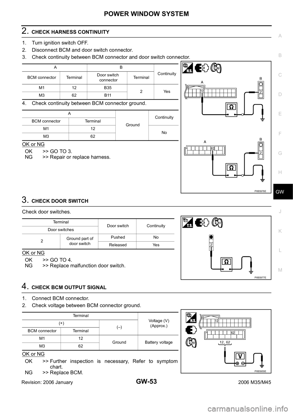
2. Disconnect BCM and door switch connector.
3. Check continuity between BCM connector and door switch connector.
4. Check continuity between BCM connector ground.
OK or NG
OK >> GO TO 3.
NG >> Repair or replace harness.
3. CHECK DOOR SWITCH
Check door switches.
OK or NG
OK >> GO TO 4.
NG >> Replace malfunction door switch.
4. CHECK BCM OUTPUT SIGNAL
1. Connect BCM connector.
2. Check voltage between BCM connector ground.
OK or NG
OK >> Further inspection is necessary, Refer to symptom
chart.
NG >> Replace BCM.
AB
Continuity
BCM connector TerminalDoor switch
connectorTerminal
M1 12 B35
2Yes
M3 62 B11
A
GroundContinuity
BCM connector Terminal
M1 12
No
M3 62
PIIB5976E
Terminal
Door switch Continuity
Door switches
2Ground part of
door switchPushed No
Released Yes
PIIB5977E
Terminal
Voltage (V)
(Approx.) (+)
(–)
BCM connector Terminal
M1 12
Ground Battery voltage
M3 62
PIIB5955E