2006 INFINITI M35 ignition
[x] Cancel search: ignitionPage 3468 of 5621
PRECAUTIONS
GI-5
C
D
E
F
G
H
I
J
K
L
MB
GI
Revision: 2006 January2006 M35/M45
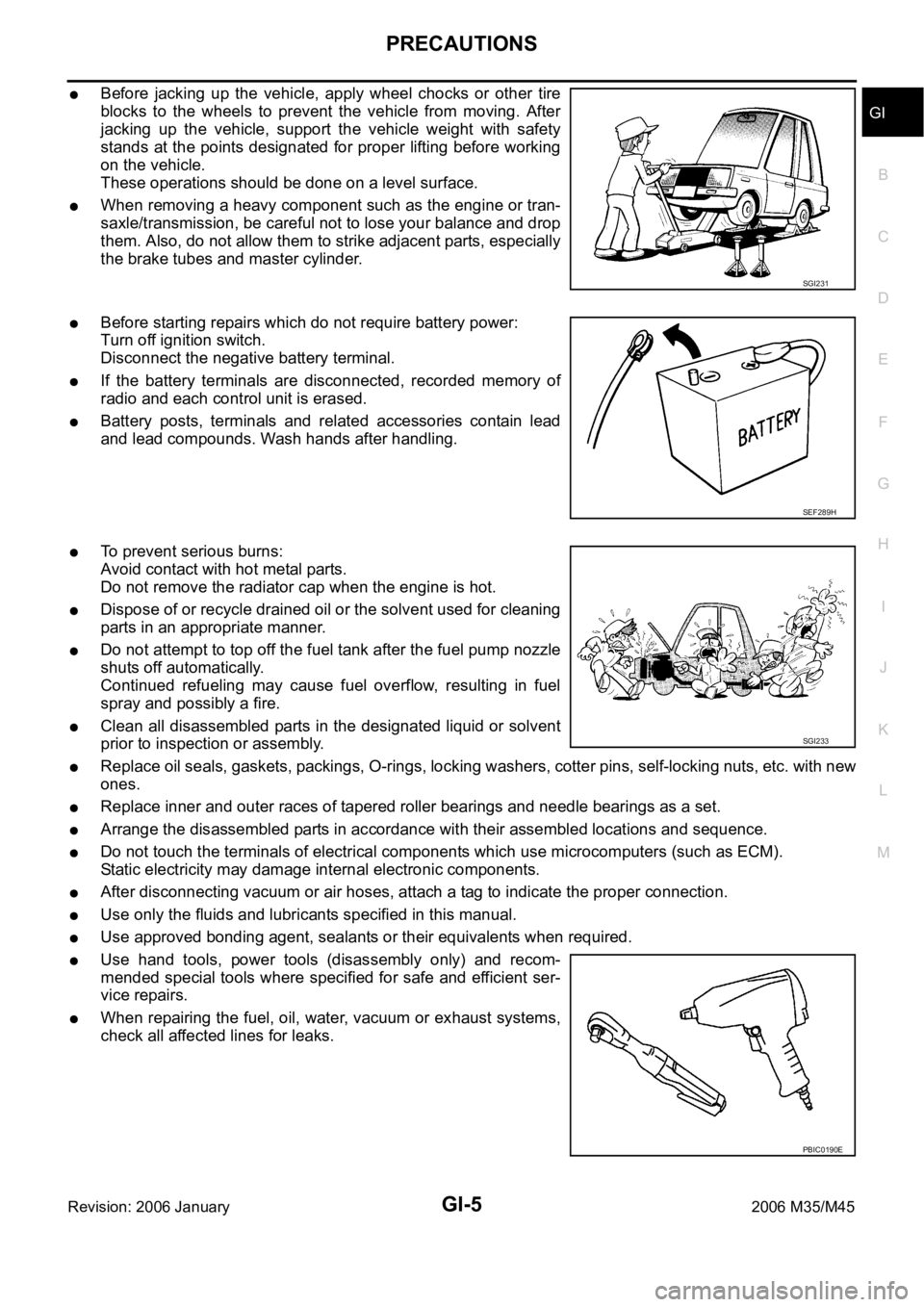
Before jacking up the vehicle, apply wheel chocks or other tire
blocks to the wheels to prevent the vehicle from moving. After
jacking up the vehicle, support the vehicle weight with safety
stands at the points designated for proper lifting before working
on the vehicle.
These operations should be done on a level surface.
When removing a heavy component such as the engine or tran-
saxle/transmission, be careful not to lose your balance and drop
them. Also, do not allow them to strike adjacent parts, especially
the brake tubes and master cylinder.
Before starting repairs which do not require battery power:
Turn off ignition switch.
Disconnect the negative battery terminal.
If the battery terminals are disconnected, recorded memory of
radio and each control unit is erased.
Battery posts, terminals and related accessories contain lead
and lead compounds. Wash hands after handling.
To prevent serious burns:
Avoid contact with hot metal parts.
Do not remove the radiator cap when the engine is hot.
Dispose of or recycle drained oil or the solvent used for cleaning
parts in an appropriate manner.
Do not attempt to top off the fuel tank after the fuel pump nozzle
shuts off automatically.
Continued refueling may cause fuel overflow, resulting in fuel
spray and possibly a fire.
Clean all disassembled parts in the designated liquid or solvent
prior to inspection or assembly.
Replace oil seals, gaskets, packings, O-rings, locking washers, cotter pins, self-locking nuts, etc. with new
ones.
Replace inner and outer races of tapered roller bearings and needle bearings as a set.
Arrange the disassembled parts in accordance with their assembled locations and sequence.
Do not touch the terminals of electrical components which use microcomputers (such as ECM).
Static electricity may damage internal electronic components.
After disconnecting vacuum or air hoses, attach a tag to indicate the proper connection.
Use only the fluids and lubricants specified in this manual.
Use approved bonding agent, sealants or their equivalents when required.
Use hand tools, power tools (disassembly only) and recom-
mended special tools where specified for safe and efficient ser-
vice repairs.
When repairing the fuel, oil, water, vacuum or exhaust systems,
check all affected lines for leaks.
SGI231
SEF289H
SGI233
PBIC0190E
Page 3469 of 5621
GI-6
PRECAUTIONS
Revision: 2006 January2006 M35/M45
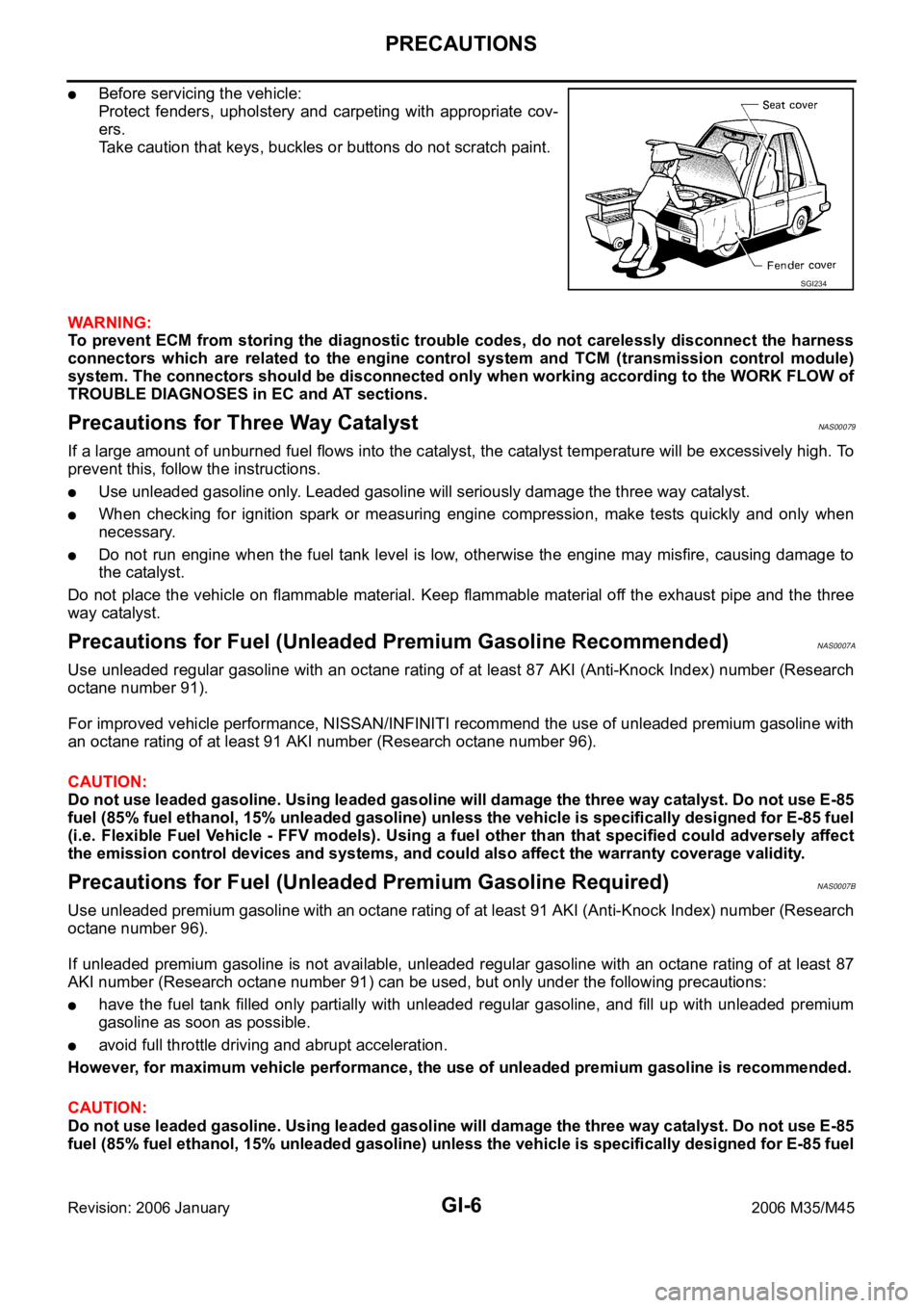
Before servicing the vehicle:
Protect fenders, upholstery and carpeting with appropriate cov-
ers.
Take caution that keys, buckles or buttons do not scratch paint.
WAR NING :
To prevent ECM from storing the diagnostic trouble codes, do not carelessly disconnect the harness
connectors which are related to the engine control system and TCM (transmission control module)
system. The connectors should be disconnected only when working according to the WORK FLOW of
TROUBLE DIAGNOSES in EC and AT sections.
Precautions for Three Way CatalystNAS00079
If a large amount of unburned fuel flows into the catalyst, the catalyst temperature will be excessively high. To
prevent this, follow the instructions.
Use unleaded gasoline only. Leaded gasoline will seriously damage the three way catalyst.
When checking for ignition spark or measuring engine compression, make tests quickly and only when
necessary.
Do not run engine when the fuel tank level is low, otherwise the engine may misfire, causing damage to
the catalyst.
Do not place the vehicle on flammable material. Keep flammable material off the exhaust pipe and the three
way catalyst.
Precautions for Fuel (Unleaded Premium Gasoline Recommended)NAS0007A
Use unleaded regular gasoline with an octane rating of at least 87 AKI (Anti-Knock Index) number (Research
octane number 91).
For improved vehicle performance, NISSAN/INFINITI recommend the use of unleaded premium gasoline with
an octane rating of at least 91 AKI number (Research octane number 96).
CAUTION:
Do not use leaded gasoline. Using leaded gasoline will damage the three way catalyst. Do not use E-85
fuel (85% fuel ethanol, 15% unleaded gasoline) unless the vehicle is specifically designed for E-85 fuel
(i.e. Flexible Fuel Vehicle - FFV models). Using a fuel other than that specified could adversely affect
the emission control devices and systems, and could also affect the warranty coverage validity.
Precautions for Fuel (Unleaded Premium Gasoline Required)NAS0007B
Use unleaded premium gasoline with an octane rating of at least 91 AKI (Anti-Knock Index) number (Research
octane number 96).
If unleaded premium gasoline is not available, unleaded regular gasoline with an octane rating of at least 87
AKI number (Research octane number 91) can be used, but only under the following precautions:
have the fuel tank filled only partially with unleaded regular gasoline, and fill up with unleaded premium
gasoline as soon as possible.
avoid full throttle driving and abrupt acceleration.
However, for maximum vehicle performance, the use of unleaded premium gasoline is recommended.
CAUTION:
Do not use leaded gasoline. Using leaded gasoline will damage the three way catalyst. Do not use E-85
fuel (85% fuel ethanol, 15% unleaded gasoline) unless the vehicle is specifically designed for E-85 fuel
SGI234
Page 3470 of 5621
PRECAUTIONS
GI-7
C
D
E
F
G
H
I
J
K
L
MB
GI
Revision: 2006 January2006 M35/M45
(i.e. Flexible Fuel Vehicle - FFV models). Using a fuel other than that specified could adversely affect
the emission control devices and systems, and could also affect the warranty coverage validity.
Precautions for Multiport Fuel Injection System or Engine Control SystemNAS0007C
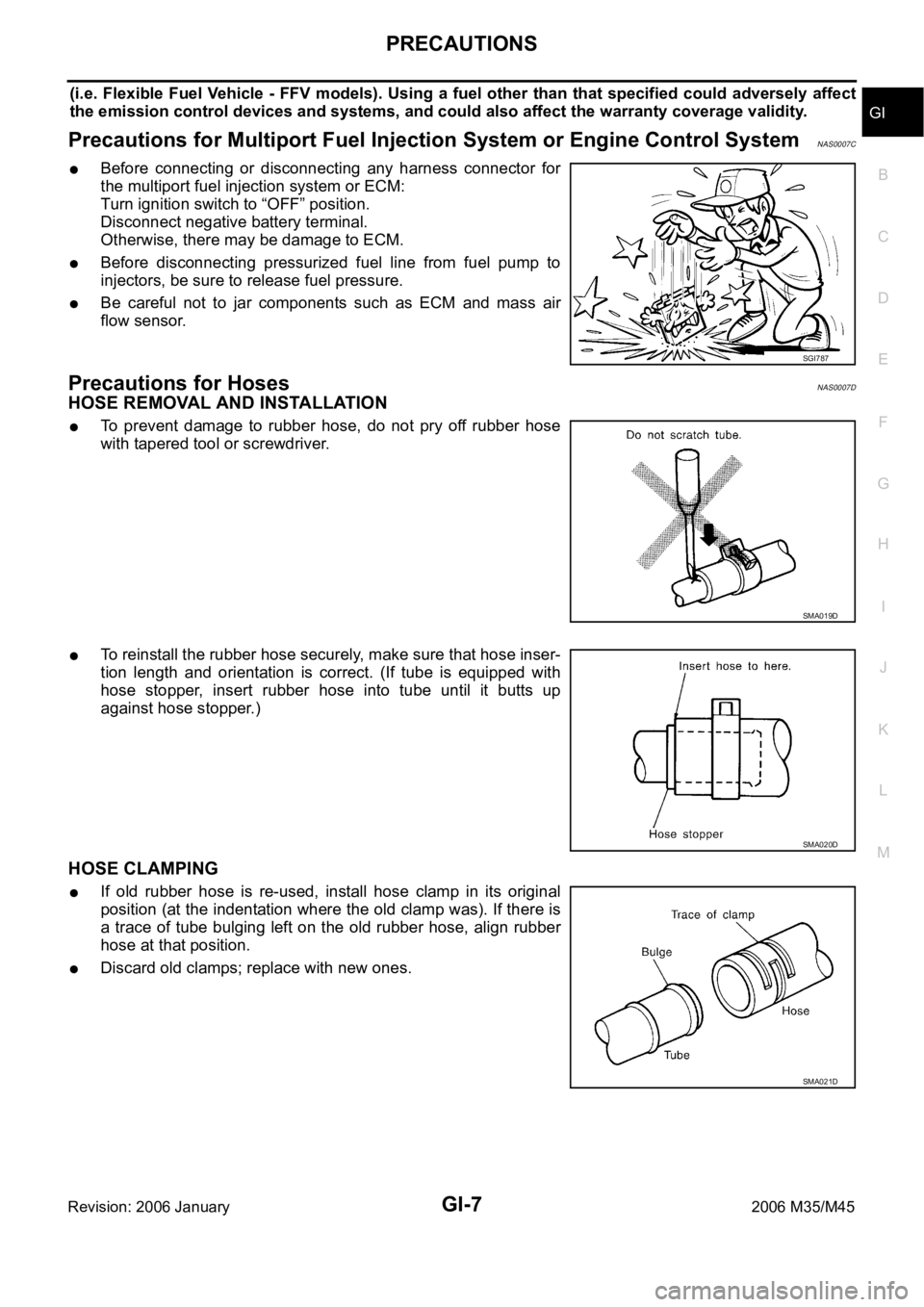
Before connecting or disconnecting any harness connector for
the multiport fuel injection system or ECM:
Turn ignition switch to “OFF” position.
Disconnect negative battery terminal.
Otherwise, there may be damage to ECM.
Before disconnecting pressurized fuel line from fuel pump to
injectors, be sure to release fuel pressure.
Be careful not to jar components such as ECM and mass air
flow sensor.
Precautions for HosesNAS0007D
HOSE REMOVAL AND INSTALLATION
To prevent damage to rubber hose, do not pry off rubber hose
with tapered tool or screwdriver.
To reinstall the rubber hose securely, make sure that hose inser-
tion length and orientation is correct. (If tube is equipped with
hose stopper, insert rubber hose into tube until it butts up
against hose stopper.)
HOSE CLAMPING
If old rubber hose is re-used, install hose clamp in its original
position (at the indentation where the old clamp was). If there is
a trace of tube bulging left on the old rubber hose, align rubber
hose at that position.
Discard old clamps; replace with new ones.
SGI787
SMA019D
SMA020D
SMA021D
Page 3475 of 5621
GI-12
HOW TO USE THIS MANUAL
Revision: 2006 January2006 M35/M45
How to Follow Trouble DiagnosesNAS0007M
DESCRIPTION
NOTICE:
Trouble diagnoses indicate work procedures required to diagnose problems effectively. Observe the following
instructions before diagnosing.
1.Before performing trouble diagnoses, read the “Preliminary Check”, the “Symptom Chart” or the
“Work Flow”.
2.After repairs, re-check that the problem has been completely eliminated.
3.Refer to Component Parts and Harness Connector Location for the Systems described in each
section for identification/location of components and harness connectors.
4.Refer to the Circuit Diagram for quick pinpoint check.
If you need to check circuit continuity between harness connectors in more detail, such as when a
sub-harness is used, refer to Wiring Diagram in each individual section and Harness Layout in PG
section for identification of harness connectors.
5.When checking circuit continuity, ignition switch should be OFF.
6.Before checking voltage at connectors, check battery voltage.
7.After accomplishing the Diagnostic Procedures and Electrical Components Inspection, make sure
that all harness connectors are reconnected as they were.
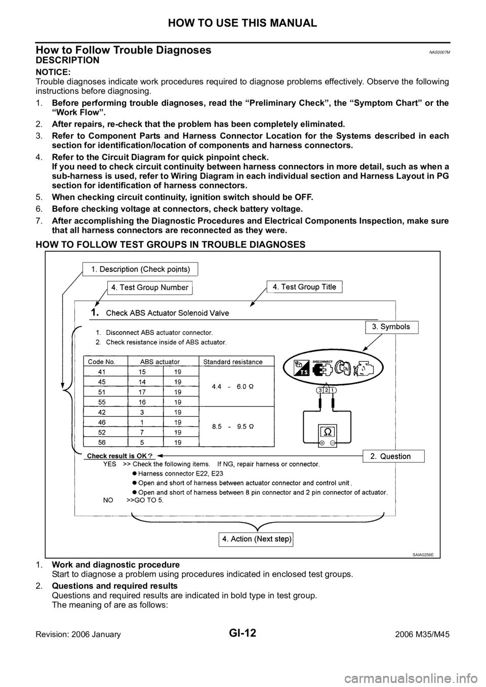
HOW TO FOLLOW TEST GROUPS IN TROUBLE DIAGNOSES
1.Work and diagnostic procedure
Start to diagnose a problem using procedures indicated in enclosed test groups.
2.Questions and required results
Questions and required results are indicated in bold type in test group.
The meaning of are as follows:
SAIA0256E
Page 3483 of 5621
GI-20
HOW TO USE THIS MANUAL
Revision: 2006 January2006 M35/M45
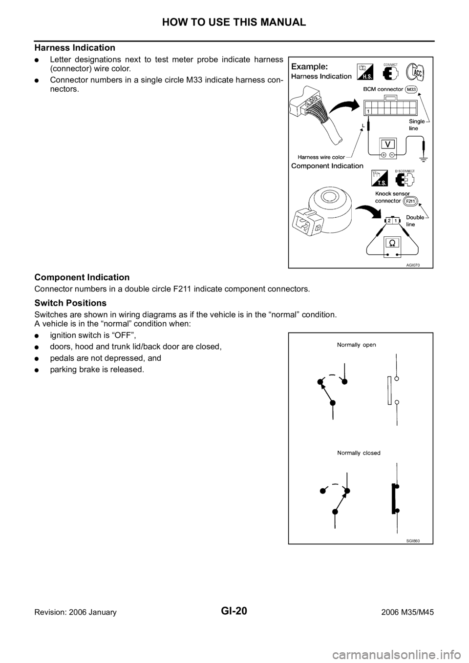
Harness Indication
Letter designations next to test meter probe indicate harness
(connector) wire color.
Connector numbers in a single circle M33 indicate harness con-
nectors.
Component Indication
Connector numbers in a double circle F211 indicate component connectors.
Switch Positions
Switches are shown in wiring diagrams as if the vehicle is in the “normal” condition.
A vehicle is in the “normal” condition when:
ignition switch is “OFF”,
doors, hood and trunk lid/back door are closed,
pedals are not depressed, and
parking brake is released.
AGI070
SGI860
Page 3495 of 5621
GI-32
SERVICE INFORMATION FOR ELECTRICAL INCIDENT
Revision: 2006 January2006 M35/M45
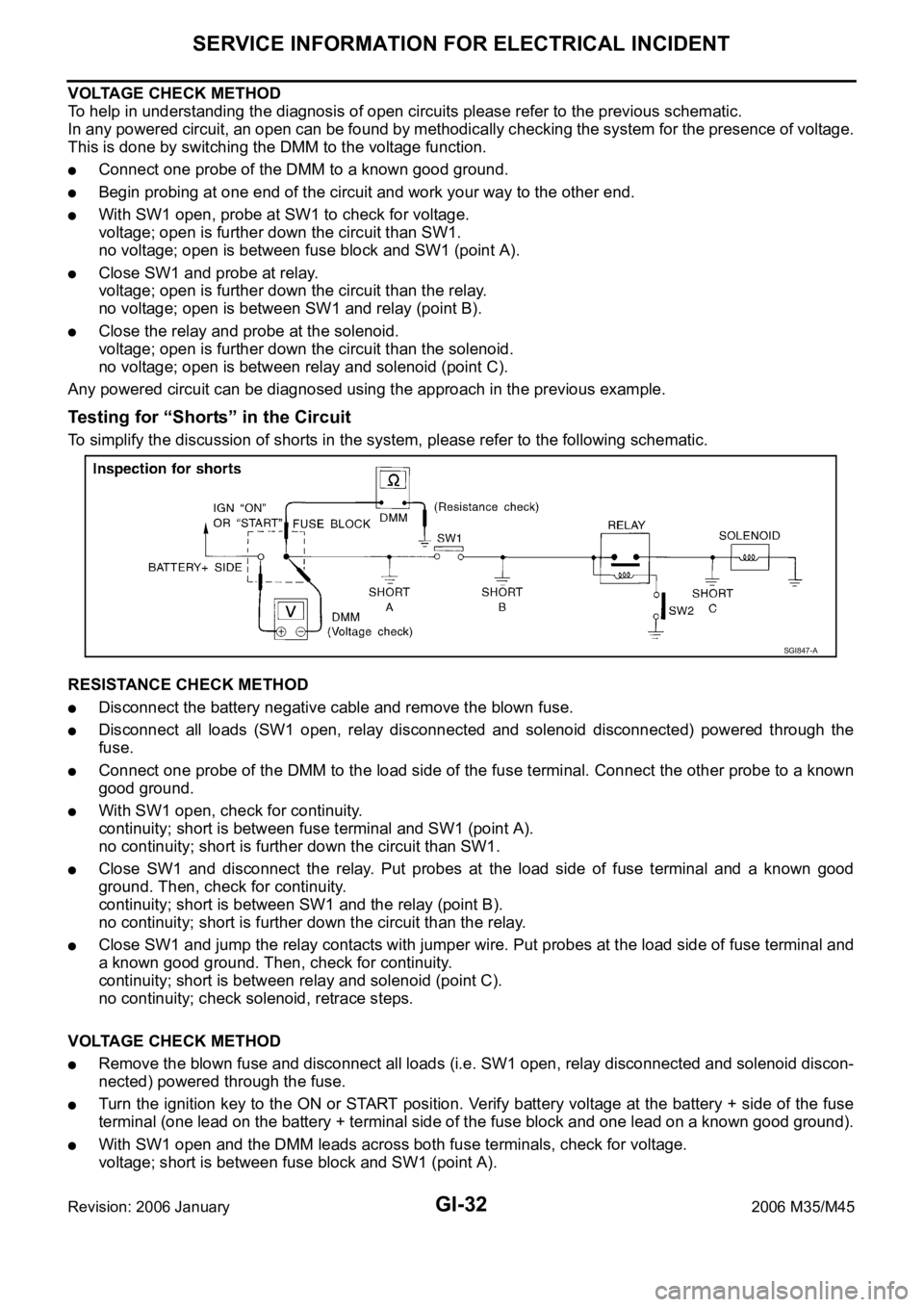
VOLTAGE CHECK METHOD
To help in understanding the diagnosis of open circuits please refer to the previous schematic.
In any powered circuit, an open can be found by methodically checking the system for the presence of voltage.
This is done by switching the DMM to the voltage function.
Connect one probe of the DMM to a known good ground.
Begin probing at one end of the circuit and work your way to the other end.
With SW1 open, probe at SW1 to check for voltage.
voltage; open is further down the circuit than SW1.
no voltage; open is between fuse block and SW1 (point A).
Close SW1 and probe at relay.
voltage; open is further down the circuit than the relay.
no voltage; open is between SW1 and relay (point B).
Close the relay and probe at the solenoid.
voltage; open is further down the circuit than the solenoid.
no voltage; open is between relay and solenoid (point C).
Any powered circuit can be diagnosed using the approach in the previous example.
Testing for “Shorts” in the Circuit
To simplify the discussion of shorts in the system, please refer to the following schematic.
RESISTANCE CHECK METHOD
Disconnect the battery negative cable and remove the blown fuse.
Disconnect all loads (SW1 open, relay disconnected and solenoid disconnected) powered through the
fuse.
Connect one probe of the DMM to the load side of the fuse terminal. Connect the other probe to a known
good ground.
With SW1 open, check for continuity.
continuity; short is between fuse terminal and SW1 (point A).
no continuity; short is further down the circuit than SW1.
Close SW1 and disconnect the relay. Put probes at the load side of fuse terminal and a known good
ground. Then, check for continuity.
continuity; short is between SW1 and the relay (point B).
no continuity; short is further down the circuit than the relay.
Close SW1 and jump the relay contacts with jumper wire. Put probes at the load side of fuse terminal and
a known good ground. Then, check for continuity.
continuity; short is between relay and solenoid (point C).
no continuity; check solenoid, retrace steps.
VOLTAGE CHECK METHOD
Remove the blown fuse and disconnect all loads (i.e. SW1 open, relay disconnected and solenoid discon-
nected) powered through the fuse.
Turn the ignition key to the ON or START position. Verify battery voltage at the battery + side of the fuse
terminal (one lead on the battery + terminal side of the fuse block and one lead on a known good ground).
With SW1 open and the DMM leads across both fuse terminals, check for voltage.
voltage; short is between fuse block and SW1 (point A).
SGI847-A
Page 3501 of 5621

GI-38
CONSULT-II CHECKING SYSTEM
Revision: 2006 January2006 M35/M45
CONSULT-II CHECKING SYSTEMPFP:00000
DescriptionNAS0007S
CONSULT-II is a hand-held type tester. When it is connected with a diagnostic connector equipped on the
vehicle side, it will communicate with the control unit equipped in the vehicle and then enable various
kinds of diagnostic tests.
Refer to “CONSULT-II Software Operation Manual” for more information.
Function and System Application NAS0007T
x: Applicable
*: NISSAN Anti-Theft System (INFINITI/NISSAN Vehicle Immobilizer System) Diagnostic test
modeFunction
ENGINE
A/T
AIR BAG
METER A/C AMP
BCM
AUTO DRIVE POS.
ABS (Including VDC)
NATS (IVIS/NATS) *
IPDM E/R
ICC
ALL MODE AWD/4WD
INTELLIGENT KEY
LDW
AIR PRESSURE MONITOR
RAS/HICAS
ADAPTIVE LIGHT
PRECRASH SEATBELT
MULTI AV
Work supportThis mode enables a technician to adjust
some devices faster and more accurately by
following the indications on CONSULT-II.x - - - xxx -- x- xxx- x- -
Self-diagnostic
resultsSelf-diagnostic results can be read and
erased quickly.xxxxxxxxxxxxxxxxxx
Trouble diagnos-
tic recordCurrent self-diagnostic results and all trouble
diagnostic records previously stored can be
read.--x---------------
Data monitor Input/Output data in the ECU can be read. x x - x x x x - x xxxxxxxxx
CAN diagnosis
support monitorThe condition of CAN communication line
can be read.xx- xxxx- xxxxxxxxxx
Active testDiagnostic Test Mode in which CONSULT-II
drives some actuators apart from the ECUs
and also shifts some parameters in a speci-
fied range.x- - - xxx -xxxxxxxx- -
DTC & SRT con-
firmationThe results of SRT (System Readiness Test)
and the self-diagnosis status/result can be
confirmed.x- ----------------
DTC work sup-
portThe operating condition to confirm Diagnosis
Trouble Codes can be selected.xx----------------
ECU (ECM/TCM)
part numberECU (ECM/TCM) part number can be read. xx - - xxx -- xxxxxxxxx
ECU discrimi-
nated No.Classification number of a replacement ECU
can be read to prevent an incorrect ECU from
being installed.-- x---------------
Function testThis mode can show results of self-diagnosis
of ECU with either 'OK' or 'NG'. For engines,
more practical tests regarding sensors/
switches and/or actuators are available.xxx---x-----------
Control unit ini-
tializationAll registered ignition key IDs in NATS com-
ponents can be initialized and new IDs can
be registered.-- -----x----------
AV COMM moni-
torThe condition of AV communication can be
Indicated.------------ ---- -x
Page 3502 of 5621
CONSULT-II CHECKING SYSTEM
GI-39
C
D
E
F
G
H
I
J
K
L
MB
GI
Revision: 2006 January2006 M35/M45
Nickel Metal Hydride Battery Replacement NAS0007U
CONSULT-II contains a nickel metal hydride battery. When replacing the battery obey the following:
WAR NING :
Replace the nickel metal hydride battery with Genuine CONSULT-II battery only. Use of another bat-
tery may present a risk of fire or explosion. The battery may present a fire or chemical burn hazard if
mistreated. Do not recharge, disassemble or dispose of in fire.
Keep the battery out of reach of children and discard used battery conforming to the local regulations.
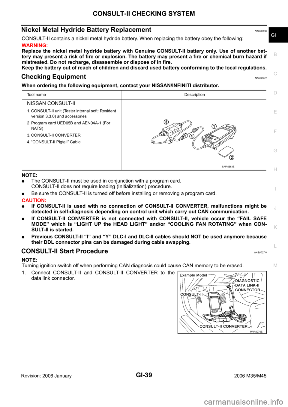
Checking Equipment NAS0007V
When ordering the following equipment, contact your NISSAN/INFINITI distributor.
NOTE:
The CONSULT-II must be used in conjunction with a program card.
CONSULT-II does not require loading (Initialization) procedure.
Be sure the CONSULT-II is turned off before installing or removing a program card.
CAUTION:
If CONSULT-II is used with no connection of CONSULT-II CONVERTER, malfunctions might be
detected in self-diagnosis depending on control unit which carry out CAN communication.
If CONSULT-II CONVERTER is not connected with CONSULT-II, vehicle occur the “FAIL SAFE
MODE” which is “LIGHT UP the HEAD LIGHT” and/or “COOLING FAN ROTAT I N G ” w h e n C O N -
SULT-II is started.
Previous CONSULT-II “I” and “Y” DLC-I and DLC-II cables should NOT be used anymore because
their DDL connector pins can be damaged during cable swapping.
CONSULT-II Start ProcedureNAS0007W
NOTE:
Turning ignition switch off when performing CAN diagnosis could cause CAN memory to be erased.
1. Connect CONSULT-II and CONSULT-II CONVERTER to the
data link connector.
Tool nameDescription
NISSAN CONSULT-II
1. CONSULT-II unit (Tester internal soft: Resident
version 3.3.0) and accessories
2. Program card UED05B and AEN04A-1 (For
NATS)
3. CONSULT-II CONVERTER
4. “CONSULT-II Pigtail” Cable
SAIA0363E
PAIA0070E