2006 INFINITI M35 ground
[x] Cancel search: groundPage 5172 of 5621
CHARGING SYSTEM
SC-35
C
D
E
F
G
H
I
J
L
MA
B
SC
Revision: 2006 January2006 M35/M45
Power Generation Voltage Variable Control System Operation InspectionNKS003NQ
CAUTION:
For this model, the battery current sensor that is installed to the battery cable at the negative ter-
minal measures the charging/discharging current of the battery, and performs various controls. If
the electrical component or the ground wire is connected directly to the battery terminal, the cur-
rent other than that being measured with the battery current sensor is charging to or discharging
from the battery. This condition causes the malfunction of the control, and then the battery dis-
charge may occur. Never connect the electrical component or the ground wire directly to the bat-
tery terminal.
When performing this inspection, always use the charged battery that completed the battery
inspection. (When the charging rate of the battery is low, the response speed of the voltage
change will become slow. This is a cause of an incorrect inspection.)
INSPECTION PROCEDURE
1. CHECK ECM (CONSULT-II)
Perform ECM self-diagnosis with CONSULT-II. Refer to EC-133, "
CONSULT-II Function (ENGINE)"
(VQ35DE) or EC-846, "CONSULT-II Function (ENGINE)" (VK45DE).
Self
-diagnostic results content
No malfunction detected>> GO TO 2.
Malfunction detected>> Check applicable parts, and repair or replace corresponding parts.
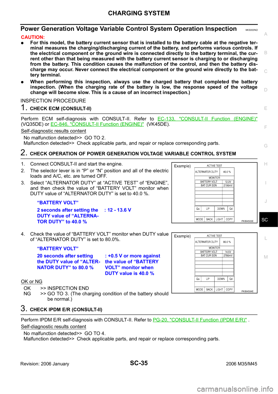
2. CHECK OPERATION OF POWER GENERATION VOLTAGE VARIABLE CONTROL SYSTEM
1. Connect CONSULT-II and start the engine.
2. The selector lever is in “P” or “N” position and all of the electric
loads and A/C, etc. are turned OFF.
3. Select “ALTERNATOR DUTY” at “ACTIVE TEST” of “ENGINE”,
and then check the value of “BATTERY VOLT” monitor when
DUTY value of “ALTERNATOR DUTY” is set to 40.0 %.
4. Check the value of “BATTERY VOLT” monitor when DUTY value
of “ALTERNATOR DUTY” is set to 80.0%.
OK or NG
OK >> INSPECTION END
NG >> GO TO 3. (The charging condition of the battery should
be normal.)
3. CHECK IPDM E/R (CONSULT-II)
Perform IPDM E/R self-diagnosis with CONSULT-II. Refer to PG-20, "
CONSULT-II Function (IPDM E/R)" .
Self
-diagnostic results content
No malfunction detected>> GO TO 4.
Malfunction detected>> Check applicable parts, and repair or replace corresponding parts. “BATTERY VOLT”
2 seconds after setting the
DUTY value of “ALTERNA-
TOR DUTY” to 40.0 %: 12 - 13.6 V
PKIB4503E
“BATTERY VOLT”
20 seconds after setting
the DUTY value of “ALTER-
NATOR DUTY” to 80.0 %: +0.5 V or more against
the value of “BATTERY
VOLT” monitor when
DUTY value is 40.0 %
PKIB4504E
Page 5173 of 5621
SC-36
CHARGING SYSTEM
Revision: 2006 January2006 M35/M45
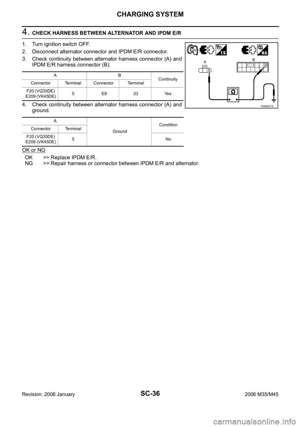
4. CHECK HARNESS BETWEEN ALTERNATOR AND IPDM E/R
1. Turn ignition switch OFF.
2. Disconnect alternator connector and IPDM E/R connector.
3. Check continuity between alternator harness connector (A) and
IPDM E/R harness connector (B).
4. Check continuity between alternator harness connector (A) and
ground.
OK or NG
OK >> Replace IPDM E/R.
NG >> Repair harness or connector between IPDM E/R and alternator.
AB
Continuity
Connector Terminal Connector Terminal
F20 (VQ35DE)
E209 (VK45DE)5 E8 33 Yes
A
GroundCondition
Connector Terminal
F20 (VQ35DE)
E209 (VK45DE)5No
PKIB8811E
Page 5176 of 5621
CHARGING SYSTEM
SC-39
C
D
E
F
G
H
I
J
L
MA
B
SC
Revision: 2006 January2006 M35/M45
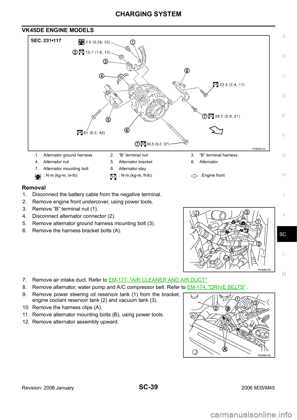
VK45DE ENGINE MODELS
Removal
1. Disconnect the battery cable from the negative terminal.
2. Remove engine front undercover, using power tools.
3. Remove “B” terminal nut (1).
4. Disconnect alternator connector (2).
5. Remove alternator ground harness mounting bolt (3).
6. Remove the harness bracket bolts (A).
7. Remove air intake duct. Refer to EM-177, "
AIR CLEANER AND AIR DUCT" .
8. Remove alternator, water pump and A/C compressor belt. Refer to EM-174, "
DRIVE BELTS" .
9. Remove power steering oil reservoir tank (1) from the bracket,
engine coolant reservoir tank (2) and vacuum tank (3).
10. Remove the harness clips (A).
11. Remove alternator mounting bolts (B), using power tools.
12. Remove alternator assembly upward.
1. Alternator ground harness 2. “B” terminal nut 3. “B” terminal harness
4. Alternator nut 5. Alternator bracket 6. Alternator
7. Alternator mounting bolt 8. Alternator stay
: Nꞏm (kg-m, in-lb) : Nꞏm (kg-m, ft-lb) : Engine front
PKIB8812E
PKIB8813E
PKIB8814E
Page 5180 of 5621
SERVICE DATA AND SPECIFICATIONS (SDS)
SC-43
C
D
E
F
G
H
I
J
L
MA
B
SC
Revision: 2006 January2006 M35/M45
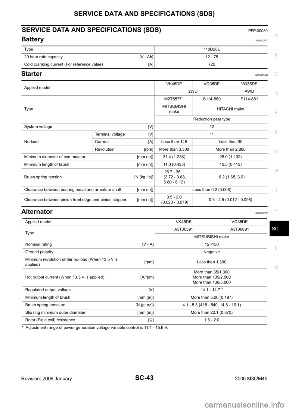
SERVICE DATA AND SPECIFICATIONS (SDS)PFP:00030
BatteryNKS003NT
StarterNKS003NU
AlternatorNKS003NV
*: Adjustment range of power generation voltage variable control is 11.4 - 15.6 V. Ty p e110D26L
20 hour rate capacity [V - Ah] 12 - 75
Cold cranking current (For reference value) [A] 720
Applied modelVK45DE VQ35DE VQ35DE
2WD AWD
Ty p eM2T85771 S114-880 S114-881
MITSUBISHI
makeHITACHI make
Reduction gear type
System voltage [V] 12
No-loadTerminal voltage [V] 11
Current [A] Less than 145 Less than 90
Revolution [rpm] More than 3,300 More than 2,880
Minimum diameter of commutator [mm (in)] 31.4 (1.236) 28.0 (1.102)
Minimum length of brush [mm (in)] 11.0 (0.433) 10.5 (0.413)
Brush spring tension [N (kg, lb)]26.7 - 36.1
(2.72 - 3.68,
6.80 - 8.12)16.2 (1.65, 3.6)
Clearance between bearing metal and armature shaft [mm (in)] Less than 0.2 (0.008)
Clearance between pinion front edge and pinion stopper [mm (in)]0.5 - 2.0
(0.020 - 0.079)0.3 - 2.5 (0.012 - 0.098)
Applied model VK45DE VQ35DE
Ty p eA3TJ0591 A3TJ0691
MITSUBISHI make
Nominal rating [V - A] 12 -150
Ground polarityNegative
Minimum revolution under no-load (When 13.5 V is
applied)[rpm] Less than 1,300
Hot output current (When 13.5 V is applied) [A/rpm]More than 35/1,300
More than 105/2,500
More than 136/5,000
Regulated output voltage [V] 14.1 - 14.7 *
Minimum length of brush [mm (in)] More than 5.00 (0.197)
Brush spring pressure [N (g, oz)] 4.1 - 5.3 (418 - 540, 14.8 - 19.1)
Slip ring minimum outer diameter [mm (in)] More than 22.1 (0.870)
Rotor (Field coil) resistance [
] 1.6 - 2.0
Page 5182 of 5621
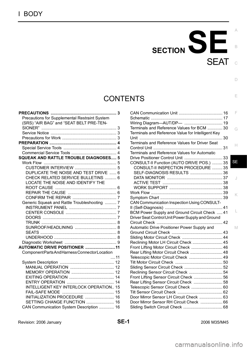
SE-1
SEAT
I BODY
CONTENTS
C
D
E
F
G
H
J
K
L
M
SECTION SE
A
B
SE
Revision: 2006 January2006 M35/M45
SEAT
PRECAUTIONS .......................................................... 3
Precautions for Supplemental Restraint System
(SRS) “AIR BAG” and “SEAT BELT PRE-TEN-
SIONER” .................................................................. 3
Service Notice .......................................................... 3
Precautions for Work ...........................................
..... 3
PREPARATION ........................................................... 4
Special Service Tools ............................................... 4
Commercial Service Tools ........................................ 4
SQUEAK AND RATTLE TROUBLE DIAGNOSES ..... 5
Work Flow ................................................................ 5
CUSTOMER INTERVIEW ..................................... 5
DUPLICATE THE NOISE AND TEST DRIVE ....... 6
CHECK RELATED SERVICE BULLETINS ........... 6
LOCATE THE NOISE AND IDENTIFY THE
ROOT CAUSE ...................................................... 6
REPAIR THE CAUSE ........................................... 6
CONFIRM THE REPAIR ....................................... 7
Generic Squeak and Rattle Troubleshooting ........... 7
INSTRUMENT PANEL .......................................... 7
CENTER CONSOLE ............................................. 7
DOORS ................................................................. 7
TRUNK .................................................................. 8
SUNROOF/HEADLINING ..................................... 8
SEATS ................................................................... 8
UNDERHOOD ....................................................... 8
Diagnostic Worksheet .............................................. 9
AUTOMATIC DRIVE POSITIONER ...........................11
Component Parts And Harness Connector Location
.... 11
System Description ................................................ 12
MANUAL OPERATION ....................................... 12
MEMORY OPERATION ...................................... 12
EXITING OPERATION ........................................ 14
ENTRY OPERATION .......................................... 14
INTELLIGENT KEY INTERLOCK OPERATION ... 15
FAIL-SAFE MODE .............................................. 15
INITIALIZATION PROCEDURE .......................... 16
SETTING CHANGE FUNCTION ......................... 16
CAN Communication System Description .............. 16CAN Communication Unit ....................................... 16
Schematic ............................................................... 17
Wiring Diagram—AUT/DP— .................................. 19
Terminals and Reference Values for BCM .............. 30
Terminals and Reference Value for Intelligent Key
Unit ......................................................................... 30
Terminals and Reference Values for Driver Seat
Control Unit ............................................................. 31
Terminals and Reference Values for Automatic
Drive Positioner Control Unit .................................. 33
CONSULT-II Function (AUTO DRIVE POS.) .......... 35
CONSULT-II INSPECTION PROCEDURE .......... 35
SELF-DIAGNOSIS RESULTS ............................. 36
DATA MONITOR ................................................. 37
ACTIVE TEST ..................................................... 38
WORK SUPPORT ............................................... 38
Work Flow ............................................................... 39
Symptom Chart ....................................................... 39
CAN Communication Inspection Using CONSULT-
II (Self-Diagnosis) ................................................... 41
BCM Power Supply and Ground Circuit Check ...... 41
Driver Seat Control Unit Power Supply and Ground
Circuit Check .......................................................... 42
Automatic Drive Positioner Power Supply and
Ground Circuit Check ............................................. 43
Sliding Motor Circuit Check .................................... 44
Reclining Motor LH Circuit Check ........................... 45
Front Lifting Motor Circuit Check ............................ 46
Rear Lifting Motor Circuit Check ............................. 48
Telescopic Motor Circuit Check .............................. 49
Tilt Motor Circuit Check .......................................
... 50
Sliding Sensor Circuit Check .................................. 52
Reclining Sensor Circuit Check .............................. 54
Front Lifting Sensor Circuit Check .......................... 56
Rear Lifting Sensor Circuit Check .......................... 58
Telescopic Sensor Circuit Check ............................ 60
Tilt Sensor Circuit Check ........................................ 62
Door Mirror Sensor LH Circuit Check ..................... 63
Door Mirror Sensor RH Circuit Check .................... 66
Sliding Switch Circuit Check ................................... 68
Page 5183 of 5621

SE-2Revision: 2006 January2006 M35/M45 Reclining Switch Circuit Check ............................... 70
Lifting Switch (Front) Circuit Check ........................ 72
Lifting Switch (Rear) Circuit Check ......................... 74
Power Seat Switch Ground Circuit Check .............. 75
Telescopic Switch Circuit Check ............................. 76
Tilt Switch Circuit Check ......................................
... 78
Seat Memory and Set Switch Circuit Check ........... 80
Seat Memory Indicator Lamp Circuit Check ........... 81
Door Mirror Sensor Power Supply and Ground Cir-
cuit Check ............................................................... 83
A/T Device (Detention Switch) Circuit Check ......... 85
Front Door Switch (Driver Side) Circuit Check ....... 86
UART Communication Line Circuit Check .............. 87
Lumber Support Circuit Check ............................... 89
POWER SEAT(PASSENGER SIDE) ......................... 91
Component Parts and Harness Connector Location ... 91
Wiring Diagram—SEAT—/Passenger Side ............ 92
Terminals and Reference Values for BCM .............. 94
POWER SEAT(REAR) .............................................. 95
Component Parts and Harness Connector Location ... 95
System Description ................................................. 95
REAR POWER SEAT LH AND RH OPERATION ... 95
REAR SEAT RETREAT FUNCTION ................... 96
Schematic ............................................................... 97
Wiring Diagram—R/SEAT— ................................... 98
Terminals and Reference Values for Rear Seat Con-
trol Unit .................................................................102
Work Flow .............................................................103
Trouble Diagnoses Symptom Chart ......................103
Rear Power Seat Power Supply Circuit Inspection .103
Rear Seat Control Unit Power Supply and Ground
Circuit Inspection ..................................................104
Rear Seat Sliding Motor Circuit Inspection ...........105
Rear Power Seat Switch Circuit Inspection ..........106
Automatic Return Cancel Switch Circuit Inspection .108
Automatic Return Cancel Switch Inspection .........109
Rear Door Switch Circuit Inspection .....................110
Rear Seat Sliding Sensor Circuit Inspection ..........111
CLIMATE CONTROLLED SEAT .............................113
Component Parts and Harness Connector Location .113
System Description ...............................................113
Schematic .............................................................117
Wiring Diagram—C/SEAT— .................................118
Terminal and Reference Value for Climate Con-
trolled Seat Control Unit ......................................
.123
Work Flow .............................................................124
Preliminary Check ................................................124
Trouble Diagnoses Symptom Chart .....................
.125
Climate Controlled Seat Control Unit Power Supply
Circuit Check ........................................................126
Climate Controlled Seat Control Unit Power Supply
and Ground Circuit Inspection ..............................127
Climate Controlled Seat Switch Power Supply Cir-cuit Inspection .......................................................130
Climate Controlled Seat Switch Circuit Inspection .131
Climate Controlled Seat Switch Indicator Circuit
Inspection ..............................................................133
Seat Cushion Thermal Electric Device Circuit
Inspection ..............................................................135
Seatback Thermal Electric Device Circuit Inspec-
tion ........................................................................136
Seat Cushion Thermal Electric Device Sensor Cir-
cuit Inspection .......................................................137
Seatback Thermal Electric Device Sensor Circuit
Inspection ..............................................................139
Climate Controlled Seat Blower Motor Circuit
Inspection ..............................................................140
Climate Controlled Seat Control Unit Inspection ...142
HEATED SEAT ........................................................143
Component Parts and Harness Connector Location .143
System Description ...............................................143
Schematic .............................................................145
Wiring Diagram —HSEAT— .................................146
Terminals and Reference Values for Rear Seat Con-
trol Unit ..................................................................151
Work Flow .............................................................151
Trouble Diagnoses Symptom Chart ......................151
Rear Heated Seat Power Supply and Ground Circuit
Inspection ..............................................................152
Rear Seat Control Unit Power Supply and Ground
Circuit Inspection ..................................................153
Rear Heated Seat Switch Circuit Inspection .........155
Rear Heated Seat Indicator Power Supply Circuit
Inspection ..............................................................157
Rear Heated Seat Indicator Circuit Inspection ......158
Rear Heated Seat Circuit Inspection .....................160
Rear Seatback Heater Circuit Inspection ..............161
FRONT SEAT ..........................................................163
Driver's Seat Components ....................................163
Passenger's Seat Components .............................165
Removal and Installation .......................................167
REMOVAL ..........................................................167
INSTALLATION ..................................................167
Disassembly and Assembly ..................................168
SEATBACK ........................................................168
SEAT CUSHION ................................................169
CLIMATE CONTROLLED SEAT ........................171
REAR SEAT .............................................................172
Bench Seat Components ......................................172
Power Seat (Split Type) Components ...................174Removal and Installation .......................................176
BENCH SEAT ....................................................176
POWER SEAT ...................................................176
Disassembly and Assembly ..................................177
BENCH SEAT ....................................................177
POWER SEAT ...................................................179
Page 5211 of 5621

SE-30
AUTOMATIC DRIVE POSITIONER
Revision: 2006 January2006 M35/M45
Terminals and Reference Values for BCMNIS0025W
Terminals and Reference Value for Intelligent Key UnitNIS0025X
Termi-
nal Wire
colorItem ConditionVoltage (V)
(Approx)
11 V Power source (ACC)Ignition switch
(ACC or ON position)Battery voltage
37 LG Key switch signalKey switch ON (Key is inserted in key
slot)Battery voltage
Key switch OFF (Key is remove from
key slot)0
38 W Power source (IGN)Ignition switch
(ON or START position)Battery voltage
39 L CAN-H — —
40 P CAN-L — —
42 P Power source (Fuse) — Battery voltage
52 B Ground — 0
55 W Power source (Fusible link) — Battery voltage
62 V Drive side door switch ON (Open)
OFF (Closed) 0 Battery voltage
Te r m i -
nalWire
ColorItemCondition
Voltage (V)
Approx. Ignition
Switch
PositionOperation or Conditions
1 SB Power source (Fuse) — — Battery voltage
19 BR/Y Key switch signal LOCKInsert Intelligent Key into key slot. Battery voltage
Remove Intelligent Key from key slot. 0
20 B Ground ON — 0
27 V P range switch —Selector lever is in “P” position. 0
Other than above Battery voltage
37 P CAN-L — — —
38 L CAN-H — — —
40 B Ground ON — 0
41 Y Power source (Fuse) — — Battery voltage
56 B Ground ON — 0
57 L Power source (Fuse) — — Battery voltage
58 OA/T device power
supply —Wake up state Battery voltage
Sleep state 0
72 B Ground ON 0
Page 5213 of 5621
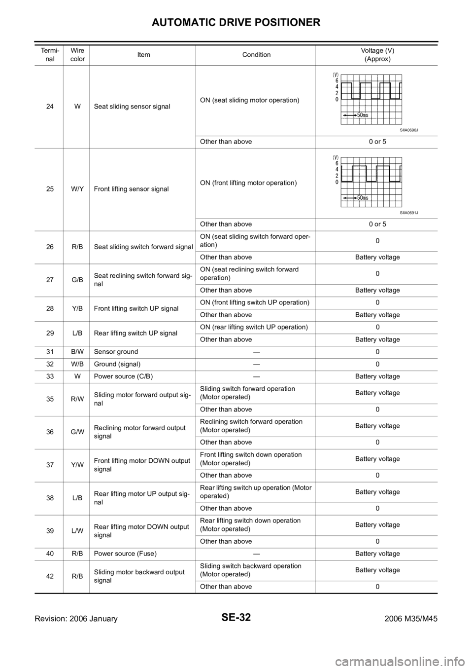
SE-32
AUTOMATIC DRIVE POSITIONER
Revision: 2006 January2006 M35/M45
24 W Seat sliding sensor signalON (seat sliding motor operation)
Other than above 0 or 5
25 W/Y Front lifting sensor signalON (front lifting motor operation)
Other than above 0 or 5
26 R/B Seat sliding switch forward signalON (seat sliding switch forward oper-
ation)0
Other than above Battery voltage
27 G/BSeat reclining switch forward sig-
nalON (seat reclining switch forward
operation)0
Other than above Battery voltage
28 Y/B Front lifting switch UP signalON (front lifting switch UP operation) 0
Other than above Battery voltage
29 L/B Rear lifting switch UP signalON (rear lifting switch UP operation) 0
Other than above Battery voltage
31 B/W Sensor ground — 0
32 W/B Ground (signal) — 0
33 W Power source (C/B) — Battery voltage
35 R/WSliding motor forward output sig-
nalSliding switch forward operation
(Motor operated)Battery voltage
Other than above 0
36 G/WReclining motor forward output
signalReclining switch forward operation
(Motor operated)Battery voltage
Other than above 0
37 Y/WFront lifting motor DOWN output
signalFront lifting switch down operation
(Motor operated)Battery voltage
Other than above 0
38 L/BRear lifting motor UP output sig-
nalRear lifting switch up operation (Motor
operated)Battery voltage
Other than above 0
39 L/WRear lifting motor DOWN output
signalRear lifting switch down operation
(Motor operated)Battery voltage
Other than above 0
40 R/B Power source (Fuse) — Battery voltage
42 R/BSliding motor backward output
signalSliding switch backward operation
(Motor operated)Battery voltage
Other than above 0 Te r m i -
nalWire
colorItem ConditionVoltage (V)
(Approx)
SIIA0690J
SIIA0691J