Page 5226 of 5621
AUTOMATIC DRIVE POSITIONER
SE-45
C
D
E
F
G
H
J
K
L
MA
B
SE
Revision: 2006 January2006 M35/M45
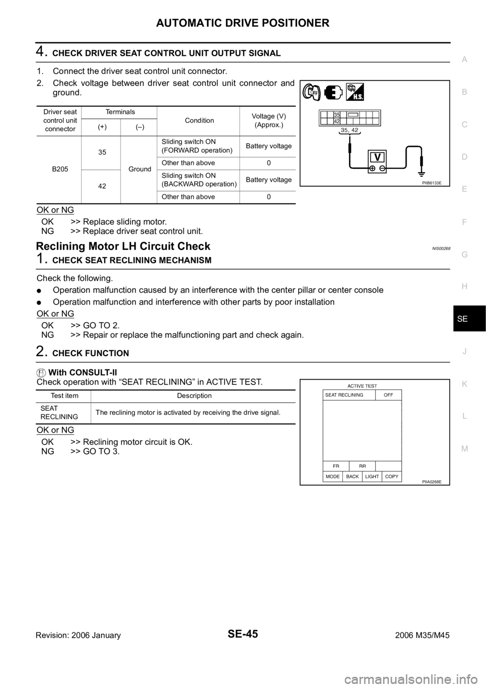
4. CHECK DRIVER SEAT CONTROL UNIT OUTPUT SIGNAL
1. Connect the driver seat control unit connector.
2. Check voltage between driver seat control unit connector and
ground.
OK or NG
OK >> Replace sliding motor.
NG >> Replace driver seat control unit.
Reclining Motor LH Circuit CheckNIS00268
1. CHECK SEAT RECLINING MECHANISM
Check the following.
Operation malfunction caused by an interference with the center pillar or center console
Operation malfunction and interference with other parts by poor installation
OK or NG
OK >> GO TO 2.
NG >> Repair or replace the malfunctioning part and check again.
2. CHECK FUNCTION
With CONSULT-II
Check operation with “SEAT RECLINING” in ACTIVE TEST.
OK or NG
OK >> Reclining motor circuit is OK.
NG >> GO TO 3.
Driver seat
control unit
connectorTerminals
ConditionVoltage (V)
(Approx.)
(+) (–)
B20535
GroundSliding switch ON
(FORWARD operation)Battery voltage
Other than above 0
42Sliding switch ON
(BACKWARD operation)Battery voltage
Other than above 0
PIIB6133E
Test item Description
SEAT
RECLININGThe reclining motor is activated by receiving the drive signal.
PIIA0268E
Page 5227 of 5621
SE-46
AUTOMATIC DRIVE POSITIONER
Revision: 2006 January2006 M35/M45
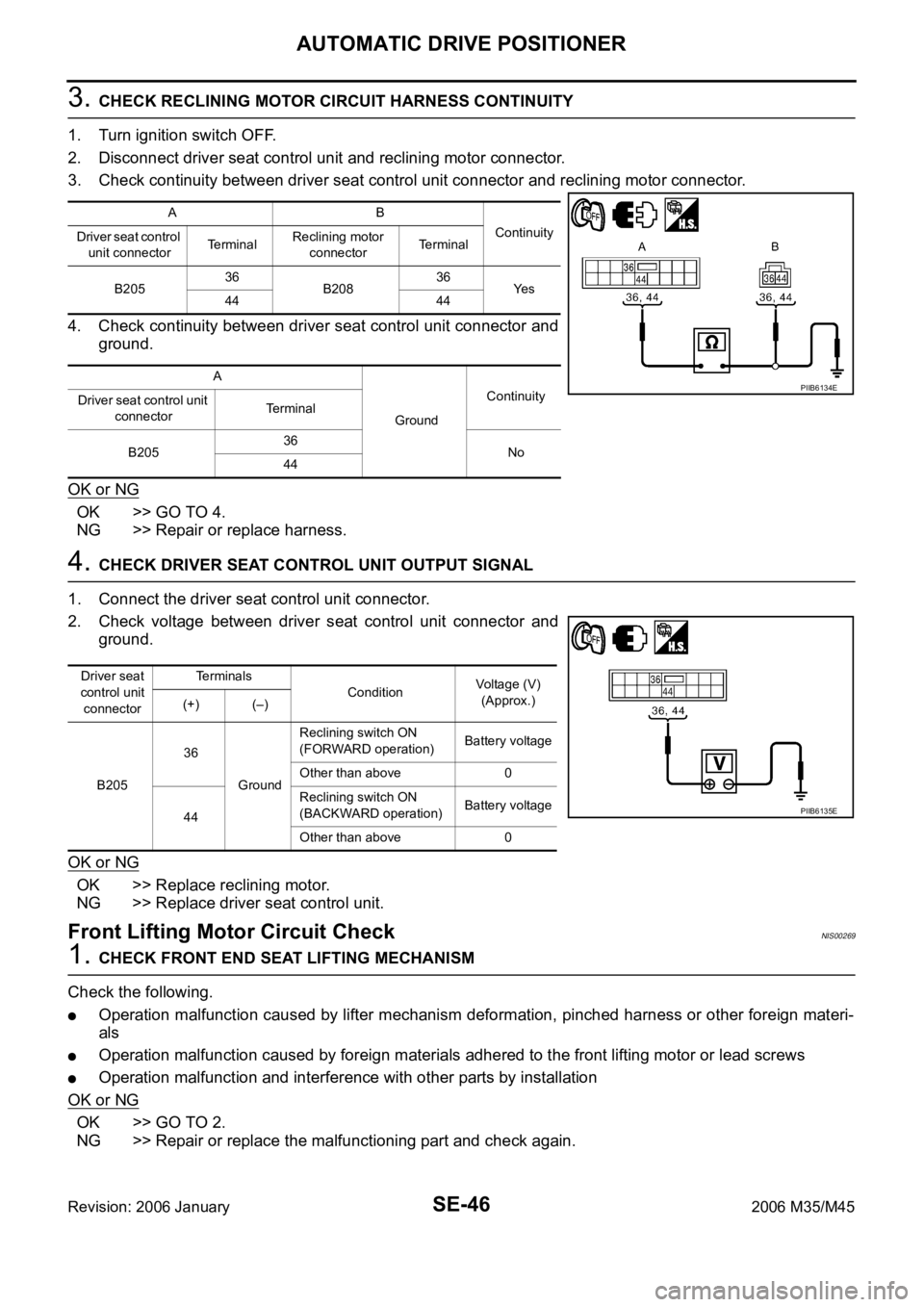
3. CHECK RECLINING MOTOR CIRCUIT HARNESS CONTINUITY
1. Turn ignition switch OFF.
2. Disconnect driver seat control unit and reclining motor connector.
3. Check continuity between driver seat control unit connector and reclining motor connector.
4. Check continuity between driver seat control unit connector and
ground.
OK or NG
OK >> GO TO 4.
NG >> Repair or replace harness.
4. CHECK DRIVER SEAT CONTROL UNIT OUTPUT SIGNAL
1. Connect the driver seat control unit connector.
2. Check voltage between driver seat control unit connector and
ground.
OK or NG
OK >> Replace reclining motor.
NG >> Replace driver seat control unit.
Front Lifting Motor Circuit CheckNIS00269
1. CHECK FRONT END SEAT LIFTING MECHANISM
Check the following.
Operation malfunction caused by lifter mechanism deformation, pinched harness or other foreign materi-
als
Operation malfunction caused by foreign materials adhered to the front lifting motor or lead screws
Operation malfunction and interference with other parts by installation
OK or NG
OK >> GO TO 2.
NG >> Repair or replace the malfunctioning part and check again.
AB
Continuity
Driver seat control
unit connectorTe r m i n a lReclining motor
connectorTerminal
B20536
B20836
Ye s
44 44
A
GroundContinuity
Driver seat control unit
connectorTerminal
B20536
No
44
PIIB6134E
Driver seat
control unit
connectorTerminals
ConditionVoltage (V)
(Approx.)
(+) (–)
B20536
GroundReclining switch ON
(FORWARD operation)Battery voltage
Other than above 0
44Reclining switch ON
(BACKWARD operation)Battery voltage
Other than above 0
PIIB6135E
Page 5228 of 5621
AUTOMATIC DRIVE POSITIONER
SE-47
C
D
E
F
G
H
J
K
L
MA
B
SE
Revision: 2006 January2006 M35/M45
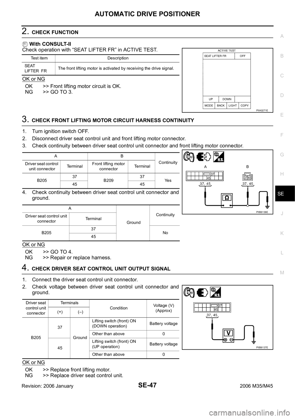
2. CHECK FUNCTION
With CONSULT-II
Check operation with “SEAT LIFTER FR” in ACTIVE TEST.
OK or NG
OK >> Front lifting motor circuit is OK.
NG >> GO TO 3.
3. CHECK FRONT LIFTING MOTOR CIRCUIT HARNESS CONTINUITY
1. Turn ignition switch OFF.
2. Disconnect driver seat control unit and front lifting motor connector.
3. Check continuity between driver seat control unit connector and front lifting motor connector.
4. Check continuity between driver seat control unit connector and
ground.
OK or NG
OK >> GO TO 4.
NG >> Repair or replace harness.
4. CHECK DRIVER SEAT CONTROL UNIT OUTPUT SIGNAL
1. Connect the driver seat control unit connector.
2. Check voltage between driver seat control unit connector and
ground.
OK or NG
OK >> Replace front lifting motor.
NG >> Replace driver seat control unit.
Test item Description
SEAT
LIFTER FRThe front lifting motor is activated by receiving the drive signal.
PIIA0271E
AB
Continuity
Driver seat control
unit connectorTerminalFront lifting motor
connectorTerminal
B20537
B20937
Ye s
45 45
A
GroundContinuity
Driver seat control unit
connectorTerminal
B20537
No
45
PIIB6136E
Driver seat
control unit
connectorTe r m i n a l s
ConditionVoltage (V)
(Approx)
(+) (–)
B20537
GroundLifting switch (front) ON
(DOWN operation)Battery voltage
Other than above 0
45Lifting switch (front) ON
(UP operation)Battery voltage
Other than above 0
PIIB6137E
Page 5229 of 5621
SE-48
AUTOMATIC DRIVE POSITIONER
Revision: 2006 January2006 M35/M45
Rear Lifting Motor Circuit CheckNIS0026A
1. CHECK REAR SEAT LIFTING MECHANISM
Check the following.
Operation malfunction caused by lifter mechanism deformation or pinched harness or other foreign mate-
rials
Operation malfunction caused by foreign materials adhered to the rear lifting motor or lead screws
Operation malfunction and interference with other parts by poor installation
OK or NG
OK >> GO TO 2.
NG >> Repair or replace the malfunctioning part and check again.
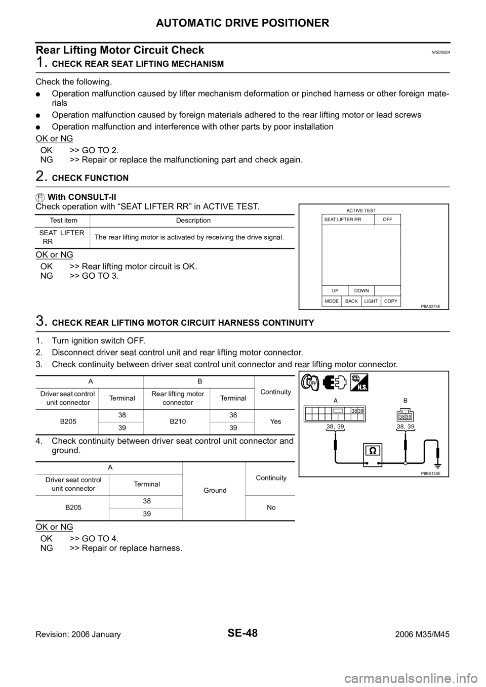
2. CHECK FUNCTION
With CONSULT-II
Check operation with “SEAT LIFTER RR” in ACTIVE TEST.
OK or NG
OK >> Rear lifting motor circuit is OK.
NG >> GO TO 3.
3. CHECK REAR LIFTING MOTOR CIRCUIT HARNESS CONTINUITY
1. Turn ignition switch OFF.
2. Disconnect driver seat control unit and rear lifting motor connector.
3. Check continuity between driver seat control unit connector and rear lifting motor connector.
4. Check continuity between driver seat control unit connector and
ground.
OK or NG
OK >> GO TO 4.
NG >> Repair or replace harness.
Test item Description
SEAT LIFTER
RRThe rear lifting motor is activated by receiving the drive signal.
PIIA0274E
AB
Continuity
Driver seat control
unit connectorTe r m i n a lRear lifting motor
connectorTerminal
B20538
B21038
Ye s
39 39
A
GroundContinuity
Driver seat control
unit connectorTerminal
B20538
No
39
PIIB6138E
Page 5230 of 5621

AUTOMATIC DRIVE POSITIONER
SE-49
C
D
E
F
G
H
J
K
L
MA
B
SE
Revision: 2006 January2006 M35/M45
4. CHECK DRIVER SEAT CONTROL UNIT OUTPUT SIGNAL
1. Connect the driver seat control unit connector.
2. Check voltage between driver seat control unit connector and ground.
OK or NG
OK >> Replace rear lifting motor.
NG >> Replace driver seat control unit.
Telescopic Motor Circuit CheckNIS0026B
1. CHECK STEERING WHEEL TELESCOPIC MECHANISM
Check following.
Operation malfunction caused by steering wheel telescopic mechanism deformation or pinched harness
or other foreign materials
Operation malfunction and interference with other parts by poor installation
OK or NG
OK >> GO TO 2.
NG >> Repair the malfunctioning part and check again.
2. CHECK FUNCTION
With CONSULT-II
Check operation with “TELESCO MOTOR” in ACTIVE TEST.
OK or NG
OK >> Steering telescopic motor circuit is OK.
NG >> GO TO 3.
Driver
seat con-
trol unit
connectorTe r m i n a l s
ConditionVoltage (V)
(Approx.)
(+) (–)
B20538
GroundLifting switch (rear) ON
(UP operation)Battery voltage
Other than above 0
39Lifting switch (rear) ON
(DOWN operation)Battery voltage
Other than above 0
PIIB6139E
Test item Description
TELESCO
MOTORThe telescopic motor is activated by receiving the drive signal.
PIIA0277E
Page 5231 of 5621
SE-50
AUTOMATIC DRIVE POSITIONER
Revision: 2006 January2006 M35/M45
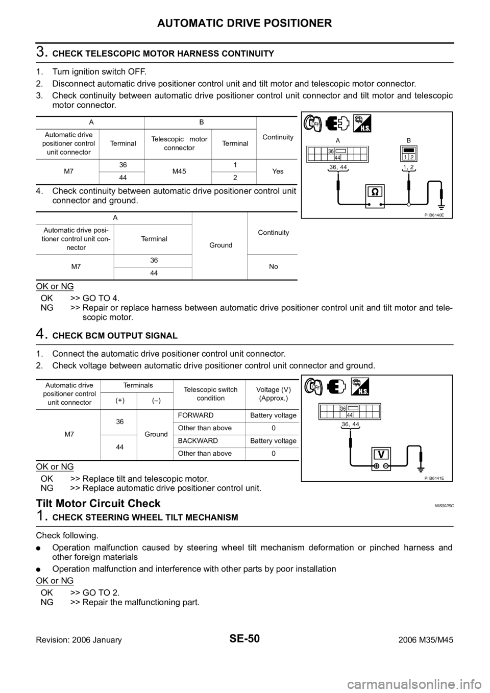
3. CHECK TELESCOPIC MOTOR HARNESS CONTINUITY
1. Turn ignition switch OFF.
2. Disconnect automatic drive positioner control unit and tilt motor and telescopic motor connector.
3. Check continuity between automatic drive positioner control unit connector and tilt motor and telescopic
motor connector.
4. Check continuity between automatic drive positioner control unit
connector and ground.
OK or NG
OK >> GO TO 4.
NG >> Repair or replace harness between automatic drive positioner control unit and tilt motor and tele-
scopic motor.
4. CHECK BCM OUTPUT SIGNAL
1. Connect the automatic drive positioner control unit connector.
2. Check voltage between automatic drive positioner control unit connector and ground.
OK or NG
OK >> Replace tilt and telescopic motor.
NG >> Replace automatic drive positioner control unit.
Tilt Motor Circuit CheckNIS0026C
1. CHECK STEERING WHEEL TILT MECHANISM
Check following.
Operation malfunction caused by steering wheel tilt mechanism deformation or pinched harness and
other foreign materials
Operation malfunction and interference with other parts by poor installation
OK or NG
OK >> GO TO 2.
NG >> Repair the malfunctioning part.
AB
Continuity Automatic drive
positioner control
unit connectorTe r m i n a lTelescopic motor
connectorTerminal
M736
M451
Ye s
44 2
A
GroundContinuity Automatic drive posi-
tioner control unit con-
nectorTerminal
M736
No
44
PIIB6140E
Automatic drive
positioner control
unit connectorTerminals
Telescopic switch
conditionVoltage (V)
(Approx.)
(+) (–)
M736
GroundFORWARD Battery voltage
Other than above 0
44BACKWARD Battery voltage
Other than above 0
PIIB6141E
Page 5232 of 5621
AUTOMATIC DRIVE POSITIONER
SE-51
C
D
E
F
G
H
J
K
L
MA
B
SE
Revision: 2006 January2006 M35/M45
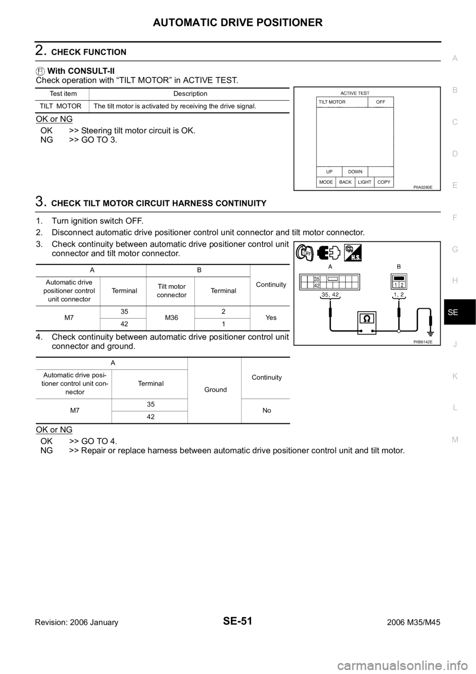
2. CHECK FUNCTION
With CONSULT-II
Check operation with “TILT MOTOR” in ACTIVE TEST.
OK or NG
OK >> Steering tilt motor circuit is OK.
NG >> GO TO 3.
3. CHECK TILT MOTOR CIRCUIT HARNESS CONTINUITY
1. Turn ignition switch OFF.
2. Disconnect automatic drive positioner control unit connector and tilt motor connector.
3. Check continuity between automatic drive positioner control unit
connector and tilt motor connector.
4. Check continuity between automatic drive positioner control unit
connector and ground.
OK or NG
OK >> GO TO 4.
NG >> Repair or replace harness between automatic drive positioner control unit and tilt motor.
Test item Description
TILT MOTOR The tilt motor is activated by receiving the drive signal.
PIIA0280E
AB
Continuity Automatic drive
positioner control
unit connectorTerminalTilt motor
connectorTerminal
M735
M362
Ye s
42 1
A
GroundContinuity Automatic drive posi-
tioner control unit con-
nectorTerminal
M735
No
42
PIIB6142E
Page 5233 of 5621
SE-52
AUTOMATIC DRIVE POSITIONER
Revision: 2006 January2006 M35/M45
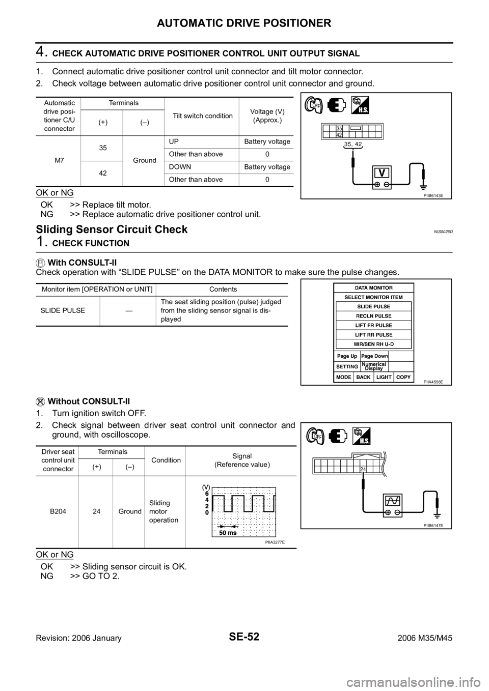
4. CHECK AUTOMATIC DRIVE POSITIONER CONTROL UNIT OUTPUT SIGNAL
1. Connect automatic drive positioner control unit connector and tilt motor connector.
2. Check voltage between automatic drive positioner control unit connector and ground.
OK or NG
OK >> Replace tilt motor.
NG >> Replace automatic drive positioner control unit.
Sliding Sensor Circuit CheckNIS0026D
1. CHECK FUNCTION
With CONSULT-II
Check operation with “SLIDE PULSE” on the DATA MONITOR to make sure the pulse changes.
Without CONSULT-II
1. Turn ignition switch OFF.
2. Check signal between driver seat control unit connector and
ground, with oscilloscope.
OK or NG
OK >> Sliding sensor circuit is OK.
NG >> GO TO 2.
Automatic
drive posi-
tioner C/U
connectorTerminals
Tilt switch conditionVoltage (V)
(Approx.)
(+) (–)
M735
GroundUP Battery voltage
Other than above 0
42DOWN Battery voltage
Other than above 0
PIIB6143E
Monitor item [OPERATION or UNIT] Contents
SLIDE PULSE —The seat sliding position (pulse) judged
from the sliding sensor signal is dis-
played
PIIA4558E
Driver seat
control unit
connectorTerminals
ConditionSignal
(Reference value)
(+) (–)
B204 24 GroundSliding
motor
operation
PIIB6147E
PIIA3277E