Page 5258 of 5621
AUTOMATIC DRIVE POSITIONER
SE-77
C
D
E
F
G
H
J
K
L
MA
B
SE
Revision: 2006 January2006 M35/M45
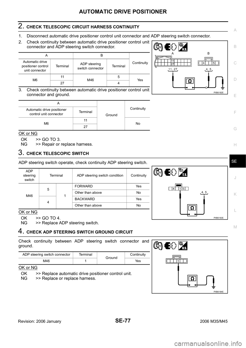
2. CHECK TELESCOPIC CIRCUIT HARNESS CONTINUITY
1. Disconnect automatic drive positioner control unit connector and ADP steering switch connector.
2. Check continuity between automatic drive positioner control unit
connector and ADP steering switch connector.
3. Check continuity between automatic drive positioner control unit
connector and ground.
OK or NG
OK >> GO TO 3.
NG >> Repair or replace harness.
3. CHECK TELESCOPIC SWITCH
ADP steering switch operate, check continuity ADP steering switch.
OK or NG
OK >> GO TO 4.
NG >> Replace ADP steering switch.
4. CHECK ADP STEERING SWITCH GROUND CIRCUIT
Check continuity between ADP steering switch connector and
ground.
OK or NG
OK >> Replace automatic drive positioner control unit.
NG >> Replace or replace harness.
AB
Continuity Automatic drive
positioner control
unit connectorTerminalADP steering
switch connectorTerminal
M611
M465
Ye s
27 4
A
GroundContinuity
Automatic drive positioner
control unit connectorTerminal
M611
No
27
PIIB6182E
ADP
steering
switchTerminal ADP steering switch condition Continuity
M465
1FORWARD Yes
Other than above No
4BACKWARD Yes
Other than above No
PIIB6183E
ADP steering switch connector Terminal
GroundContinuity
M46 1 Yes
PIIB6184E
Page 5259 of 5621
SE-78
AUTOMATIC DRIVE POSITIONER
Revision: 2006 January2006 M35/M45
Tilt Switch Circuit CheckNIS0026R
1. CHECK FUNCTION
With CONSULT-II
With “TILT SW-UP,TILT SW-DOWN” on the DATA MONITOR, operate the ADP steering switch to check ON/
OFF operation.
Without CONSULT-II
1. Turn ignition switch OFF.
2. Check voltage between automatic drive positioner control unit connector and ground.
OK or NG
OK >> Tilt switch circuit is OK.
NG >> GO TO 2.
Monitor item
[OPERATION or UNIT]Contents
TILT SW-UP “ON/OFF” (ON/OFF) status judged from the tilt switch
(UP) signal is displayed.
TILT SW-DOWN “ON/OFF”(ON/OFF) status judged from the tilt switch
(DOWN) signal is displayed.
PIIA0315E
Auto-
matic
drive posi-
tioner
control
unit con-
nectorTe r m i n a l s
Tilt switch conditionVoltage (V)
(Approx.)
(+) (–)
M61
GroundUP 0
Other than above 5
17DOWN 0
Other than above 5
PIIB6185E
Page 5260 of 5621
AUTOMATIC DRIVE POSITIONER
SE-79
C
D
E
F
G
H
J
K
L
MA
B
SE
Revision: 2006 January2006 M35/M45
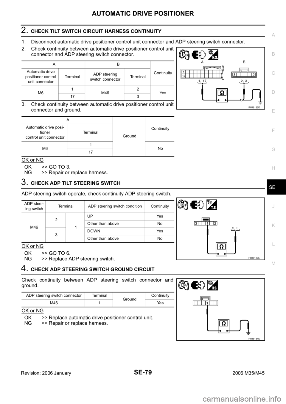
2. CHECK TILT SWITCH CIRCUIT HARNESS CONTINUITY
1. Disconnect automatic drive positioner control unit connector and ADP steering switch connector.
2. Check continuity between automatic drive positioner control unit
connector and ADP steering switch connector.
3. Check continuity between automatic drive positioner control unit
connector and ground.
OK or NG
OK >> GO TO 3.
NG >> Repair or replace harness.
3. CHECK ADP TILT STEERING SWITCH
ADP steering switch operate, check continuity ADP steering switch.
OK or NG
OK >> GO TO 6.
NG >> Replace ADP steering switch.
4. CHECK ADP STEERING SWITCH GROUND CIRCUIT
Check continuity between ADP steering switch connector and
ground.
OK or NG
OK >> Replace automatic drive positioner control unit.
NG >> Repair or replace harness.
AB
Continuity Automatic drive
positioner control
unit connectorTerminalADP steering
switch connectorTerminal
M61
M462
Ye s
17 3
A
GroundContinuity Automatic drive posi-
tioner
control unit connectorTerminal
M61
No
17
PIIB6186E
ADP steer-
ing switchTerminal ADP steering switch condition Continuity
M462
1UP Yes
Other than above No
3DOWN Yes
Other than above No
PIIB6187E
ADP steering switch connector Terminal
GroundContinuity
M46 1 Yes
PIIB6184E
Page 5261 of 5621
SE-80
AUTOMATIC DRIVE POSITIONER
Revision: 2006 January2006 M35/M45
Seat Memory and Set Switch Circuit CheckNIS0026S
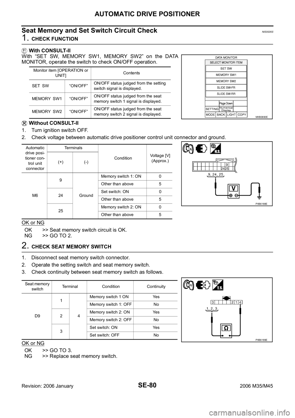
1. CHECK FUNCTION
With CONSULT-II
With “SET SW, MEMORY SW1, MEMORY SW2” on the DATA
MONITOR, operate the switch to check ON/OFF operation.
Without CONSULT-II
1. Turn ignition switch OFF.
2. Check voltage between automatic drive positioner control unit connector and ground.
OK or NG
OK >> Seat memory switch circuit is OK.
NG >> GO TO 2.
2. CHECK SEAT MEMORY SWITCH
1. Disconnect seat memory switch connector.
2. Operate the setting switch and seat memory switch.
3. Check continuity between seat memory switch as follows.
OK or NG
OK >> GO TO 3.
NG >> Replace seat memory switch.
Monitor item [OPERATION or
UNIT]Contents
SET SW “ON/OFF”ON/OFF status judged from the setting
switch signal is displayed.
MEMORY SW1 “ON/OFF”ON/OFF status judged from the seat
memory switch 1 signal is displayed.
MEMORY SW2 “ON/OFF”ON/OFF status judged from the seat
memory switch 2 signal is displayed.
Automatic
drive posi-
tioner con-
trol unit
connectorTerminals
ConditionVoltage [V]
(Approx.)
(+) (-)
M69
GroundMemory switch 1: ON 0
Other than above 5
24Set switch: ON 0
Other than above 5
25Memory switch 2: ON 0
Other than above 5
MIIB0690E
PIIB6188E
Seat memory
switchTerminal Condition Continuity
D91
4Memory switch 1 ON Yes
Memory switch 1: OFF No
2Memory switch 2: ON Yes
Memory switch 2: OFF No
3Set switch: ON Yes
Set switch: OFF No
PIIB6189E
Page 5262 of 5621
AUTOMATIC DRIVE POSITIONER
SE-81
C
D
E
F
G
H
J
K
L
MA
B
SE
Revision: 2006 January2006 M35/M45
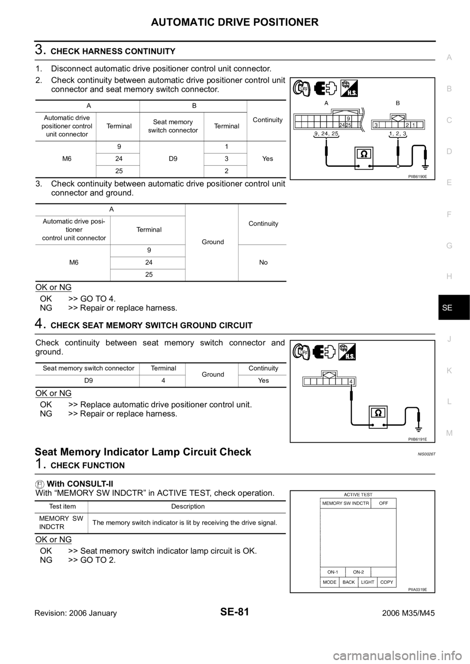
3. CHECK HARNESS CONTINUITY
1. Disconnect automatic drive positioner control unit connector.
2. Check continuity between automatic drive positioner control unit
connector and seat memory switch connector.
3. Check continuity between automatic drive positioner control unit
connector and ground.
OK or NG
OK >> GO TO 4.
NG >> Repair or replace harness.
4. CHECK SEAT MEMORY SWITCH GROUND CIRCUIT
Check continuity between seat memory switch connector and
ground.
OK or NG
OK >> Replace automatic drive positioner control unit.
NG >> Repair or replace harness.
Seat Memory Indicator Lamp Circuit CheckNIS0026T
1. CHECK FUNCTION
With CONSULT-II
With “MEMORY SW INDCTR” in ACTIVE TEST, check operation.
OK or NG
OK >> Seat memory switch indicator lamp circuit is OK.
NG >> GO TO 2.
AB
Continuity Automatic drive
positioner control
unit connectorTerminalSeat memory
switch connectorTerminal
M69
D91
Ye s 24 3
25 2
A
GroundContinuity Automatic drive posi-
tioner
control unit connectorTerminal
M69
No 24
25
PIIB6190E
Seat memory switch connector Terminal
GroundContinuity
D9 4 Yes
PIIB6191E
Test item Description
MEMORY SW
INDCTRThe memory switch indicator is lit by receiving the drive signal.
PIIA0319E
Page 5263 of 5621
SE-82
AUTOMATIC DRIVE POSITIONER
Revision: 2006 January2006 M35/M45
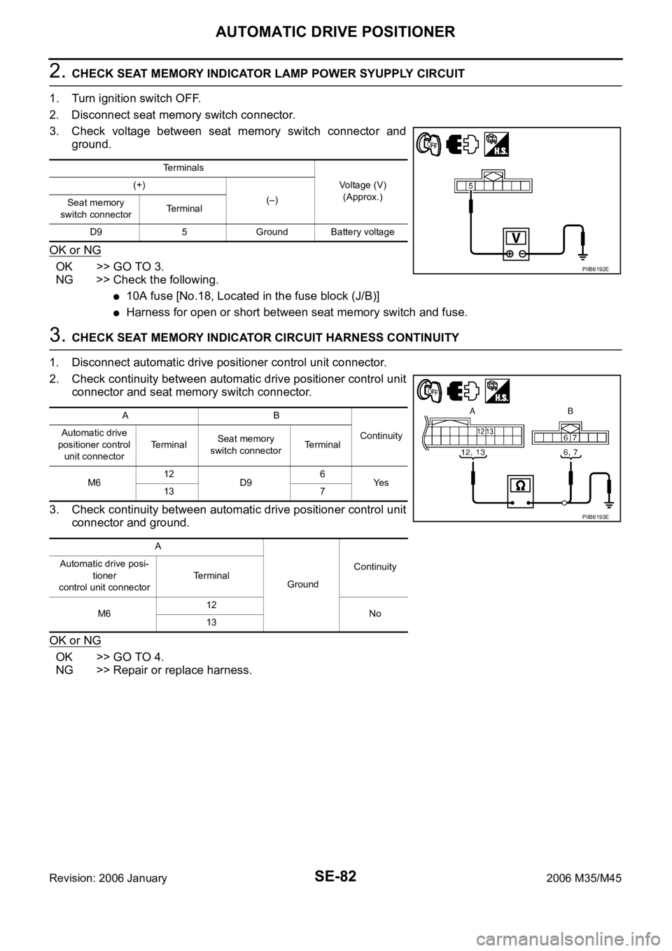
2. CHECK SEAT MEMORY INDICATOR LAMP POWER SYUPPLY CIRCUIT
1. Turn ignition switch OFF.
2. Disconnect seat memory switch connector.
3. Check voltage between seat memory switch connector and
ground.
OK or NG
OK >> GO TO 3.
NG >> Check the following.
10A fuse [No.18, Located in the fuse block (J/B)]
Harness for open or short between seat memory switch and fuse.
3. CHECK SEAT MEMORY INDICATOR CIRCUIT HARNESS CONTINUITY
1. Disconnect automatic drive positioner control unit connector.
2. Check continuity between automatic drive positioner control unit
connector and seat memory switch connector.
3. Check continuity between automatic drive positioner control unit
connector and ground.
OK or NG
OK >> GO TO 4.
NG >> Repair or replace harness.
Terminals
Voltage (V)
(Approx.) (+)
(–)
Seat memory
switch connectorTerminal
D9 5 Ground Battery voltage
PIIB6192E
AB
Continuity Automatic drive
positioner control
unit connectorTe r m i n a lSeat memory
switch connectorTerminal
M612
D96
Ye s
13 7
A
GroundContinuity Automatic drive posi-
tioner
control unit connectorTerminal
M612
No
13
PIIB6193E
Page 5264 of 5621
AUTOMATIC DRIVE POSITIONER
SE-83
C
D
E
F
G
H
J
K
L
MA
B
SE
Revision: 2006 January2006 M35/M45
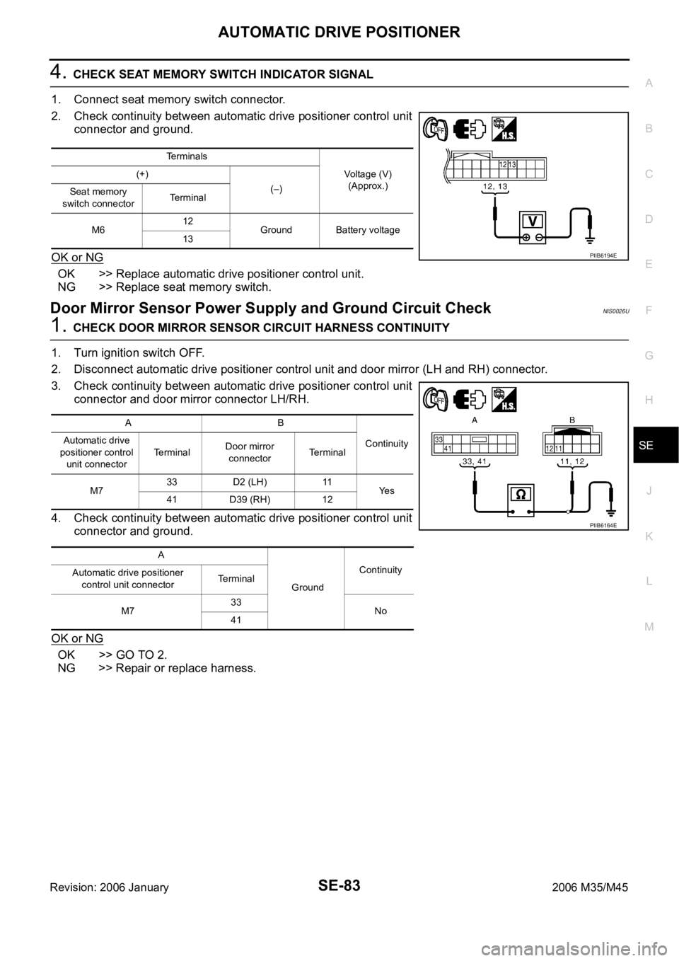
4. CHECK SEAT MEMORY SWITCH INDICATOR SIGNAL
1. Connect seat memory switch connector.
2. Check continuity between automatic drive positioner control unit
connector and ground.
OK or NG
OK >> Replace automatic drive positioner control unit.
NG >> Replace seat memory switch.
Door Mirror Sensor Power Supply and Ground Circuit CheckNIS0026U
1. CHECK DOOR MIRROR SENSOR CIRCUIT HARNESS CONTINUITY
1. Turn ignition switch OFF.
2. Disconnect automatic drive positioner control unit and door mirror (LH and RH) connector.
3. Check continuity between automatic drive positioner control unit
connector and door mirror connector LH/RH.
4. Check continuity between automatic drive positioner control unit
connector and ground.
OK or NG
OK >> GO TO 2.
NG >> Repair or replace harness.
Terminals
Voltage (V)
(Approx.) (+)
(–)
Seat memory
switch connectorTerminal
M612
Ground Battery voltage
13
PIIB6194E
AB
Continuity Automatic drive
positioner control
unit connectorTerminalDoor mirror
connectorTerminal
M733 D2 (LH) 11
Ye s
41 D39 (RH) 12
A
GroundContinuity
Automatic drive positioner
control unit connectorTerminal
M733
No
41
PIIB6164E
Page 5265 of 5621
SE-84
AUTOMATIC DRIVE POSITIONER
Revision: 2006 January2006 M35/M45
2. CHECK MIRROR SENSOR POWER SUPPLY
1. Connect automatic drive positioner control unit connector.
2. Turn ignition switch to ACC.
3. Check voltage between automatic drive positioner control unit
connector and ground.
OK or NG
OK >> GO TO 3.
NG >> Replace automatic drive positioner control unit.
3. CHECK MIRROR SENSOR GROUND CIRCUIT
1. Turn ignition switch OFF.
2. Check continuity between automatic drive positioner control unit
connector and ground.
OK or NG
OK >> Door mirror power supply and ground circuit are OK.
NG >> Replace automatic drive positioner control unit.
Terminals
Voltage (V)
(Approx.) (+)
(–) Automatic drive
positioner control
unit connectorTerminal
M6 33 Ground 5
PIIB6196E
Automatic drive positioner
control unit connectorTerminal
GroundContinuity
M6 41 Yes
PIIB6197E