Page 5277 of 5621

SE-96
POWER SEAT(REAR)
Revision: 2006 January2006 M35/M45
Then ground is supplied
through rear seat sliding motor terminals 5,
through body grounds B5, B40, B131.
When power and ground are supplied, rear power seat slide moves forward.
When rear power seat switch is backward, ground is supplied
to rear seat control unit terminal 15,
through rear power seat switch terminal 1,
through rear power seat switch terminal 3,
through body grounds B5, B40, B131.
When rear seat control unit receives power seat switch backward signal, power is supplied
to rear seat control unit terminal 7,
through rear seat sliding motor terminal 4.
Then ground is supplied
through rear seat sliding motor terminals 5,
through body grounds B5, B40, B131.
When power and ground are supplied, rear power seat slide moves backward.
REAR SEAT RETREAT FUNCTION
When rear door open, ground is supplied
to rear seat control unit terminal 16,
through rear door switch terminal 2,
When rear seat control unit receives automatic return cancel switch ON and rear door switch open signal,
power is supplied
through rear seat control unit terminal 7,
to rear seat sliding motor terminal 4.
Then ground is supplied
through rear seat sliding motor terminals 5,
through body grounds B5, B40, B131.
When power and ground are supplied, rear power seat slide moves backward.
When rear seat sliding motor is operated, ground is supplied
to rear seat control unit terminal 12,
through rear seat sliding motor terminal 1,
through rear seat sliding motor terminal 2,
through rear seat control unit terminal 19,
through rear seat control unit terminals 13,
through body grounds B5, B40, B131.
Then rear seat control unit receives rear power seat sliding sensor signal.
The rear power seat control unit controls the seat position of the system operation with the signal.
Page 5283 of 5621
SE-102
POWER SEAT(REAR)
Revision: 2006 January2006 M35/M45
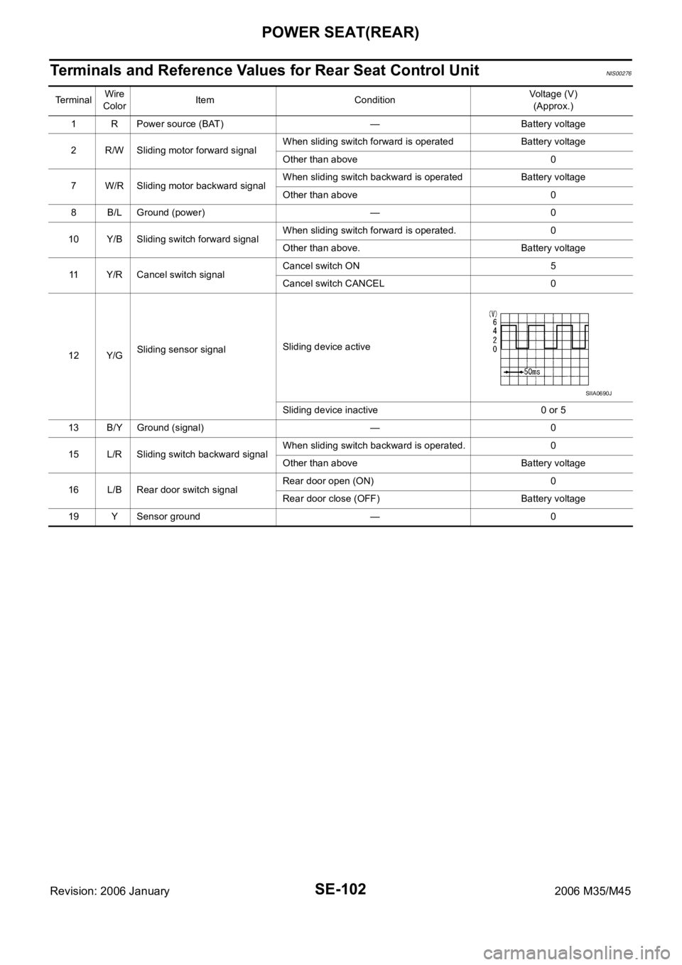
Terminals and Reference Values for Rear Seat Control Unit NIS00276
TerminalWire
ColorItem ConditionVoltage (V)
(Approx.)
1 R Power source (BAT) — Battery voltage
2 R/W Sliding motor forward signalWhen sliding switch forward is operated Battery voltage
Other than above 0
7 W/R Sliding motor backward signalWhen sliding switch backward is operated Battery voltage
Other than above 0
8 B/L Ground (power) — 0
10 Y/B Sliding switch forward signalWhen sliding switch forward is operated. 0
Other than above. Battery voltage
11 Y/R Cancel switch signalCancel switch ON 5
Cancel switch CANCEL 0
12 Y/GSliding sensor signalSliding device active
Sliding device inactive 0 or 5
13 B/Y Ground (signal) — 0
15 L/R Sliding switch backward signalWhen sliding switch backward is operated. 0
Other than above Battery voltage
16 L/B Rear door switch signalRear door open (ON) 0
Rear door close (OFF) Battery voltage
19 Y Sensor ground — 0
SIIA0690J
Page 5284 of 5621
POWER SEAT(REAR)
SE-103
C
D
E
F
G
H
J
K
L
MA
B
SE
Revision: 2006 January2006 M35/M45
Work FlowNIS00277
1. Check the symptom and customer's requests.
2. Understand the outline of system. Refer to SE-95, "
System Description" .
3. According to the trouble diagnosis chart, repair or replace the cause of the malfunction. Refer to SE-103,
"Trouble Diagnoses Symptom Chart" .
4. Does rear power seat operate normally? YES: GO TO 5, NO: GO TO 4.
5. INSPECTION END.
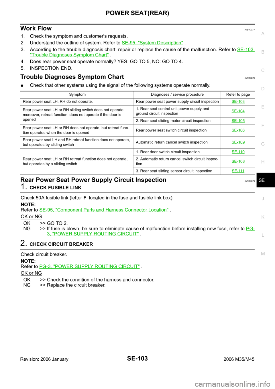
Trouble Diagnoses Symptom ChartNIS00278
Check that other systems using the signal of the following systems operate normally.
Rear Power Seat Power Supply Circuit InspectionNIS00279
1. CHECK FUSIBLE LINK
Check 50A fusible link (letter F located in the fuse and fusible link box).
NOTE:
Refer to SE-95, "
Component Parts and Harness Connector Location" .
OK or NG
OK >> GO TO 2.
NG >> If fuse is blown, be sure to eliminate cause of malfunction before installing new fuse, refer to PG-
3, "POWER SUPPLY ROUTING CIRCUIT" .
2. CHECK CIRCUIT BREAKER
Check circuit breaker.
NOTE:
Refer to PG-3, "
POWER SUPPLY ROUTING CIRCUIT" .
OK or NG
OK >> Check the condition of the harness and connector.
NG >> Replace the circuit breaker.
Symptom Diagnoses / service procedure Refer to page
Rear power seat LH, RH do not operate. Rear power seat power supply circuit inspectionSE-103
Rear power seat LH or RH sliding switch does not operate
moreover, retreat function does not operate if the door is
opened1. Rear seat control unit power supply and
ground circuit inspectionSE-104
2. Rear seat sliding motor circuit inspectionSE-105
Rear power seat LH or RH does not operate, but retreat func-
tion operates when the door is openedRear power seat switch circuit inspectionSE-106
Rear power seat LH and RH retreat function does not operate,
but operates by sliding switchAutomatic return cancel switch inspectionSE-109
Rear power seat LH or RH retreat function does not operate,
but operates by a sliding switch1. Rear door switch circuit inspectionSE-1102. Automatic return cancel switch circuit inspec-
tionSE-108
3. Rear seat sliding sensor circuit inspectionSE-111
Page 5285 of 5621
SE-104
POWER SEAT(REAR)
Revision: 2006 January2006 M35/M45
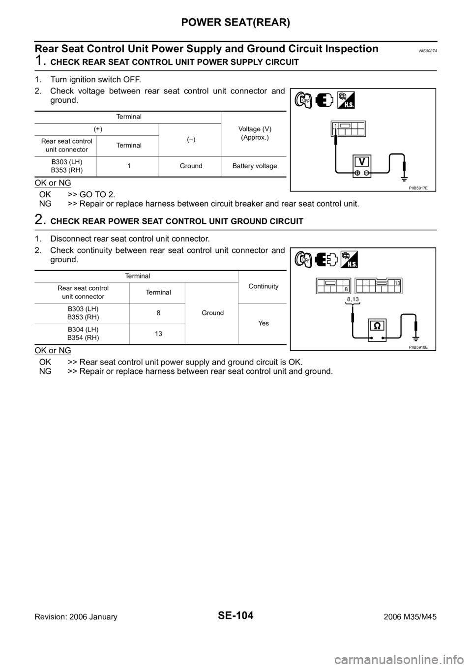
Rear Seat Control Unit Power Supply and Ground Circuit InspectionNIS0027A
1. CHECK REAR SEAT CONTROL UNIT POWER SUPPLY CIRCUIT
1. Turn ignition switch OFF.
2. Check voltage between rear seat control unit connector and
ground.
OK or NG
OK >> GO TO 2.
NG >> Repair or replace harness between circuit breaker and rear seat control unit.
2. CHECK REAR POWER SEAT CONTROL UNIT GROUND CIRCUIT
1. Disconnect rear seat control unit connector.
2. Check continuity between rear seat control unit connector and
ground.
OK or NG
OK >> Rear seat control unit power supply and ground circuit is OK.
NG >> Repair or replace harness between rear seat control unit and ground.
Terminal
Voltage (V)
(Approx.) (+)
(–)
Rear seat control
unit connectorTerminal
B303 (LH)
B353 (RH)1 Ground Battery voltage
PIIB5917E
Te r m i n a l
Continuity
Rear seat control
unit connectorTerminal
Ground B303 (LH)
B353 (RH)8
Ye s
B304 (LH)
B354 (RH)13
PIIB5918E
Page 5286 of 5621
POWER SEAT(REAR)
SE-105
C
D
E
F
G
H
J
K
L
MA
B
SE
Revision: 2006 January2006 M35/M45
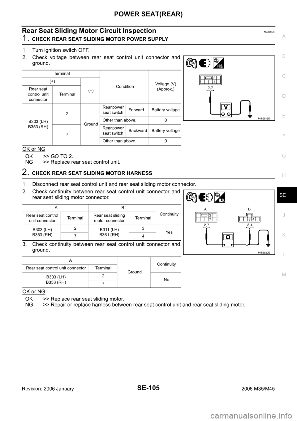
Rear Seat Sliding Motor Circuit InspectionNIS0027B
1. CHECK REAR SEAT SLIDING MOTOR POWER SUPPLY
1. Turn ignition switch OFF.
2. Check voltage between rear seat control unit connector and
ground.
OK or NG
OK >> GO TO 2.
NG >> Replace rear seat control unit.
2. CHECK REAR SEAT SLIDING MOTOR HARNESS
1. Disconnect rear seat control unit and rear seat sliding motor connector.
2. Check continuity between rear seat control unit connector and
rear seat sliding motor connector.
3. Check continuity between rear seat control unit connector and
ground.
OK or NG
OK >> Replace rear seat sliding motor.
NG >> Repair or replace harness between rear seat control unit and rear seat sliding motor.
Terminal
ConditionVoltage (V)
(Approx.) (+)
(–) Rear seat
control unit
connectorTerminal
B303 (LH)
B353 (RH)2
GroundRear power
seat switch Forward Battery voltage
Other than above. 0
7Rear power
seat switch Backward Battery voltage
Other than above. 0
PIIB5919E
AB
Continuity
Rear seat control
unit connectorTerminalRear seat sliding
motor connectorTerminal
B303 (LH)
B353 (RH)2
B311 (LH)
B361 (RH)3
Ye s
74
A
GroundContinuity
Rear seat control unit connector Terminal
B303 (LH)
B353 (RH)2
No
7
PIIB5920E
Page 5287 of 5621
SE-106
POWER SEAT(REAR)
Revision: 2006 January2006 M35/M45
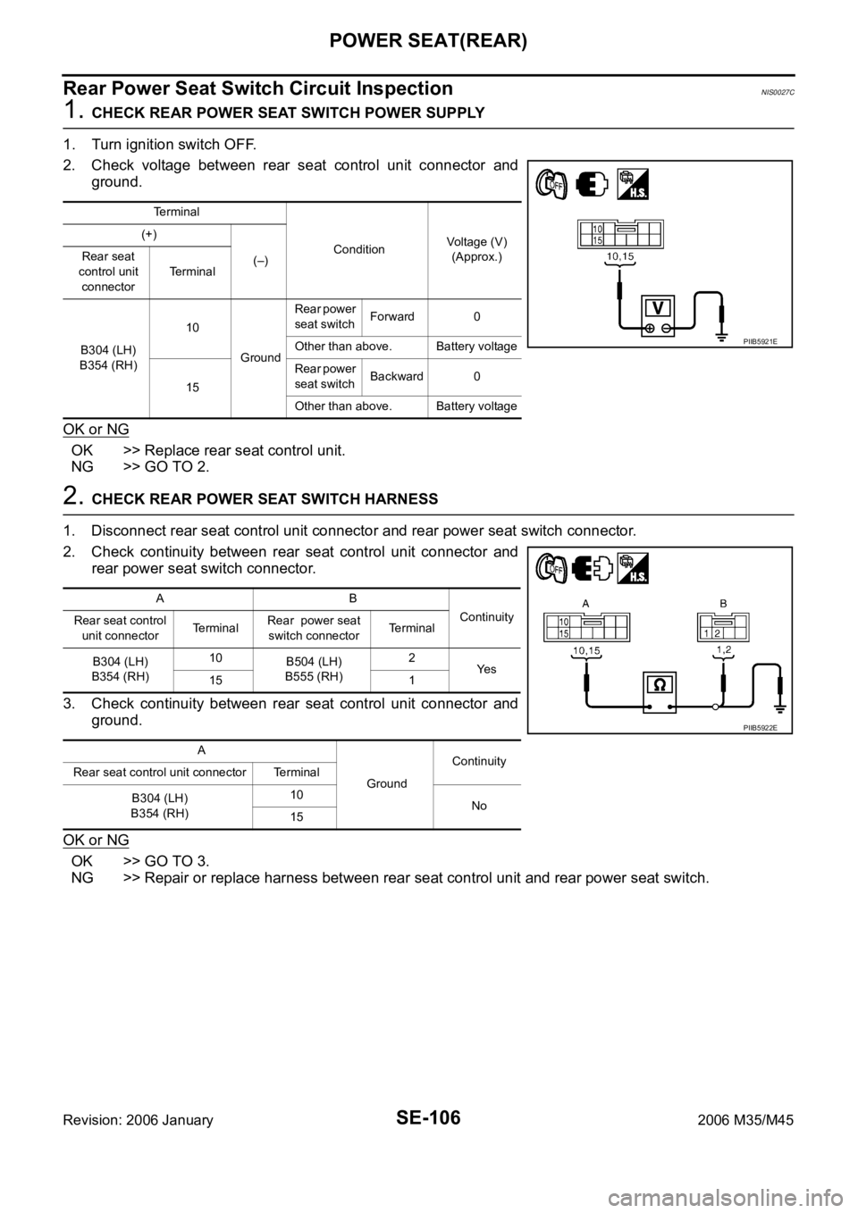
Rear Power Seat Switch Circuit InspectionNIS0027C
1. CHECK REAR POWER SEAT SWITCH POWER SUPPLY
1. Turn ignition switch OFF.
2. Check voltage between rear seat control unit connector and
ground.
OK or NG
OK >> Replace rear seat control unit.
NG >> GO TO 2.
2. CHECK REAR POWER SEAT SWITCH HARNESS
1. Disconnect rear seat control unit connector and rear power seat switch connector.
2. Check continuity between rear seat control unit connector and
rear power seat switch connector.
3. Check continuity between rear seat control unit connector and
ground.
OK or NG
OK >> GO TO 3.
NG >> Repair or replace harness between rear seat control unit and rear power seat switch.
Terminal
ConditionVoltage (V)
(Approx.) (+)
(–) Rear seat
control unit
connectorTerminal
B304 (LH)
B354 (RH)10
GroundRear power
seat switch Forward 0
Other than above. Battery voltage
15Rear power
seat switch Backward 0
Other than above. Battery voltage
PIIB5921E
AB
Continuity
Rear seat control
unit connectorTe r m i n a lRear power seat
switch connectorTerminal
B304 (LH)
B354 (RH)10
B504 (LH)
B555 (RH)2
Ye s
15 1
A
GroundContinuity
Rear seat control unit connector Terminal
B304 (LH)
B354 (RH)10
No
15
PIIB5922E
Page 5288 of 5621
POWER SEAT(REAR)
SE-107
C
D
E
F
G
H
J
K
L
MA
B
SE
Revision: 2006 January2006 M35/M45
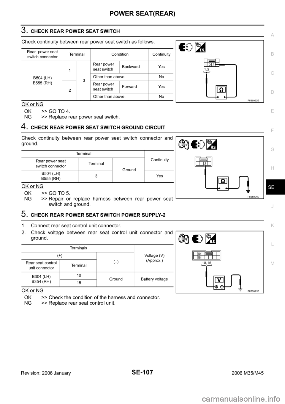
3. CHECK REAR POWER SEAT SWITCH
Check continuity between rear power seat switch as follows.
OK or NG
OK >> GO TO 4.
NG >> Replace rear power seat switch.
4. CHECK REAR POWER SEAT SWITCH GROUND CIRCUIT
Check continuity between rear power seat switch connector and
ground.
OK or NG
OK >> GO TO 5.
NG >> Repair or replace harness between rear power seat
switch and ground.
5. CHECK REAR POWER SEAT SWITCH POWER SUPPLY-2
1. Connect rear seat control unit connector.
2. Check voltage between rear seat control unit connector and
ground.
OK or NG
OK >> Check the condition of the harness and connector.
NG >> Replace rear seat control unit.
Rear power seat
switch connectorTerminal Condition Continuity
B504 (LH)
B555 (RH)1
3Rear power
seat switch Backward Yes
Other than above. No
2Rear power
seat switch Forward Yes
Other than above. No
PIIB5923E
Terminal
Continuity
Rear power seat
switch connectorTerminal
Ground
B504 (LH)
B555 (RH)3Yes
PIIB5924E
Terminals
Voltage (V)
(Approx.) (+)
(–)
Rear seat control
unit connectorTerminal
B304 (LH)
B354 (RH)10
Ground Battery voltage
15
PIIB5921E
Page 5289 of 5621
SE-108
POWER SEAT(REAR)
Revision: 2006 January2006 M35/M45
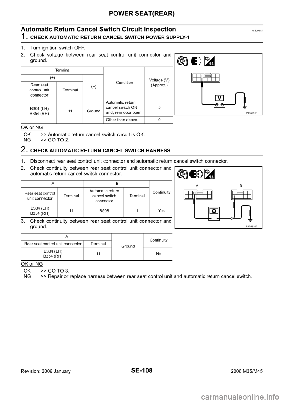
Automatic Return Cancel Switch Circuit InspectionNIS0027D
1. CHECK AUTOMATIC RETURN CANCEL SWITCH POWER SUPPLY-1
1. Turn ignition switch OFF.
2. Check voltage between rear seat control unit connector and
ground.
OK or NG
OK >> Automatic return cancel switch circuit is OK.
NG >> GO TO 2.
2. CHECK AUTOMATIC RETURN CANCEL SWITCH HARNESS
1. Disconnect rear seat control unit connector and automatic return cancel switch connector.
2. Check continuity between rear seat control unit connector and
automatic return cancel switch connector.
3. Check continuity between rear seat control unit connector and
ground.
OK or NG
OK >> GO TO 3.
NG >> Repair or replace harness between rear seat control unit and automatic return cancel switch.
Terminal
ConditionVoltage (V)
(Approx.) (+)
(–) Rear seat
control unit
connectorTerminal
B304 (LH)
B354 (RH)11 GroundAutomatic return
cancel switch ON
and, rear door open5
Other than above. 0
PIIB5925E
AB
Continuity
Rear seat control
unit connectorTe r m i n a lAutomatic return
cancel switch
connectorTerminal
B304 (LH)
B354 (RH)11 B508 1 Yes
A
GroundContinuity
Rear seat control unit connector Terminal
B304 (LH)
B354 (RH)11 N o
PIIB5926E