CLIMATE CONTROLLED SEAT
SE-141
C
D
E
F
G
H
J
K
L
MA
B
SE
Revision: 2006 January2006 M35/M45
2. CHECK CLIMATE CONTROLLED SEAT BLOWER MOTOR POWER SUPPLY CIRCUIT
1. Connect climate controlled seat control unit connector and blower motor connector.
2. Turn ignition switch ON.
3. Check voltage between climate controlled seat control unit con-
nector and ground.
OK or NG
OK >> GO TO 3.
NG >> Replace climate controlled seat control unit.
3. CHECK CLIMATE CONTROLLED SEAT BLOWER MOTOR SPEED CONTROL SIGNAL CIRCUIT
Check voltage between climate controlled seat control unit connec-
tor and ground.
OK or NG
OK >> GO TO 4.
NG >> Replace climate controlled seat control unit.
Terminal
ConditionVoltage (V)
(Approx.) (+)
(–) Climate
controlled
seat control unit
connectorTerminal
B283
(driver side)
B293
(passenger
side)14 GroundClimate
controlled
seat switchHEAT or
COOL5.5 -
Battery voltage
Other than above. 0
PIIB6090E
Terminal
ConditionVoltage (V)
(Approx.) (+)
(–) Climate
controlled
seat control
unit connectorTerminal
B283
(driver side)
B293
(passenger
side)17 GroundClimate
controlled
seat switchHEAT or
COOL4.5 - 8.0
Other than above. 0
PIIB6091E
SE-142
CLIMATE CONTROLLED SEAT
Revision: 2006 January2006 M35/M45
4. CHECK CLIMATE CONTROLLED SEAT BLOWER MOTOR TACHOMETER SIGNAL CIRCUIT
Check voltage between climate controlled seat control unit connec-
tor and ground.
OK or NG
OK >> Climate controlled seat blower motor circuit is OK.
NG >> Replace climate controlled seat blower motor.
Climate Controlled Seat Control Unit InspectionNIS0027Z
1. CHECK THE CLIMATE CONTROLLED SEAT CONTROL UNIT
Does the heater operate normally when the driver side or passenger side climate controlled seat control unit is
exchanged?
YES or NO
YES >> Climate controlled seat control unit is OK.
NO >> Replace climate controlled seat control unit.
Terminal
ConditionVoltage (V)
(Approx.) (+)
(–) Climate
controlled
seat control
unit connectorTerminal
B283
(driver side)
B293
(passenger
side)18 GroundClimate
controlled
seat switchHEAT or
COOL4.5 - 8.0
Other than above. 0
PIIB6092E
SE-144
HEATED SEAT
Revision: 2006 January2006 M35/M45
When rear heated seat switch (LH, RH) is LOW position, ground is suppled
to rear seat control unit terminal 18,
through rear heated seat switch terminal 2,
through rear heated seat switch terminal 3,
through body grounds B5, B40 and B131
Then rear seat control unit recognizes that rear heated seat switch is LOW position.
When rear heated seat switch is LOW position, power is supplied
through rear seat control unit terminal 6,
through rear seat cushion heater terminal 2,
through rear seat cushion heater terminal 3,
to rear seatback heater terminal 1.
Then ground is suppled
to rear seatback heater terminal 2.
through body grounds B5, B40 and B131.
With power and ground supplied, rear heated seat is operated.
When rear heated seat switch is in LOW position, ground is supplied
to rear heated seat switch terminal 5,
through rear seat control unit terminal 14,
through rear seat control unit terminal 13,
through body grounds B5, B40 and B131.
With power and ground supplied, rear heated seat switch LOW position indicator is illuminated
When rear heated seat switch (LH, RH) is in HIGH position, ground is suppled
to rear seat control unit terminal 17,
through rear heated seat switch terminal 1,
through rear heated seat switch terminal 3,
through body grounds B5, B40 and B131
Then rear seat control unit recognizes that rear heated seat switch is in HIGH position.
When rear heated seat switch is in HIGH position, power is supplied
through rear seat control unit terminal 5,
through rear seat cushion heater terminal 1,
through rear seat cushion heater terminal 3,
to rear seatback heater terminal 1.
Then ground is suppled
to rear seatback heater terminal 2.
through body grounds B5, B40 and B131.
to rear seat cushion heater terminal 2,
through rear seat control unit terminal 6,
through rear seat control unit terminal 8,
through body grounds B5, B40 and B131.
With power and ground supplied, rear heated seat generates heat more than the time of LOW position.
When rear heated seat switch is in HIGH position, ground is supplied
to rear heated seat switch terminal 4,
through rear seat control unit terminal 9,
through rear seat control unit terminal 13,
through body grounds B5, B40 and B131.
With power and ground supplied rear heated seat switch HIGH position indicator is illuminated.
HEATED SEAT
SE-151
C
D
E
F
G
H
J
K
L
MA
B
SE
Revision: 2006 January2006 M35/M45
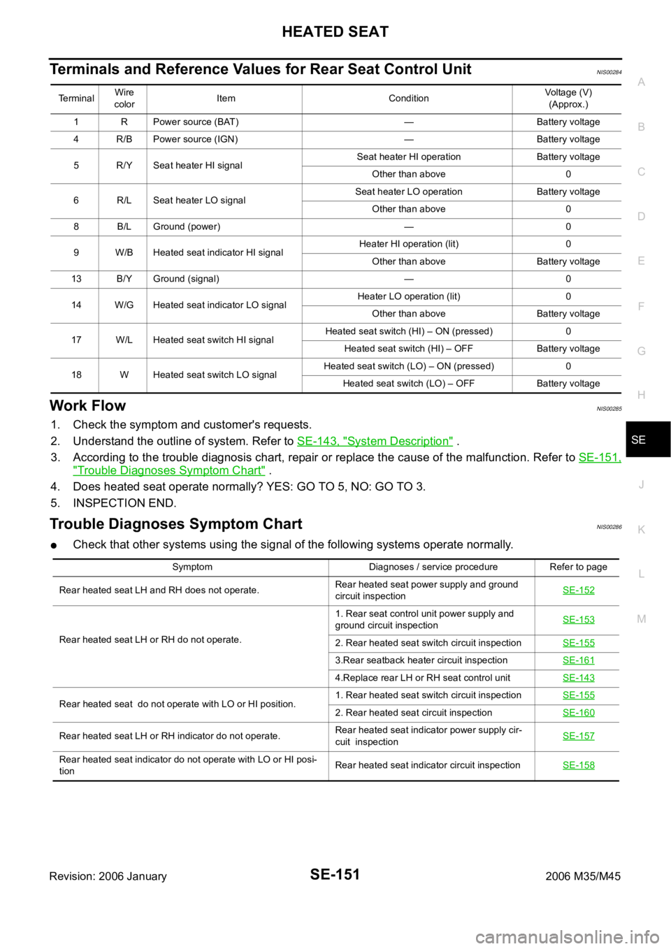
Terminals and Reference Values for Rear Seat Control UnitNIS00284
Work FlowNIS00285
1. Check the symptom and customer's requests.
2. Understand the outline of system. Refer to SE-143, "
System Description" .
3. According to the trouble diagnosis chart, repair or replace the cause of the malfunction. Refer to SE-151,
"Trouble Diagnoses Symptom Chart" .
4. Does heated seat operate normally? YES: GO TO 5, NO: GO TO 3.
5. INSPECTION END.
Trouble Diagnoses Symptom ChartNIS00286
Check that other systems using the signal of the following systems operate normally.
Te r m i n a lWire
colorItem ConditionVoltage (V)
(Approx.)
1 R Power source (BAT) — Battery voltage
4 R/B Power source (IGN) — Battery voltage
5 R/Y Seat heater HI signalSeat heater HI operation Battery voltage
Other than above 0
6 R/L Seat heater LO signalSeat heater LO operation Battery voltage
Other than above 0
8 B/L Ground (power) — 0
9 W/B Heated seat indicator HI signalHeater HI operation (lit) 0
Other than above Battery voltage
13 B/Y Ground (signal) — 0
14 W/G Heated seat indicator LO signalHeater LO operation (lit) 0
Other than above Battery voltage
17 W/L Heated seat switch HI signalHeated seat switch (HI) – ON (pressed) 0
Heated seat switch (HI) – OFF Battery voltage
18 W Heated seat switch LO signalHeated seat switch (LO) – ON (pressed) 0
Heated seat switch (LO) – OFF Battery voltage
Symptom Diagnoses / service procedure Refer to page
Rear heated seat LH and RH does not operate.Rear heated seat power supply and ground
circuit inspectionSE-152
Rear heated seat LH or RH do not operate.1. Rear seat control unit power supply and
ground circuit inspectionSE-1532. Rear heated seat switch circuit inspectionSE-155
3.Rear seatback heater circuit inspectionSE-161
4.Replace rear LH or RH seat control unitSE-143
Rear heated seat do not operate with LO or HI position.1. Rear heated seat switch circuit inspectionSE-1552. Rear heated seat circuit inspectionSE-160
Rear heated seat LH or RH indicator do not operate.Rear heated seat indicator power supply cir-
cuit inspectionSE-157
Rear heated seat indicator do not operate with LO or HI posi-
tionRear heated seat indicator circuit inspectionSE-158
SE-152
HEATED SEAT
Revision: 2006 January2006 M35/M45
Rear Heated Seat Power Supply and Ground Circuit InspectionNIS00287
1. CHECK FUSIBLE LINK AND FUSE
Check 50A fusible link (letter F located in the fuse and fusible link box).
Check 15A fuse (No.38, located in fuse block).
Check circuit breaker.
NOTE:
Refer to SE-143, "
Component Parts and Harness Connector Location" .
OK or NG
OK >> GO TO 2.
NG >> If fuse or circuit breaker is blown, be sure to eliminate cause of malfunction before installing new
fuse or new circuit breaker, refer to PG-3, "
POWER SUPPLY ROUTING CIRCUIT" .
2. CHECK HEATED SEAT RELAY POWER SUPPLY CIRCUIT
1. Turn ignition switch OFF.
2. Check voltage between IPDM E/R (heated seat relay) connector
and ground.
OK or NG
OK >> GO TO 3.
NG >> Repair or replace harness between fuse block (J/B) and IPDM E/R (heated seat relay).
3. CHECK HEATED SEAT RELAY GROUND CIRCUIT
1. Disconnect IPDM E/R (heated seat relay) connector.
2. Check continuity between IPDM E/R (heated seat relay) con-
nector and ground.
OK or NG
OK >> Check the condition of the harness and connector.
NG >> Repair or replace harness between IPDM E/R (heated
seat relay) and ground.
Terminal
Voltage (V)
(Approx.) (+)
(–) IPDM E/R
(heated seat relay)
connectorTerminal
E6 14 Ground Battery voltage
PIIB5995E
Te r m i n a l
Continuity IPDM E/R
(heated seat relay)
connectorTerminal
Ground
E9 54 Yes
PIIB5996E
HEATED SEAT
SE-153
C
D
E
F
G
H
J
K
L
MA
B
SE
Revision: 2006 January2006 M35/M45
Rear Seat Control Unit Power Supply and Ground Circuit InspectionNIS00288
1. CHECK REAR SEAT CONTROL UNIT POWER SUPPLY CIRCUIT (BAT)
1. Turn ignition switch OFF.
2. Check voltage between rear seat control unit connector and
ground.
OK or NG
OK >> GO TO 2.
NG >> Repair or replace harness between circuit breaker and rear seat control unit.
2. CHECK REAR SEAT CONTROL UNIT POWER SUPPLY CIRCUIT (IGN)
1. Turn ignition switch ON.
2. Check voltage between rear seat control unit connector and
ground.
OK or NG
OK >> GO TO 4.
NG >> GO TO 3.
Terminal
Voltage (V)
(Approx.) (+)
(–)
Rear seat control
unit connectorTerminal
B303 (LH)
B353 (RH)1 Ground Battery voltage
PIIB5997E
Terminal
Voltage (V)
(Approx.) (+)
(–)
Rear seat control
unit connectorTerminal
B303 (LH)
B353 (RH)4 Ground Battery voltage
PIIB5998E
SE-154
HEATED SEAT
Revision: 2006 January2006 M35/M45
3. CHECK REAR SEAT CONTROL UNIT HARNESS
1. Turn ignition switch OFF.
2. Disconnect IPDM E/R (heated seat relay) and rear seat control unit connector.
3. Check continuity between IPDM E/R (heated seat relay) con-
nector and rear seat control unit connector.
4. Check continuity between rear seat control unit connector and
ground.
OK or NG
OK >> GO TO 4.
NG >> Repair or replace harness between rear seat control unit and IPDM E/R (heated seat relay).
4. CHECK REAR SEAT CONTROL UNIT GROUND CIRCUIT
1. Turn ignition switch OFF.
2. Disconnect rear seat control unit connector.
3. Check continuity between rear seat control unit connector and
ground.
OK or NG
OK >> Rear seat control unit power supply and ground circuit is OK.
NG >> Repair or replace harness between rear seat control unit and ground.
AB
Continuity
Rear seat control
unit connectorTe r m i n a lIPDM E/R
(heated seat relay)
connectorTerminal
B303 (LH)
4E6 12
Ye s
B353 (RH) E5 9
A
GroundContinuity
Rear seat control unit connector Terminal
B303 (LH)
B353 (RH)4No
PIIB5999E
Te r m i n a l
Continuity
Rear seat control
unit connectorTerminal
Ground B303 (LH)
B353 (RH)8
Ye s
B304 (LH)
B354 (RH)13
PIIB6000E
HEATED SEAT
SE-155
C
D
E
F
G
H
J
K
L
MA
B
SE
Revision: 2006 January2006 M35/M45
Rear Heated Seat Switch Circuit InspectionNIS00289
1. CHECK REAR HEATED SEAT SWITCH POWER SUPPLY-1
1. Turn ignition switch ON.
2. Check voltage between rear seat control unit connector and
ground.
OK or NG
OK >> Rear heated seat switch circuit is OK.
NG >> GO TO 2.
2. CHECK REAR HEATED SEAT SWITCH HARNESS
1. Turn ignition switch OFF.
2. Disconnect rear heated seat switch and rear seat control unit connector.
3. Check continuity between rear heated seat switch connector
and rear seat control unit connector.
4. Check continuity between rear seat control unit connector and
ground.
OK or NG
OK >> GO TO 3.
NG >> Replace or replace harness between rear seat control unit and rear heated seat switch.
Terminal
ConditionVoltage (V)
(Approx.) (+)
(–) Rear seat
control unit
connectorTerminal
B304 (LH)
B354 (RH)17
GroundRear heated
seat switch HIGH 0
Other than above. 5
18Rear heated
seat switchLOW 0
Other than above. 5
PIIB6001E
AB
Continuity
Rear seat control
unit connectorTerminalRear heated seat
switch connectorTerminal
B304 (LH)
B354 (RH)17
B507 (LH)
B558 (RH)1
Ye s
18 2
A
GroundContinuity
Rear seat control unit connector Terminal
B304 (LH)
B354 (RH)17
No
18
PIIB6002E


 is LOW position, ground is suppled
to rear seat control unit terminal 18,
through rear heated seat switch te")


 and rear seat control unit connect")
