2006 INFINITI M35 ground
[x] Cancel search: groundPage 4723 of 5621

LT-296
ILLUMINATION
Revision: 2006 January2006 M35/M45
ILLUMINATION OPERATION BY LIGHTING SWITCH
With the lighting switch in the 1ST or 2ND position (or if the auto light system is activated), the BCM receives
input signal requesting the illumination lamps to illuminate. This input signal is communicated to the IPDM E/R
across the CAN communication lines. The CPU located in the IPDM E/R controls the tail lamp relay coil,
which, when energized, directs power
through IPDM E/R terminal 21
to combination meter terminal 13
to LDW switch (illumination) terminal 5 (with lane departure warning)
to VDC off switch (illumination) terminal 3
to trunk lid opener switch (illumination) terminal 3
to combination switch (spiral cable) terminal 24
to door mirror remote control switch (illumination) terminal 16
to AFS switch (illumination) terminal 5 (with AFS)
to rear sunshade front switch (illumination) terminal 5 (with rear control switch)
to A/T illumination terminal 1
to snow mode switch (illumination) terminal 5 (AWD models)
to rear control cancel switch (illumination) terminal 4 (with rear control switch)
to clock terminal 3
to multifunction switch terminal 3
to audio unit terminal 9
to DVD player terminal 18 (with DVD player)
to NAVI control unit terminal 61 (with navigation system)
to AV control unit terminal 61 (without navigation system)
to climate controlled seat switch driver side (illumination) terminal 7 (with climate controlled seat)
to climate controlled seat switch passenger side (illumination) terminal 7 (with climate controlled seat)
to ashtray illumination (rear LH) terminal 1
to ashtray illumination (rear RH) terminal 1
to illumination control switch terminal 1
to cigarette lighter socket (illumination) terminal 2
to map lamp (illumination) terminal 8
to power window main switch illumination terminal 1
to glove box lamp terminal 1
to rear control switch terminal 2
to rear power seat switch RH (illumination) terminal 4 (with rear control switch)
to rear heated seat switch RH (illumination) terminal 7 (with rear control switch)
to rear sunshade cancel relay terminal 6 (with rear control switch)
to automatic return cancel switch (illumination) terminal 4 (with rear control switch)
to rear power seat switch LH (illumination) terminal 4 (with rear control switch) and
to rear heated seat switch LH (illumination) terminal 7 (with rear control switch),
through Intelligent Key unit terminal 12
to push button ignition switch (illumination) terminal 3.
Ground is supplied
to combination meter terminal 14
to combination meter terminal 9, 10 and 11
to push button ignition switch (illumination) terminal 2
to LDW switch (illumination) terminal 4 (with lane departure warning)
to VDC off switch (illumination) terminal 4
to trunk lid opener switch (illumination) terminal 4
to combination switch (spiral cable) terminal 25
Page 4724 of 5621

ILLUMINATION
LT-297
C
D
E
F
G
H
I
J
L
MA
B
LT
Revision: 2006 January2006 M35/M45
to door mirror remote control switch (illumination) terminal 15
to AFS switch (illumination) terminal 6 (with AFS)
to rear sunshade front switch (illumination) terminal 6 (with rear control switch)
to A/T illumination terminal 2
to snow mode switch (illumination) terminal 6 (ADW models)
to rear control cancel switch (illumination) terminal 5 (with rear control switch)
to clock terminal 4
to multifunction switch terminal 4
to audio unit terminal 8
to DVD player terminal 17 (With DVD player)
to climate controlled seat switch driver side (illumination) terminal 8 (with climate controlled seat) and
to climate controlled seat switch passenger side (illumination) terminal 8 (with climate controlled seat)
through illumination control switch terminal 2
to illumination control switch terminal 3
through grounds M16 and M70,
to cigarette lighter socket (illumination) terminal 1
to map lamp (illumination) terminal 4
to power window main switch illumination terminal 2 and
to glove box lamp terminal 2
through grounds M16 and M70,
to ashtray illumination (rear LH) terminal 2
to ashtray illumination (rear RH) terminal 2
to automatic return cancel switch (illumination) terminal 2 (With rear control switch)
to rear power seat switch LH (illumination) terminal 3 (With rear control switch)
to rear heated seat switch LH (illumination) terminal 8 (With rear control switch)
through grounds B5, B40 and B131,
through rear sunshade cancel relay terminal 7(With rear control switch)
to rear sunshade rear switch (illumination) terminal 7 (With rear control switch)
through grounds B5, B40, B131 and B559.
to rear control switch terminal 4
to rear power seat switch RH (illumination) terminal 3 (With rear control switch)
to rear heated seat switch RH (illumination) terminal 8 (With rear control switch)
through grounds B5, B40, B131 and B559.
With power and ground supplied, illumination lamps illuminate.
EXTERIOR LAMP BATTERY SAVER CONTROL
BCM activates the exterior lamp battery saver control function and turns off the exterior lamps to prevent bat-
tery from over discharge when the combination switch (lighting switch) is in 1ST or 2ND position and/or the
front fog lamp switch ON and the door lock operation is performed by keyless entry system.
CAN Communication System DescriptionNKS003TI
CAN (Controller Area Network) is a serial communication line for real time application. It is an on-vehicle mul-
tiplex communication line with high data communication speed and excellent error detection ability. Many elec-
tronic control units are equipped onto a vehicle, and each control unit shares information and links with other
control units during operation (not independent). In CAN communication, control units are connected with 2
communication lines (CAN H line, CAN L line) allowing a high rate of information transmission with less wiring.
Each control unit transmits/receives data but selectively reads required data only.
CAN Communication UnitNKS003TJ
Refer to LAN-34, "CAN Communication Unit" .
Page 4828 of 5621

PG-1
POWER SUPPLY, GROUND & CIRCUIT ELEMENTS
K ELECTRICAL
CONTENTS
C
D
E
F
G
H
I
J
L
M
SECTION PG
A
B
PG
Revision: 2006 January2006 M35/M45
POWER SUPPLY, GROUND & CIRCUIT ELEMENTS
POWER SUPPLY ROUTING CIRCUIT ...................... 3
Schematic ................................................................ 3
Wiring Diagram — POWER — ................................. 5
BATTERY POWER SUPPLY — IGNITION SW.
IN ANY POSITION ................................................ 5
ACCESSORY POWER SUPPLY — IGNITION
SW. IN “ACC” OR “ON” ........................................ 11
IGNITION POWER SUPPLY — IGNITION SW.
IN “ON” AND/OR “START” .................................. 12
Fuse ....................................................................... 17
Fusible Link ............................................................ 17
Circuit Breaker ....................................................... 17
IPDM E/R (INTELLIGENT POWER DISTRIBUTION
MODULE ENGINE ROOM) ...................................... 18
System Description ................................................ 18
SYSTEMS CONTROLLED BY IPDM E/R ........... 18
CAN COMMUNICATION LINE CONTROL ......... 18
IPDM E/R STATUS CONTROL ........................... 19
CAN Communication System Description .............. 19
CAN Communication Unit ...................................... 19
Function of Detecting Ignition Relay Malfunction ... 19
CONSULT-II Function (IPDM E/R) ......................... 20
CONSULT-II BASIC OPERATION ....................... 20
SELF-DIAG RESULTS ........................................ 21
DATA MONITOR ................................................. 22
CAN DIAG SUPPORT MNTR ............................. 23
ACTIVE TEST ..................................................... 23
Auto Active Test ..................................................... 24
DESCRIPTION .................................................... 24
OPERATION PROCEDURE ............................... 24
INSPECTION IN AUTO ACTIVE TEST MODE ... 25
Schematic .............................................................. 28
IPDM E/R Terminal Arrangement ........................... 29
Check IPDM E/R Power Supply and Ground Circuit ... 30
Inspection with CONSULT-II (Self-Diagnosis) ........ 31
Removal and Installation of IPDM E/R ................... 31
REMOVAL ........................................................
... 31
INSTALLATION ................................................... 32
PDU (POWER DISTRIBUTION UNIT) ...................... 33
Component Parts and Harness Connector Location ... 33System Description ................................................. 33
PUSH-BUTTON IGNITION SWITCH OPERAT-
ING PROCEDURE .............................................. 33
Wiring Diagram — PDU — ..................................... 35
Terminals and Reference Value for Intelligent Key
Unit ......................................................................... 37
Terminals and Reference Value for PDU ................ 38
Work Flow ............................................................... 38
Trouble Diagnosis Symptom Chart ......................... 39
Check CAN Communication System ...................... 39
Check PDU Power Supply and Ground Circuit ...... 40
Check Push-Button Ignition Switch (Ignition Switch)
System .................................................................... 40
Check Push-Button Ignition Switch (Indicator Cir-
cuit) System ............................................................ 42
PDU Communication Circuit System 1 ................... 43
PDU Communication Circuit System 2 ................... 44
Removal and Installation of PDU ............................ 45
REMOVAL ........................................................
... 45
INSTALLATION ................................................... 45
GROUND ................................................................... 46
Ground Distribution ................................................. 46
MAIN HARNESS ................................................. 46
ENGINE ROOM HARNESS ................................ 51
ENGINE CONTROL HARNESS/VQ ENGINE
MODELS ............................................................. 55
ENGINE CONTROL HARNESS/VK ENGINE
MODELS ............................................................. 56
BODY HARNESS ................................................ 57
BODY NO. 2 HARNESS ..................................... 62
HARNESS ................................................................. 63
Harness Layout ...................................................... 63
HOW TO READ HARNESS LAYOUT ................. 63
OUTLINE ............................................................. 64
MAIN HARNESS ................................................. 65
NAVIGATION SUB-HARNESS & A/C HARNESS ... 70
ENGINE ROOM HARNESS ................................ 71
ENGINE CONTROL HARNESS (VQ ENGINE) ... 78
ENGINE CONTROL HARNESS (VK ENGINE) ... 81
BODY HARNESS ................................................ 84
Page 4853 of 5621

PG-26
IPDM E/R (INTELLIGENT POWER DISTRIBUTION MODULE ENGINE ROOM)
Revision: 2006 January2006 M35/M45
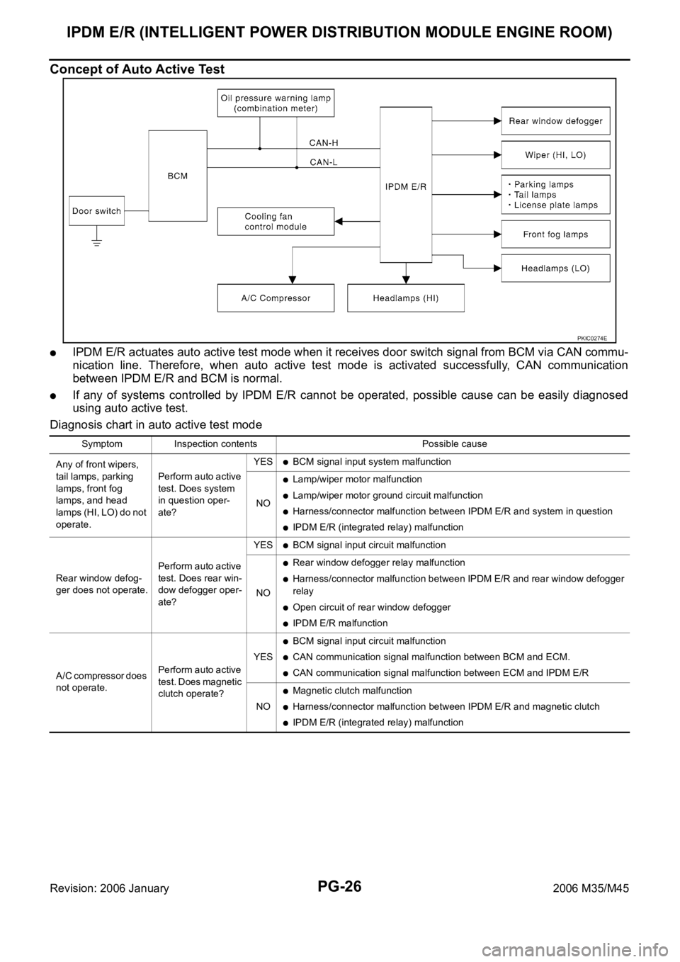
Concept of Auto Active Test
IPDM E/R actuates auto active test mode when it receives door switch signal from BCM via CAN commu-
nication line. Therefore, when auto active test mode is activated successfully, CAN communication
between IPDM E/R and BCM is normal.
If any of systems controlled by IPDM E/R cannot be operated, possible cause can be easily diagnosed
using auto active test.
Diagnosis chart in auto active test mode
PKIC0274E
Symptom Inspection contents Possible cause
Any of front wipers,
tail lamps, parking
lamps, front fog
lamps, and head
lamps (HI, LO) do not
operate.Perform auto active
test. Does system
in question oper-
ate?YES
BCM signal input system malfunction
NO
Lamp/wiper motor malfunction
Lamp/wiper motor ground circuit malfunction
Harness/connector malfunction between IPDM E/R and system in question
IPDM E/R (integrated relay) malfunction
Rear window defog-
ger does not operate.Perform auto active
test. Does rear win-
dow defogger oper-
ate?YES
BCM signal input circuit malfunction
NO
Rear window defogger relay malfunction
Harness/connector malfunction between IPDM E/R and rear window defogger
relay
Open circuit of rear window defogger
IPDM E/R malfunction
A/C compressor does
not operate.Perform auto active
test. Does magnetic
clutch operate?YES
BCM signal input circuit malfunction
CAN communication signal malfunction between BCM and ECM.
CAN communication signal malfunction between ECM and IPDM E/R
NO
Magnetic clutch malfunction
Harness/connector malfunction between IPDM E/R and magnetic clutch
IPDM E/R (integrated relay) malfunction
Page 4857 of 5621

PG-30
IPDM E/R (INTELLIGENT POWER DISTRIBUTION MODULE ENGINE ROOM)
Revision: 2006 January2006 M35/M45
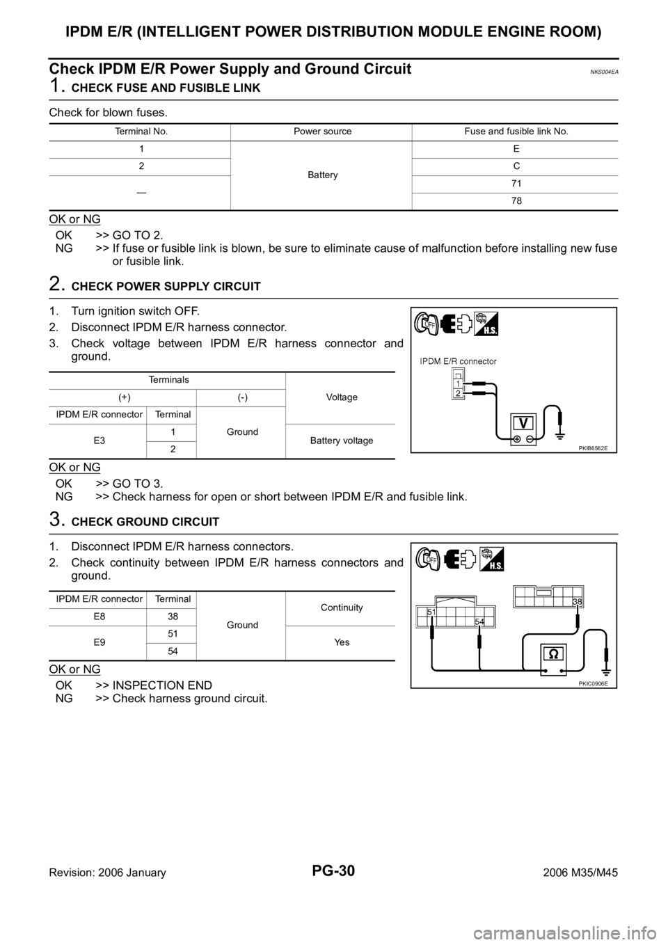
Check IPDM E/R Power Supply and Ground CircuitNKS004EA
1. CHECK FUSE AND FUSIBLE LINK
Check for blown fuses.
OK or NG
OK >> GO TO 2.
NG >> If fuse or fusible link is blown, be sure to eliminate cause of malfunction before installing new fuse
or fusible link.
2. CHECK POWER SUPPLY CIRCUIT
1. Turn ignition switch OFF.
2. Disconnect IPDM E/R harness connector.
3. Check voltage between IPDM E/R harness connector and
ground.
OK or NG
OK >> GO TO 3.
NG >> Check harness for open or short between IPDM E/R and fusible link.
3. CHECK GROUND CIRCUIT
1. Disconnect IPDM E/R harness connectors.
2. Check continuity between IPDM E/R harness connectors and
ground.
OK or NG
OK >> INSPECTION END
NG >> Check harness ground circuit.
Terminal No. Power source Fuse and fusible link No.
1
BatteryE
2C
—71
78
Terminals
Vo l ta g e (+) (-)
IPDM E/R connector Terminal
Ground
E31
Battery voltage
2
PKIB6562E
IPDM E/R connector Terminal
GroundContinuity
E8 38
E951
Ye s
54
PKIC0906E
Page 4864 of 5621

PDU (POWER DISTRIBUTION UNIT)
PG-37
C
D
E
F
G
H
I
J
L
MA
B
PG
Revision: 2006 January2006 M35/M45
Terminals and Reference Value for Intelligent Key UnitNKS004EG
Te r m i -
nalWire
ColorItemCondition
Voltage (V)
Approx. Ignition
Switch
PositionOperation or Conditions
1 SB Power source (Fuse) LOCK — Battery voltage
3 Y IPDM E/R status signal —Engine starting (During Cranking) 5
Other than above 2
8WPush-button ignition
switch
(LOCK LED)LOCK Push-button ignition switch is in LOCK position 0
—Push-button ignition switch is in any position
(Except LOCK position)1.2
9LPush-button ignition
switch
(ACC LED)ACC Push-button ignition switch is in ACC position 0
—Push-button ignition switch is in any position
(Except ACC position)1.2
10 VPush-button ignition
switch
(ON LED)ON Push-button ignition switch is in ON position 0
—Push-button ignition switch is in any position
(Except ON position)1.2
20 B Ground — — 0
30 L/W Ignition switch (ACC) ACC — Battery voltage
31 GR Ignition switch (ON) ON — Battery voltage
34 R PDU feedback signal LOCKPush-button ignition switch is in LOCK state, 30 sec-
onds after all doors closed1
Other than above 0
36 W Ignition signal 2LOCK — Battery voltage
ACC — Battery voltage
ON — 0
37 P CAN-L — — —
38 L CAN-H — — —
39 BR/W Push switch —Depress push-button ignition switch 0
Unpress push-button ignition switch Battery voltage
40 B Ground — — 0
41 Y Power source (Fuse) LOCK — Battery voltage
42 P PDU wake up signal LOCKPush-button ignition switch is in LOCk state, 30 sec-
onds after all doors closedBattery voltage
Other than above 0
44 BR Ignition signal 1LOCK — Battery voltage
ACC — Battery voltage
ON — 0
45 SB ACC signalLOCK — Battery voltage
ACC — 0
ON — 0
56 B Ground — — 0
57 L Power source (Fuse) LOCK — Battery voltage
72 B Ground — — 0
Page 4865 of 5621

PG-38
PDU (POWER DISTRIBUTION UNIT)
Revision: 2006 January2006 M35/M45
Terminals and Reference Value for PDUNKS004EH
Work FlowNKS004EI
1. Check the symptom and customer's requests.
2. Understand outline of system. Refer to PG-33, "
System Description" .
3. Confirm that Intelligent Key system operates normally.
Refer to BL-24, "
POWER DOOR LOCK SYSTEM" .
4. Repair or replace any malfunctioning parts.
Refer to PG-39, "
Trouble Diagnosis Symptom Chart" .
5. INSPECTION END
Te r m i -
nalWire
ColorItemCondition
Voltage (V)
Approx. Ignition
Switch
PositionOperation or Conditions
1 P PDU wake up signal LOCKPush-button ignition switch is in LOCK state, 30 sec-
onds after all doors closeBattery voltage
Other than above 0
4 BR Ignition signal 1LOCK — Battery voltage
ACC — Battery voltage
ON — 0
5 W Ignition signal 2LOCK — Battery voltage
ACC — Battery voltage
ON — 0
8 SB ACC signalLOCK — Battery voltage
ACC — 0
ON — 0
10 B Ground — — 0
11 Y IPDM E/R status signal —Engine starting (During Cranking) 5
Other than above 2
12 R PDU feedback signal LOCKPush-button ignition switch is in LOCK state, 30 sec-
onds after all doors close1
Other than above 0
14 SB Power source (Fuse) LOCK — Battery voltage
15 L Power source (F/L) LOCK — Battery voltage
16 W ACC power outputLOCK — 0
ACC — Battery voltage
ON — Battery voltage
17 G Power source (Fuse) LOCK — Battery voltage
18 BR ON power outputLOCK — 0
ACC — 0
ON — Battery voltage
Page 4866 of 5621

PDU (POWER DISTRIBUTION UNIT)
PG-39
C
D
E
F
G
H
I
J
L
MA
B
PG
Revision: 2006 January2006 M35/M45
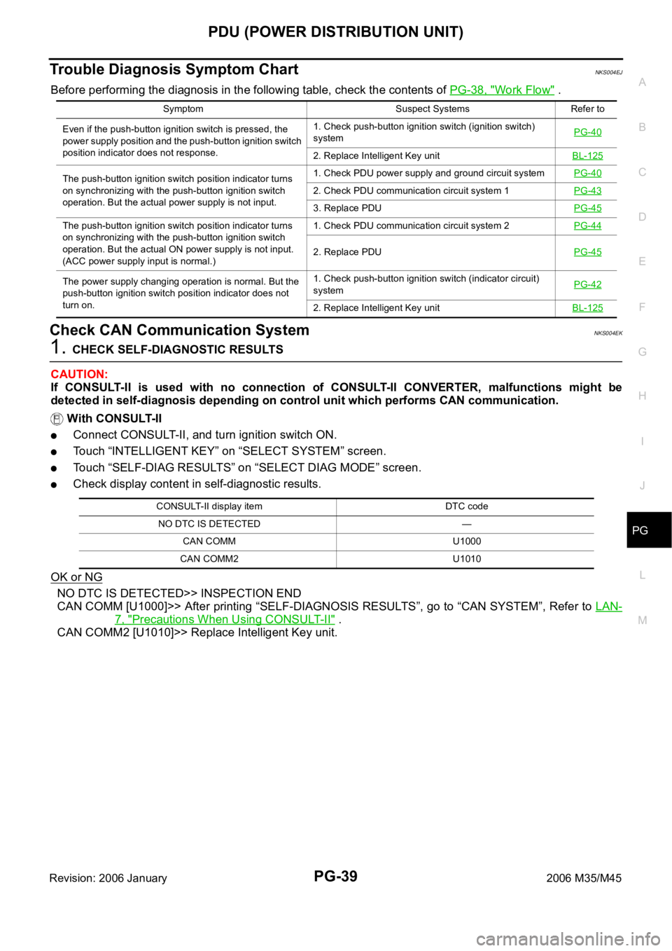
Trouble Diagnosis Symptom ChartNKS004EJ
Before performing the diagnosis in the following table, check the contents of PG-38, "Work Flow" .
Check CAN Communication SystemNKS004EK
1. CHECK SELF-DIAGNOSTIC RESULTS
CAUTION:
If CONSULT-II is used with no connection of CONSULT-II CONVERTER, malfunctions might be
detected in self-diagnosis depending on control unit which performs CAN communication.
With CONSULT-II
Connect CONSULT-II, and turn ignition switch ON.
Touch “INTELLIGENT KEY” on “SELECT SYSTEM” screen.
Touch “SELF-DIAG RESULTS” on “SELECT DIAG MODE” screen.
Check display content in self-diagnostic results.
OK or NG
NO DTC IS DETECTED>> INSPECTION END
CAN COMM [U1000]>> After printing “SELF-DIAGNOSIS RESULTS”, go to “CAN SYSTEM”, Refer to LAN-
7, "Precautions When Using CONSULT-II" .
CAN COMM2 [U1010]>> Replace Intelligent Key unit.
Symptom Suspect Systems Refer to
Even if the push-button ignition switch is pressed, the
power supply position and the push-button ignition switch
position indicator does not response.1. Check push-button ignition switch (ignition switch)
systemPG-40
2. Replace Intelligent Key unitBL-125
The push-button ignition switch position indicator turns
on synchronizing with the push-button ignition switch
operation. But the actual power supply is not input.1. Check PDU power supply and ground circuit systemPG-40
2. Check PDU communication circuit system 1PG-43
3. Replace PDUPG-45
The push-button ignition switch position indicator turns
on synchronizing with the push-button ignition switch
operation. But the actual ON power supply is not input.
(ACC power supply input is normal.)1. Check PDU communication circuit system 2PG-44
2. Replace PDUPG-45
The power supply changing operation is normal. But the
push-button ignition switch position indicator does not
turn on.1. Check push-button ignition switch (indicator circuit)
systemPG-42
2. Replace Intelligent Key unitBL-125
CONSULT-II display item DTC code
NO DTC IS DETECTED —
CAN COMM U1000
CAN COMM2 U1010