Page 4648 of 5621

TURN SIGNAL AND HAZARD WARNING LAMPS
LT-221
C
D
E
F
G
H
I
J
L
MA
B
LT
Revision: 2006 January2006 M35/M45
Preliminary CheckNKS003RS
CHECK POWER SUPPLY AND GROUND CIRCUIT
1. CHECK FUSE
Check for blown fuses.
Refer to LT-215, "Wiring Diagram — TURN —" .
OK or NG
OK >> GO TO 2.
NG >> If fuse or fusible link is blown, be sure to eliminate cause of malfunction before installing new fuse
or fusible link. Refer to PG-3, "
POWER SUPPLY ROUTING CIRCUIT" .
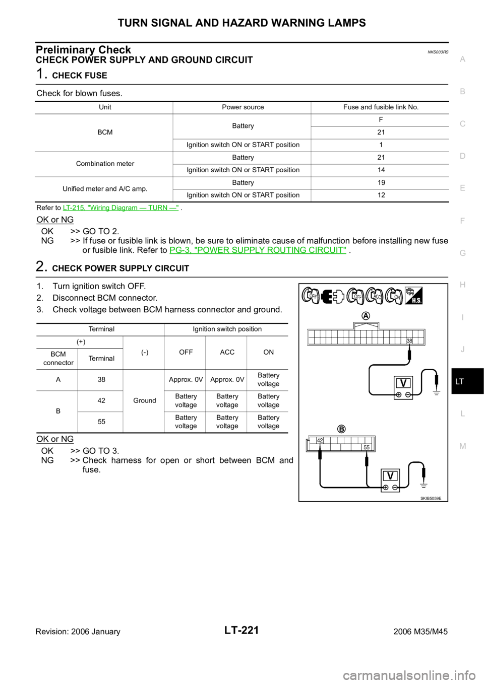
2. CHECK POWER SUPPLY CIRCUIT
1. Turn ignition switch OFF.
2. Disconnect BCM connector.
3. Check voltage between BCM harness connector and ground.
OK or NG
OK >> GO TO 3.
NG >> Check harness for open or short between BCM and
fuse.
Unit Power source Fuse and fusible link No.
BCMBatteryF
21
Ignition switch ON or START position 1
Combination meterBattery 21
Ignition switch ON or START position 14
Unified meter and A/C amp.Battery 19
Ignition switch ON or START position 12
Terminal Ignition switch position
(+)
(-) OFF ACC ON
BCM
connectorTerminal
A38
GroundApprox. 0V Approx. 0VBattery
voltage
B42Battery
voltageBattery
voltageBattery
voltage
55Battery
voltageBattery
voltageBattery
voltage
SKIB5059E
Page 4649 of 5621
LT-222
TURN SIGNAL AND HAZARD WARNING LAMPS
Revision: 2006 January2006 M35/M45
3. CHECK GROUND CIRCUIT
Check continuity between BCM harness connector and ground.
OK or NG
OK >> INSPECTION END
NG >> Check harness ground circuit.
BCM connector Terminal
GroundContinuity
M2 52 Yes
SKIB5125E
Page 4650 of 5621

TURN SIGNAL AND HAZARD WARNING LAMPS
LT-223
C
D
E
F
G
H
I
J
L
MA
B
LT
Revision: 2006 January2006 M35/M45
CONSULT-II Functions (BCM)NKS003RT
CONSULT-II can display each diagnostic item using the diagnostic test mode shown following.
CONSULT-II BASIC OPERATION
CAUTION:
If CONSULT-II is used with no connection of CONSULT-II CONVERTER, malfunctions might be
detected in self-diagnosis depending on control unit which carry out CAN communication.
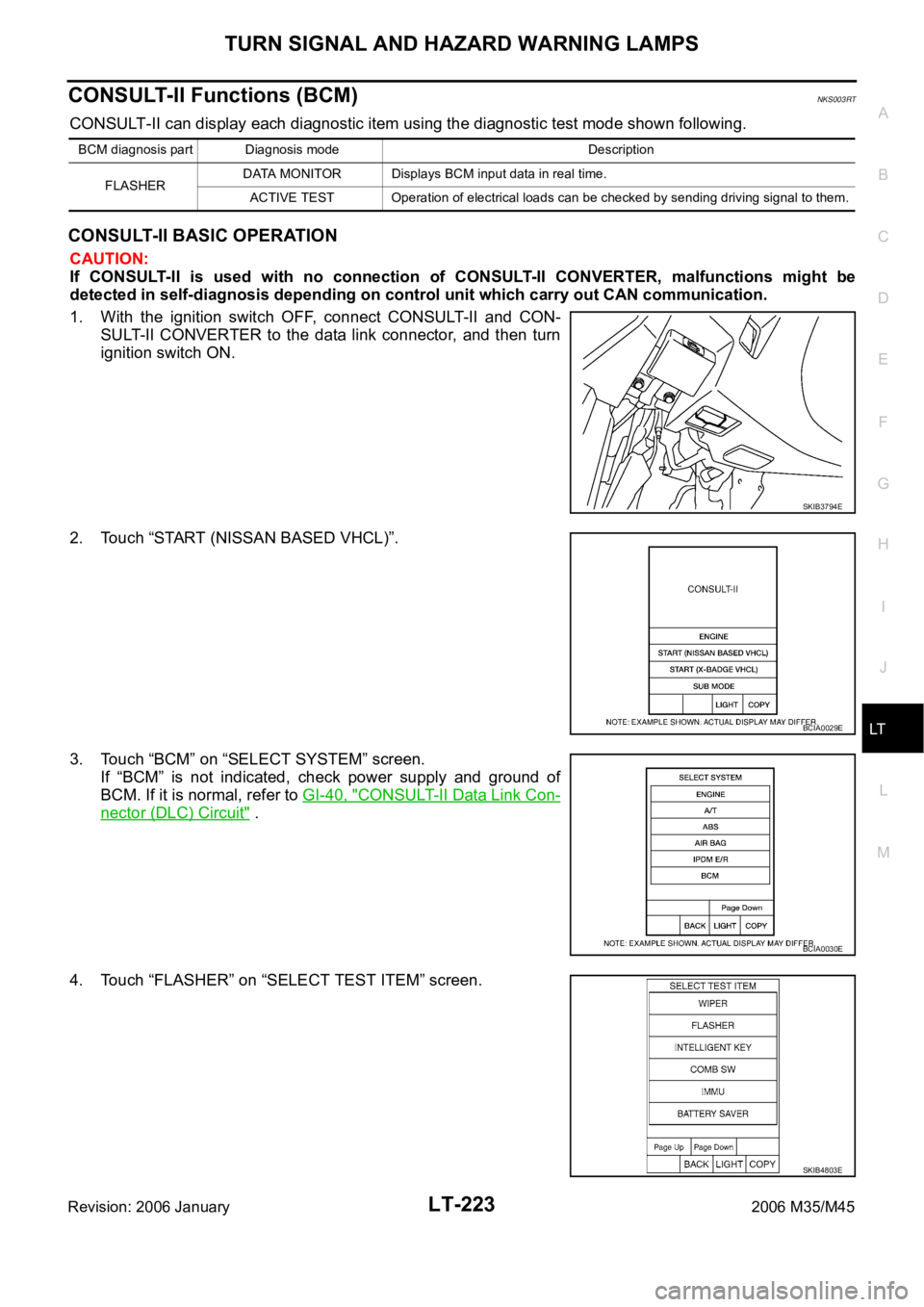
1. With the ignition switch OFF, connect CONSULT-II and CON-
SULT-II CONVERTER to the data link connector, and then turn
ignition switch ON.
2. Touch “START (NISSAN BASED VHCL)”.
3. Touch “BCM” on “SELECT SYSTEM” screen.
If “BCM” is not indicated, check power supply and ground of
BCM. If it is normal, refer to GI-40, "
CONSULT-II Data Link Con-
nector (DLC) Circuit" .
4. Touch “FLASHER” on “SELECT TEST ITEM” screen.
BCM diagnosis part Diagnosis mode Description
FLASHERDATA MONITOR Displays BCM input data in real time.
ACTIVE TEST Operation of electrical loads can be checked by sending driving signal to them.
SKIB3794E
BCIA0029E
BCIA0030E
SKIB4803E
Page 4653 of 5621

LT-226
TURN SIGNAL AND HAZARD WARNING LAMPS
Revision: 2006 January2006 M35/M45
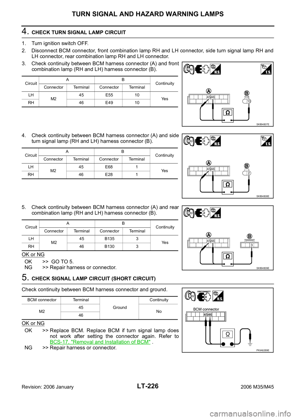
4. CHECK TURN SIGNAL LAMP CIRCUIT
1. Turn ignition switch OFF.
2. Disconnect BCM connector, front combination lamp RH and LH connector, side turn signal lamp RH and
LH connector, rear combination lamp RH and LH connector.
3. Check continuity between BCM harness connector (A) and front
combination lamp (RH and LH) harness connector (B).
4. Check continuity between BCM harness connector (A) and side
turn signal lamp (RH and LH) harness connector (B).
5. Check continuity between BCM harness connector (A) and rear
combination lamp (RH and LH) harness connector (B).
OK or NG
OK >> GO TO 5.
NG >> Repair harness or connector.
5. CHECK SIGNAL LAMP CIRCUIT (SHORT CIRCUIT)
Check continuity between BCM harness connector and ground.
OK or NG
OK >> Replace BCM. Replace BCM if turn signal lamp does
not work after setting the connector again. Refer to
BCS-17, "
Removal and Installation of BCM" .
NG >> Repair harness or connector.
CircuitAB
Continuity
Connector Terminal Connector Terminal
LH
M245 E55 10
Ye s
RH 46 E49 10
SKIB4807E
CircuitAB
Continuity
Connector Terminal Connector Terminal
LH
M245 E68 1
Ye s
RH 46 E28 1
SKIB4808E
CircuitAB
Continuity
Connector Terminal Connector Terminal
LH
M245 B135 3
Ye s
RH 46 B130 3
SKIB4809E
BCM connector Terminal
GroundContinuity
M245
No
46
PKIA6289E
Page 4654 of 5621

TURN SIGNAL AND HAZARD WARNING LAMPS
LT-227
C
D
E
F
G
H
I
J
L
MA
B
LT
Revision: 2006 January2006 M35/M45
Hazard Warning Lamp Does Not Operate But Turn Signal Lamp OperateNKS003RV
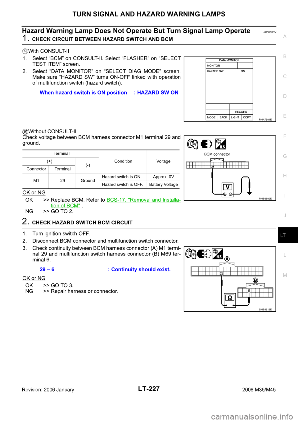
1. CHECK CIRCUIT BETWEEN HAZARD SWITCH AND BCM
With CONSULT-II
1. Select “BCM” on CONSULT-II. Select “FLASHER” on “SELECT
TEST ITEM” screen.
2. Select “DATA MONITOR” on “SELECT DIAG MODE” screen.
Make sure “HAZARD SW” turns ON-OFF linked with operation
of multifunction switch (hazard switch).
Without CONSULT-II
Check voltage between BCM harness connector M1 terminal 29 and
ground.
OK or NG
OK >> Replace BCM. Refer to BCS-17, "Removal and Installa-
tion of BCM" .
NG >> GO TO 2.
2. CHECK HAZARD SWITCH BCM CIRCUIT
1. Turn ignition switch OFF.
2. Disconnect BCM connector and multifunction switch connector.
3. Check continuity between BCM harness connector (A) M1 termi-
nal 29 and multifunction switch harness connector (B) M69 ter-
minal 6.
OK or NG
OK >> GO TO 3.
NG >> Repair harness or connector.When hazard switch is ON position : HAZARD SW ON
PKIA7601E
Terminal
Condition Voltage (+)
(-)
Connector Terminal
M1 29 GroundHazard switch is ON. Approx. 0V
Hazard switch is OFF. Battery Voltage
PKIB6809E
29 – 6 : Continuity should exist.
SKIB4812E
Page 4655 of 5621
LT-228
TURN SIGNAL AND HAZARD WARNING LAMPS
Revision: 2006 January2006 M35/M45
3. CHECK HAZARD SWITCH GROUND CIRCUIT
Check continuity between multifunction switch harness connector
terminal 14 and ground.
OK or NG
OK >> GO TO 4.
NG >> Repair harness or connector.
4. CHECK HAZARD SWITCH
Check continuity multifunction switch (hazard switch).
OK or NG
OK >> Replace BCM. Replace BCM if turn signal lamp does
not work after setting the connector again. Refer to
BCS-17, "
Removal and Installation of BCM" .
NG >> Replace multifunction switch. Refer to AV- 2 9 2 , "
Multifunction Switch" .
Turn Signal Indicator Lamp Does Not OperateNKS003RW
1. CHECK BULB
Check bulb of turn signal indicator lamp in combination meter.
OK or NG
OK >> Replace combination meter.
NG >> Replace indicator bulb.14 – Ground : Continuity should exist.
SKIB4813E
Multifunction switch
(Hazard switch)
Condition Continuity
Terminal
614Hazard switch is ON. Yes
Hazard switch is OFF. No
SKIB4814E
Page 4664 of 5621
COMBINATION SWITCH
LT-237
C
D
E
F
G
H
I
J
L
MA
B
LT
Revision: 2006 January2006 M35/M45
36 VCombination
switch output 1ONLighting, turn, wiper
switch
(Wiper dial position 4)
Any of several con-
ditions below
Turn signal switch
right
Turn signal switch left
Front wiper switch
MIST
Front wiper switch LO
Front washer switchApprox. 1.2V
OFF
(Wiper dial position 4)
Approx. 7.0 - 7.5V
38 WIgnition switch
(ON) ON — Battery voltage
39 L CAN
H — — —
40 P CAN
L — — —
42 PBattery power
supplyOFF — Battery voltage
52 B Ground ON — Approx. 0V
55 WBattery power
supplyOFF — Battery voltage Terminal
No.Wire
colorSignal nameMeasuring condition
Reference value
Ignition
switchOperation or condition
PKIB4958J
PKIB4960J
Page 4665 of 5621
LT-238
COMBINATION SWITCH
Revision: 2006 January2006 M35/M45
CONSULT-II Functions (BCM)NKS003S8
CONSULT-II can display each diagnostic item using the diagnostic test mode shown following.
CONSULT-II BASIC OPERATION
CAUTION:
If CONSULT-II is used with no connection of CONSULT-II CONVERTER, malfunctions might be
detected in self-diagnosis depending on control unit which carry out CAN communication.
1. With the ignition switch OFF, connect CONSULT-II and CON-
SULT-II CONVERTER to the data link connector, and then turn
ignition switch ON.
2. Touch “START (NISSAN BASED VHCL)”.
3. Touch “BCM” on “SELECT SYSTEM” screen.
If “BCM” is not indicated, check power supply and ground of
BCM. If it is normal, refer to GI-40, "
CONSULT-II Data Link Con-
nector (DLC) Circuit" .
4. Touch “COMB SW”.
BCM diagnosis part Diagnosis mode Description
COMB SW DATA MONITOR Displays BCM input data in real time.
SKIB3794E
BCIA0029E
BCIA0030E
SKIB4803E