2006 INFINITI M35 door lock
[x] Cancel search: door lockPage 1203 of 5621

BL-264
IVIS (INFINITI VEHICLE IMMOBILIZER SYSTEM-NATS)
Revision: 2006 January2006 M35/M45
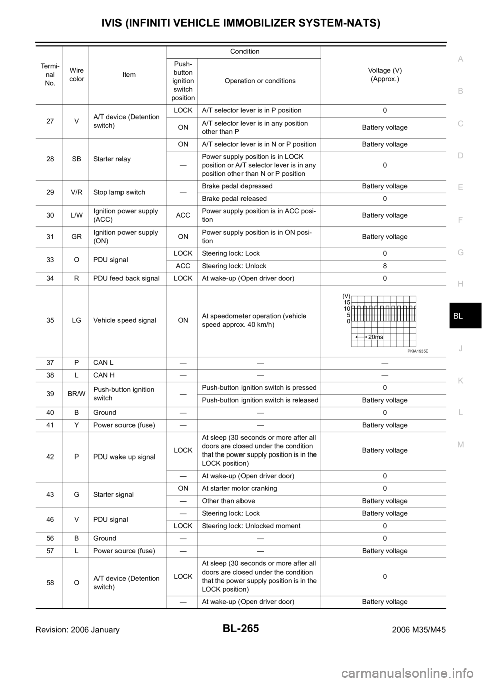
Terminals and Reference Value for Intelligent Key UnitNIS0020I
Te r m i -
nal
No.Wire
colorItemCondition
Voltage (V)
(Approx.) Push-
button
ignition
switch
positionOperation or conditions
1 SB Power source (fuse) — — Battery voltage
3YIPDM E/R current sig-
nalSTART At starter motor cranking 5
LOCK Any condition other than above 2
8WPush-button ignition
switch LOCK indicatorLOCKPower supply position is in LOCK
position0
—Power supply position is in any posi-
tion other than LOCK1.2
9LPush-button ignition
switch ACC indicatorACCPower supply position is in ACC posi-
tion0
—Power supply position is in any posi-
tion other than ACC1.2
10 VPush-button ignition
switch ON indicatorONPower supply position is in ON posi-
tion0
—Power supply position is in any posi-
tion other than ON1.2
11 P Stop lamp switch —Brake pedal depressed Battery voltage
Brake pedal released Battery voltage
12 L/RPush-button ignition
switch illumination—Push-button ignition switch illumina-
tion is turned on2.6
Push-button ignition switch illumina-
tion is turned off
(15 seconds or more after the driver
door is closed)0
13 LG/B Key slot illumination LOCKDriver door is opened under the condi-
tion that the Intelligent Key is inserted
into the key slot0
Battery voltage 0
Intelligent Key is removed from key
slot (when key slot illumination is
turned off)0
15 LGSteering lock unit
power sourceLOCK — Battery voltage
16 P/BSteering lock unit sig-
nalLOCK Steering lock: Lock Battery voltage
ACCSteering lock: Unlock
(Unlocked moment)0
17 OSteering lock unit con-
dition signal-1LOCK Steering lock: Lock 0
ACC
Steering lock: UnlockBattery voltage
ON Battery voltage
18 L/YSteering lock unit con-
dition signal-2LOCK Steering lock: Lock Battery voltage
ACC
Steering lock: Unlock0
ON 0
19 BR/Y Key switch LOCKIntelligent Key is inserted into key slot Battery voltage
Intelligent Key is removed from key
slot0
20 B Ground — — 0
Page 1204 of 5621

IVIS (INFINITI VEHICLE IMMOBILIZER SYSTEM-NATS)
BL-265
C
D
E
F
G
H
J
K
L
MA
B
BL
Revision: 2006 January2006 M35/M45
27 VA/T device (Detention
switch)LOCK A/T selector lever is in P position 0
ONA/T selector lever is in any position
other than PBattery voltage
28 SB Starter relayON A/T selector lever is in N or P position Battery voltage
—Power supply position is in LOCK
position or A/T selector lever is in any
position other than N or P position0
29 V/R Stop lamp switch —Brake pedal depressed Battery voltage
Brake pedal released 0
30 L/WIgnition power supply
(ACC)ACCPower supply position is in ACC posi-
tionBattery voltage
31 GRIgnition power supply
(ON)ONPower supply position is in ON posi-
tionBattery voltage
33 O PDU signalLOCK Steering lock: Lock 0
ACC Steering lock: Unlock 8
34 R PDU feed back signal LOCK At wake-up (Open driver door) 0
35 LG Vehicle speed signal ONAt speedometer operation (vehicle
speed approx. 40 km/h)
37 P CAN L — — —
38 L CAN H — — —
39 BR/WPush-button ignition
switch—Push-button ignition switch is pressed 0
Push-button ignition switch is released Battery voltage
40 B Ground — — 0
41 Y Power source (fuse) — — Battery voltage
42 P PDU wake up signalLOCKAt sleep (30 seconds or more after all
doors are closed under the condition
that the power supply position is in the
LOCK position)Battery voltage
— At wake-up (Open driver door) 0
43 G Starter signalON At starter motor cranking 0
— Other than above Battery voltage
46 V PDU signal— Steering lock: Lock Battery voltage
LOCK Steering lock: Unlocked moment 0
56 B Ground — — 0
57 L Power source (fuse) — — Battery voltage
58 OA/T device (Detention
switch)LOCKAt sleep (30 seconds or more after all
doors are closed under the condition
that the power supply position is in the
LOCK position)0
— At wake-up (Open driver door) Battery voltage Te r m i -
nal
No.Wire
colorItemCondition
Voltage (V)
(Approx.) Push-
button
ignition
switch
positionOperation or conditions
PKIA1935E
Page 1206 of 5621

IVIS (INFINITI VEHICLE IMMOBILIZER SYSTEM-NATS)
BL-267
C
D
E
F
G
H
J
K
L
MA
B
BL
Revision: 2006 January2006 M35/M45
Terminals and Reference Value for IPDM E/RNIS0020L
Terminals and Reference Value for PDUNIS0020M
38 WIgnition power supply
(ON or START)ONPower supply position is in ON posi-
tionBattery voltage
39 L CAN H — — —
40 P CAN L — — —
42 P Power source (fuse) — — Battery voltage
52 B Ground — — 0
55 WPower source (Fusible
link)— — Battery voltage Te r m i -
nal
No.Wire
colorItemCondition
Voltage (V)
(Approx.) Push-but-
ton igni-
tion
switch
positionOperation or conditions
Te r -
minal
No.Wire
ColorItemCondition
Voltage (V)
(Approx.) Push-
button
ignition
switch
positionOperation or conditions
4W/RStarter motor power
supplyLOCK — 0
START Starter motor is activating Battery voltage
49 L CAN H — — —
50 P CAN L — — —
53 GR/RA/T Shift position
signalONA/T shift position is P/ N posi-
tionBattery voltage
LOCK Other than above 0
Te r -
minal
No.Wire
colorItemCondition
Voltage (V)
(Approx.) Push-
button
ignition
switch
positionOperation or conditions
1 P Wake up signalLOCKSleep condition (30 seconds or more
after all doors are closed under the con-
dition that the power supply position is in
the LOCK position)Battery voltage
— Wake-up condition (Open driver door) 0
2 G Starter control signalON At starter motor cranking 0
— Any condition other than above Battery voltage
3GRSteering lock unit
power sourceLOCKPush-button ignition switch is pressed
under the condition that Intelligent Key is
in the vehicle or Intelligent Key is inserted0
Battery voltage 0
— Any condition other than above 0
Page 1207 of 5621

BL-268
IVIS (INFINITI VEHICLE IMMOBILIZER SYSTEM-NATS)
Revision: 2006 January2006 M35/M45
CONSULT-IINIS0020N
CONSULT-II INSPECTION PROCEDURE
1. Turn ignition switch OFF.
2. Insert IVIS (NATS) program card into CONSULT-II.
3. Connect CONSULT-II and CONSULT-II CONVERTER to data
link connector (1).
6VSteering lock control
signal-1—Push-button ignition switch is pressed
under the condition that Intelligent Key is
in the vehicle or Intelligent Key is insertedBattery voltage
LOCKPower supply position is in LOCK posi-
tion
(Steering lock activated)Battery voltage 0 Battery volt-
age
(Battery voltage is detected when
activating the steering lock)
7LGSteering lock control
signal-2—Push-button ignition switch is pressed
under the condition that Intelligent Key is
in the vehicle or Intelligent Key is insertedBattery voltage
LOCKPower supply position is in LOCK posi-
tion
(Steering lock activated)Battery voltage
0 Battery volt-
age
(Battery voltage is detected when
activating the steering lock)
9OSteering lock feed
back signal—Power supply position is in ACC or ON
position0
LOCKPower supply position is in LOCK posi-
tion0
8 0
(0V is detected when activating the
steering lock)
10 B Ground — — 0
11 YIPDM E/R current sig-
nalSTART At starter motor cranking 5
LOCK Any condition other than above 2
12 R Feed back signalLOCKSleep condition (30 seconds or more
after all doors are closed under the con-
dition that the power supply position is in
the LOCK position)1
—Wake-up condition (any condition other
than above)0
13 R Starter relaySTART At starter motor cranking Battery voltage
— Any condition other than above 4
14 SB Power source (fuse) — — Battery voltage
15 LPower source (fusible
link)— — Battery voltage
17 GPower source (fusible
link)— — Battery voltage Te r -
minal
No.Wire
colorItemCondition
Voltage (V)
(Approx.) Push-
button
ignition
switch
positionOperation or conditions
Program card : NATS (AEN04D)
PBIB2712E
Page 1211 of 5621

BL-272
IVIS (INFINITI VEHICLE IMMOBILIZER SYSTEM-NATS)
Revision: 2006 January2006 M35/M45
“NATS I-KEY” SELF-DIAGNOSTIC RESULTS ITEM CHART
Work FlowNIS0020O
1. LISTEN TO CUSTOMER COMPLAINT OR REQUEST
Get symptoms or listen to customer complaints or request.
NOTE:
In case of request for Intelligent Key or IVIS (NATS) system repair, the key ID re-registration might be neces-
sary. Keep all the Intelligent Keys before work for the re-registration.
Key ID registration request>>Register Intelligent Key by referring to CONSULT-II operation manual IVIS/
NVIS NATS.
Request for malfunction repair.>>GO TO 2.
2. CHECK DOOR LOCK AND REMOTE CONTROL FUNCTION
Check that Door Lock and remote control function of Intelligent Key operate normally.
Door Lock or remote control function is malfunctioning.>>Malfunction of Door Lock and remote control func-
tion, Refer to
Door Lock and remote control function are normal.>>GO TO 3.
DISCORD BCM-I-KEY
[B2194]The ID verification results
between BCM and Intelligent
Key unit are NG.Short circuit in communication
line between BCM and Intelli-
gent Key unit to power supply
lineMalfunction have occurred in
CAN communication
Check “Self-diagnostic Results”
of “Intelligent Key” using CON-
SULT-II. Refer to BL-152,
"SELF-DIAGNOSTIC
RESULTS" . Short circuit in communication
line between BCM and ECM to
ground
Intelligent Key unit malfunctionBL-125
ANTI-SCANNING
[B2195]A remote control starter that is
not Genuine NISSAN is
installedIf a remote control starter that is
not Genuine NISSAN is
installed, the anti-theft system
is activated and the engine may
not be started. In this case,
remove the parts after the cus-
tomer understands the situa-
tion.— Suspect Systems Description Possible malfunction Action to take/Reference page
Suspect Systems Description Possible malfunction Action to take/Reference page
NO DTC NO DTC — —
DISCORD BCM-I-KEY
[B2590]The ID verification results
between Intelligent Key unit
and BCM are NG.Short circuit in communication
line between BCM and Intelli-
gent Key unit to power supply
lineMalfunction have occurred in
CAN communication
Check “Self-diagnostic Results”
of “Intelligent Key” using CON-
SULT-II. Refer to BL-152,
"SELF-DIAGNOSTIC
RESULTS" . Short circuit in communication
line between BCM and ECM to
ground
BCM malfunctionBCS-17
Page 1221 of 5621

BL-282
INTEGRATED HOMELINK TRANSMITTER
Revision: 2006 January2006 M35/M45
Trouble DiagnosesNIS0020W
DIAGNOSTIC PROCEDURE
SYMPTOM: Transmitter does not activate receiver.
Before conducting the procedure given below, make sure that system receiver (garage door opener, etc.)
operates with original, hand-held transmitter. If NG, receiver or hand-held transmitter is malfunctioning, not
vehicle related.
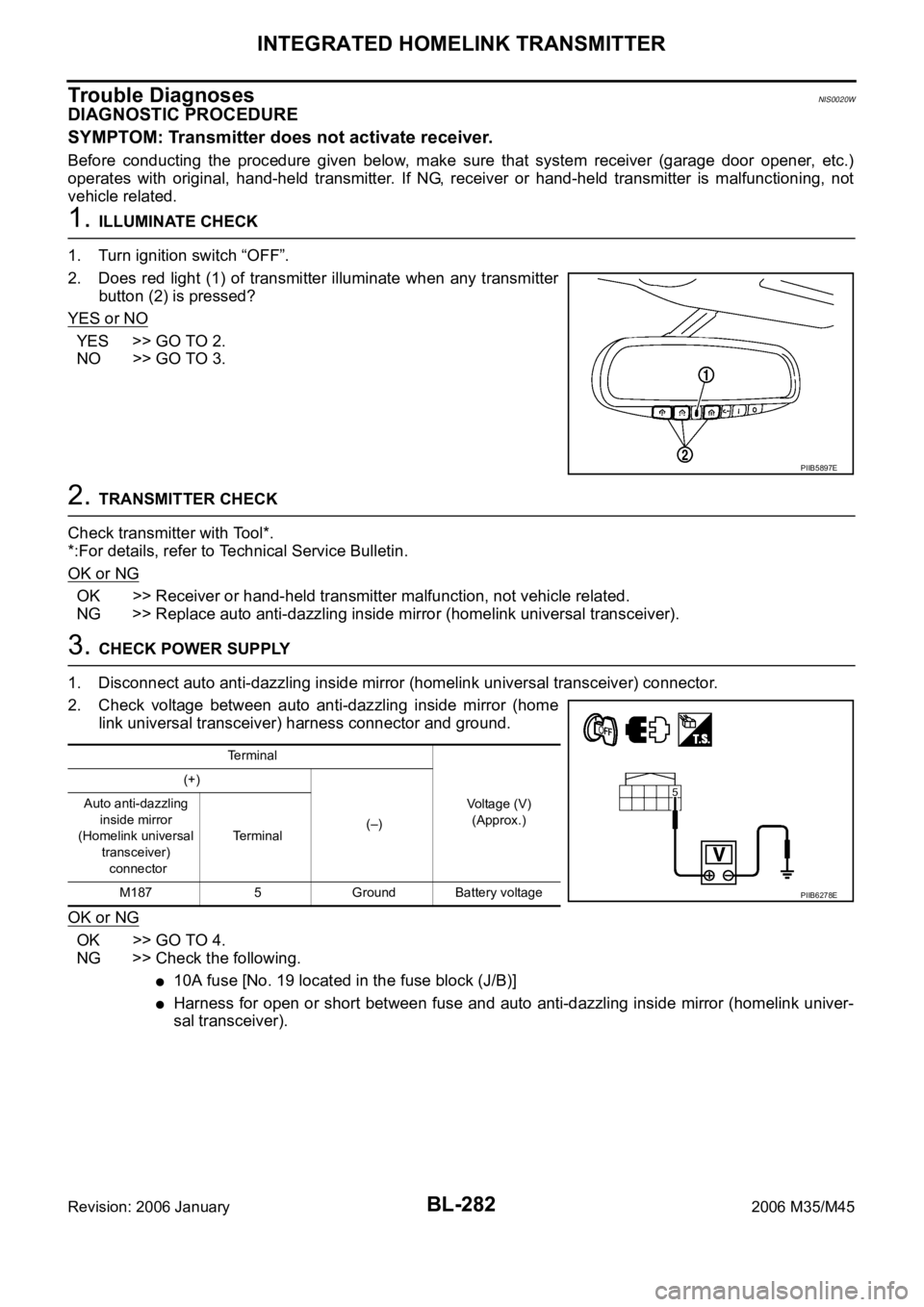
1. ILLUMINATE CHECK
1. Turn ignition switch “OFF”.
2. Does red light (1) of transmitter illuminate when any transmitter
button (2) is pressed?
YES or NO
YES >> GO TO 2.
NO >> GO TO 3.
2. TRANSMITTER CHECK
Check transmitter with Tool*.
*:For details, refer to Technical Service Bulletin.
OK or NG
OK >> Receiver or hand-held transmitter malfunction, not vehicle related.
NG >> Replace auto anti-dazzling inside mirror (homelink universal transceiver).
3. CHECK POWER SUPPLY
1. Disconnect auto anti-dazzling inside mirror (homelink universal transceiver) connector.
2. Check voltage between auto anti-dazzling inside mirror (home
link universal transceiver) harness connector and ground.
OK or NG
OK >> GO TO 4.
NG >> Check the following.
10A fuse [No. 19 located in the fuse block (J/B)]
Harness for open or short between fuse and auto anti-dazzling inside mirror (homelink univer-
sal transceiver).
PIIB5897E
Terminal
Voltage (V)
(Approx.) (+)
(–) Auto anti-dazzling
inside mirror
(Homelink universal
transceiver)
connectorTerminal
M187 5 Ground Battery voltage
PIIB6278E
Page 1435 of 5621

DI-2Revision: 2006 January2006 M35/M45 A/T INDICATOR ........................................................ 56
System Description ................................................. 56
MANUAL MODE .................................................. 56
NOT MANUAL MODE ......................................... 56
Wiring Diagram — AT/IND — ................................. 57
A/T Indicator Is Malfunction .................................... 59
WARNING CHIME .................................................. ... 60
System Description ................................................. 60
POWER SUPPLY AND GROUND CIRCUIT ....... 60
IGNITION KEY WARNING CHIME (WITH INTEL-
LIGENT KEY) ...................................................... 61
LIGHT WARNING CHIME ................................... 61
SEAT BELT WARNING CHIME ........................... 61
Component Parts and Harness Connector Location ... 62
Schematic ............................................................... 63
Wiring Diagram — CHIME — ................................. 64
Terminals and Reference Value for Combination
Meter ...................................................................... 67
Terminals and Reference Value for Unified Meter
and A/C Amp. ......................................................... 67
Terminals and Reference Value for BCM ................ 68
CONSULT-II Function (BCM) .................................. 69
CONSULT-II BASIC OPERATION ....................... 69
DATA MONITOR .................................................. 70
ACTIVE TEST ..................................................... 71
SELF-DIAG RESULTS ........................................ 71
CONSULT-II Function (METER A/C AMP) ............. 71
Trouble Diagnosis ................................................... 71
HOW TO PERFORM TROUBLE DIAGNOSIS .... 71
PRELIMINARY INSPECTION ............................. 71
SYMPTOM CHART ............................................. 72
Meter Buzzer Circuit Inspection .............................. 72
Lighting Switch Signal Inspection ........................... 73
Front Door Switch (Driver Side) Signal Inspection ... 73
Seat Belt Buckle Switch Signal Inspection ............. 74
Electrical Component Inspection ............................ 76
FRONT DOOR SWITCH (DRIVER SIDE) ........... 76
SEAT BELT BUCKLE SWITCH (DRIVER SIDE) ... 76
CAN COMMUNICATION ........................................... 77
System Description ................................................. 77
CAN Communication Unit ....................................... 77
LANE DEPARTURE WARNING SYSTEM ................ 78
Precautions for Lane Departure Warning (LDW)
system .................................................................... 78
System Description ................................................. 78
LDW SYSTEM OPERATION ............................... 78
POWER SUPPLY AND GROUND CIRCUIT ....... 80
Action Test ...........................................................
... 80
LDW SYSTEM RUNNING TEST ......................... 80
Camera Aiming Adjustment .................................... 81
OUTLINE ............................................................. 81
PREPARATION ................................................... 81TARGET SETTING .............................................. 81
VEHICLE HEIGHT CHECK ................................. 84
AIMING ADJUSTMENT ....................................... 84
Component Parts and Harness Connector Location ... 88
Wiring Diagram — LDW — ..................................... 89
Terminals and Reference Value for LDW Camera
Unit .......................................................................... 91
CONSULT-II Function (LDW) .................................. 91
DESCRIPTION .................................................... 91
CONSULT-II BASIC OPERATION ....................... 91
WORK SUPPORT ............................................... 92
SELF-DIAG RESULTS ......................................... 92
DATA MONITOR .................................................. 93
ACTIVE TEST ...................................................... 94
Trouble Diagnosis ................................................... 95
HOW TO PERFORM TROUBLE DIAGNOSIS .... 95
PRELIMINARY INSPECTION .............................. 95
SYMPTOM CHART .............................................. 96
Power Supply and Ground Circuit Inspection ......... 96
DTC [C1B00] CAMERA UNIT MALF ...................... 97
DTC [C1B01] CAM AIMING INCMP ....................... 97
DTC [C1B02] VHCL SPD DATA MALF ................... 97
DTC [C1B03] ABNRML TEMP DETECT ................ 97
DTC [U1000] CAN COMM CIRCUIT ...................... 98
DTC [U1010] CONTROL UNIT (CAN) .................... 98
LDW Chime Circuit Inspection ................................ 98
LDW Switch Circuit Inspection ................................ 99
LDW Indicator Lamp Circuit Inspection .................102
Turn Signal Input Inspection .................................103
Electrical Component Inspection ..........................103
LDW SWITCH ....................................................103
Removal and Installation for LDW Camera Unit ...103
REMOVAL ..........................................................103
INSTALLATION ..................................................103
Removal and Installation for LDW Chime .............104
REMOVAL ..........................................................104
INSTALLATION ..................................................104
Removal and Installation for LDW Switch .............104
COMPASS ...............................................................105
System Description ...............................................105
DIRECTION DISPLAY .......................................105
Zone Variation Change Procedure ........................105
Correction Functions of the Compass Display ......105
AUTOMATIC CORRECTION .............................105
MANUAL CORRECTION PROCEDURE ...........105
Wiring Diagram – COMPAS – ...............................106
Removal and Installation of Compass ...................107
CLOCK ....................................................................108
Wiring Diagram — CLOCK — ...............................108
Removal and Installation of Clock .........................109
REMOVAL ..........................................................109
INSTALLATION ..................................................109
Page 3010 of 5621

SQUEAK AND RATTLE TROUBLE DIAGNOSES
EI-5
C
D
E
F
G
H
J
K
L
MA
B
EI
Revision: 2006 January2006 M35/M45
SQUEAK AND RATTLE TROUBLE DIAGNOSESPFP:00000
Work FlowNIS0024A
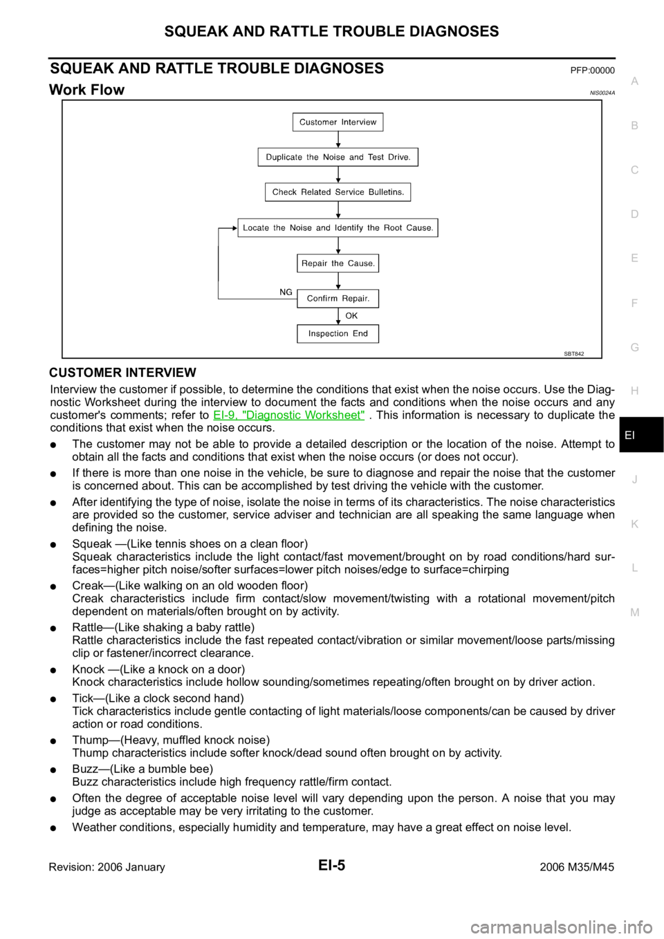
CUSTOMER INTERVIEW
Interview the customer if possible, to determine the conditions that exist when the noise occurs. Use the Diag-
nostic Worksheet during the interview to document the facts and conditions when the noise occurs and any
customer's comments; refer to EI-9, "
Diagnostic Worksheet" . This information is necessary to duplicate the
conditions that exist when the noise occurs.
The customer may not be able to provide a detailed description or the location of the noise. Attempt to
obtain all the facts and conditions that exist when the noise occurs (or does not occur).
If there is more than one noise in the vehicle, be sure to diagnose and repair the noise that the customer
is concerned about. This can be accomplished by test driving the vehicle with the customer.
After identifying the type of noise, isolate the noise in terms of its characteristics. The noise characteristics
are provided so the customer, service adviser and technician are all speaking the same language when
defining the noise.
Squeak —(Like tennis shoes on a clean floor)
Squeak characteristics include the light contact/fast movement/brought on by road conditions/hard sur-
faces=higher pitch noise/softer surfaces=lower pitch noises/edge to surface=chirping
Creak—(Like walking on an old wooden floor)
Creak characteristics include firm contact/slow movement/twisting with a rotational movement/pitch
dependent on materials/often brought on by activity.
Rattle—(Like shaking a baby rattle)
Rattle characteristics include the fast repeated contact/vibration or similar movement/loose parts/missing
clip or fastener/incorrect clearance.
Knock —(Like a knock on a door)
Knock characteristics include hollow sounding/sometimes repeating/often brought on by driver action.
Tick—(Like a clock second hand)
Tick characteristics include gentle contacting of light materials/loose components/can be caused by driver
action or road conditions.
Thump—(Heavy, muffled knock noise)
Thump characteristics include softer knock/dead sound often brought on by activity.
Buzz—(Like a bumble bee)
Buzz characteristics include high frequency rattle/firm contact.
Often the degree of acceptable noise level will vary depending upon the person. A noise that you may
judge as acceptable may be very irritating to the customer.
Weather conditions, especially humidity and temperature, may have a great effect on noise level.
SBT842