Page 1137 of 5621
BL-198
FRONT DOOR LOCK
Revision: 2006 January2006 M35/M45
11. Remove the front gasket and rear gasket.
12. Remove the TORX bolts (T30), remove the door lock assembly.
13. Remove the TORX bolt (T30) of the outside handle bracket.
14. While pulling outside handle bracket, slide toward rear of vehicle
to remove outside handle bracket.
15. Disconnect the door lock actuator connector and remove the door lock assembly.
PIIB5811E
PIIB5812E
PIIB5813E
PIIB5814E
Page 1138 of 5621
FRONT DOOR LOCK
BL-199
C
D
E
F
G
H
J
K
L
MA
B
BL
Revision: 2006 January2006 M35/M45
16. Reach to separate the outside handle cable connection.
INSTALLATION
Install in the reverse order of removal.
CAUTION:
To install each rod, be sure to rotate the rod holder until a click is felt.
PIIB5815E
Page 1139 of 5621
BL-200
REAR DOOR LOCK
Revision: 2006 January2006 M35/M45
REAR DOOR LOCKPFP:82502
Component StructureNIS001ZF
Removal and InstallationNIS001ZG
REMOVAL
1. Remove the rear door finisher. Refer toEI-34, "Removal and Installation" .
2. Disconnect the inside handle knob cable and lock knob cable
from the back side of the rear door finisher.
3. Remove the rear door sash. Refer toGW-67, "
REAR DOOR GLASS AND REGULATOR" .
4. Remove the rear door window and rear door screen assembly. Refer toGW-67, "
REAR DOOR GLASS
AND REGULATOR" .
5. Remove door side grommet, and remove outside handle escutcheon bolt (TORX T30) from grommet
hole.
1. Outside handle 2. Front gasket 3. Inside handle
4. Lock knob cable 5. Inside handle knob cable 6. Door lock assembly
7. Outside handle cable 8. Outside handle bracket 9. Grommet
10. Rear gasket 11. Outside handle escutcheon
PIIB5816E
PIIB4933E
Page 1140 of 5621
REAR DOOR LOCK
BL-201
C
D
E
F
G
H
J
K
L
MA
B
BL
Revision: 2006 January2006 M35/M45
CAUTION:
Do not forcibly remove the TORX bolts (T30).
6. While pulling the outside handle, remove outside handle
escutcheon.
7. While pulling outside handle, slide toward rear of vehicle to
remove outside handle.
8. Remove the front gasket and rear gasket.
PIIB5808E
PIIB5809E
PIIB5810E
PIIB5811E
Page 1141 of 5621
BL-202
REAR DOOR LOCK
Revision: 2006 January2006 M35/M45
9. Remove the TORX bolts (T30), remove the door lock assembly.
10. Remove the TORX bolt (T30), and remove the outside handle
bracket.
11. While pulling outside handle, slide toward rear of vehicle to
remove outside handle.
12. Disconnect the door lock actuator connector and remove the door lock assembly.
13. Reach to separate outside handle cable connection.
INSTALLATION
Install in the reverse order of removal.
CAUTION:
To install each rod, be sure to rotate the rod holder until a click is felt.
PIIB5812E
PIIB5813E
PIIB5814E
PIIB5815E
Page 1160 of 5621

VEHICLE SECURITY (THEFT WARNING) SYSTEM
BL-221
C
D
E
F
G
H
J
K
L
MA
B
BL
Revision: 2006 January2006 M35/M45
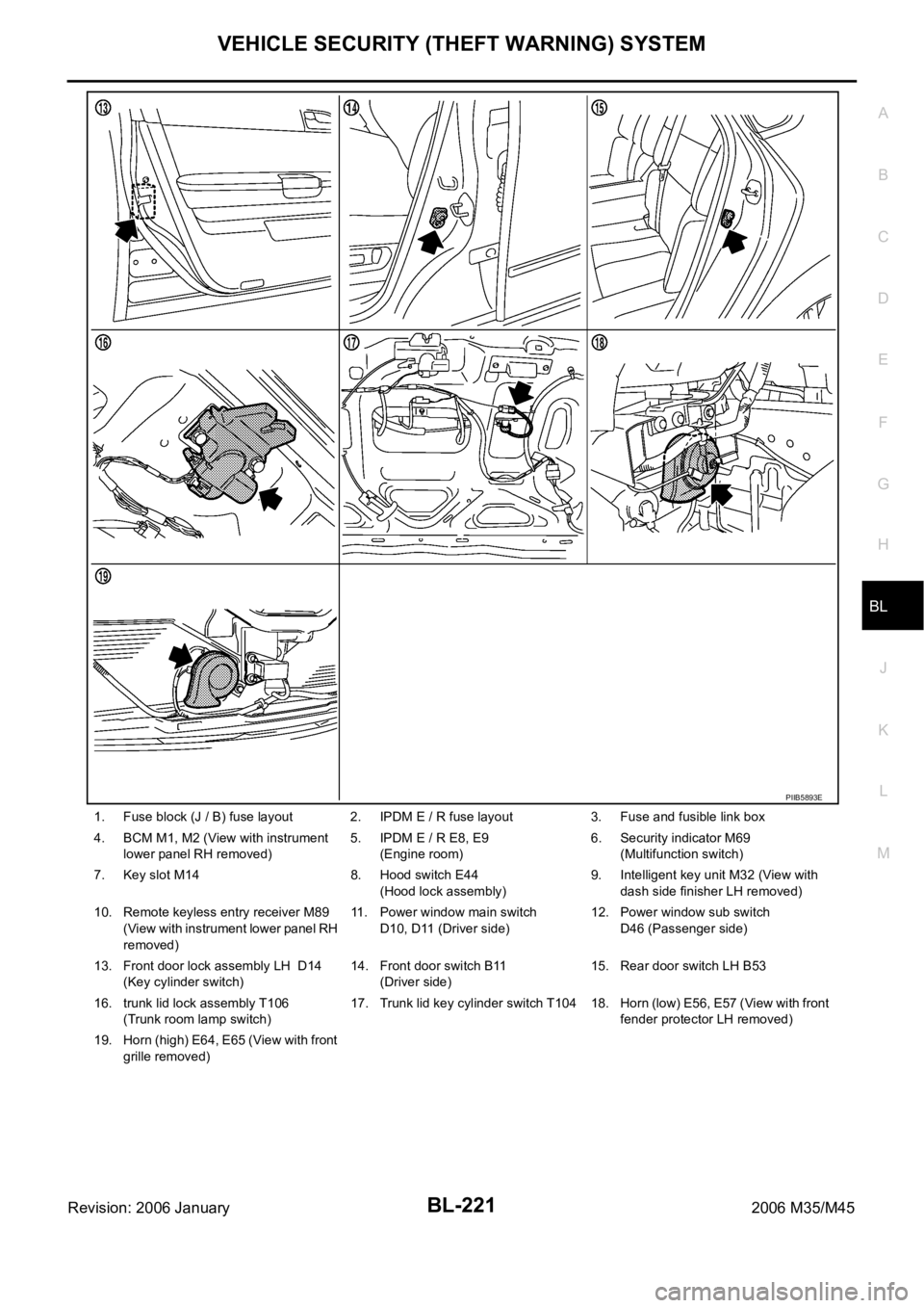
1. Fuse block (J / B) fuse layout 2. IPDM E / R fuse layout 3. Fuse and fusible link box
4. BCM M1, M2 (View with instrument
lower panel RH removed)5. IPDM E / R E8, E9
(Engine room)6. Security indicator M69
(Multifunction switch)
7. Key slot M14 8. Hood switch E44
(Hood lock assembly)9. Intelligent key unit M32 (View with
dash side finisher LH removed)
10. Remote keyless entry receiver M89
(View with instrument lower panel RH
removed)11. Power window main switch
D10, D11 (Driver side)12. Power window sub switch
D46 (Passenger side)
13. Front door lock assembly LH D14
(Key cylinder switch)14. Front door switch B11
(Driver side)15. Rear door switch LH B53
16. trunk lid lock assembly T106
(Trunk room lamp switch)17. Trunk lid key cylinder switch T104 18. Horn (low) E56, E57 (View with front
fender protector LH removed)
19. Horn (high) E64, E65 (View with front
grille removed)
PIIB5893E
Page 1161 of 5621

BL-222
VEHICLE SECURITY (THEFT WARNING) SYSTEM
Revision: 2006 January2006 M35/M45
System DescriptionNIS001ZU
DESCRIPTION
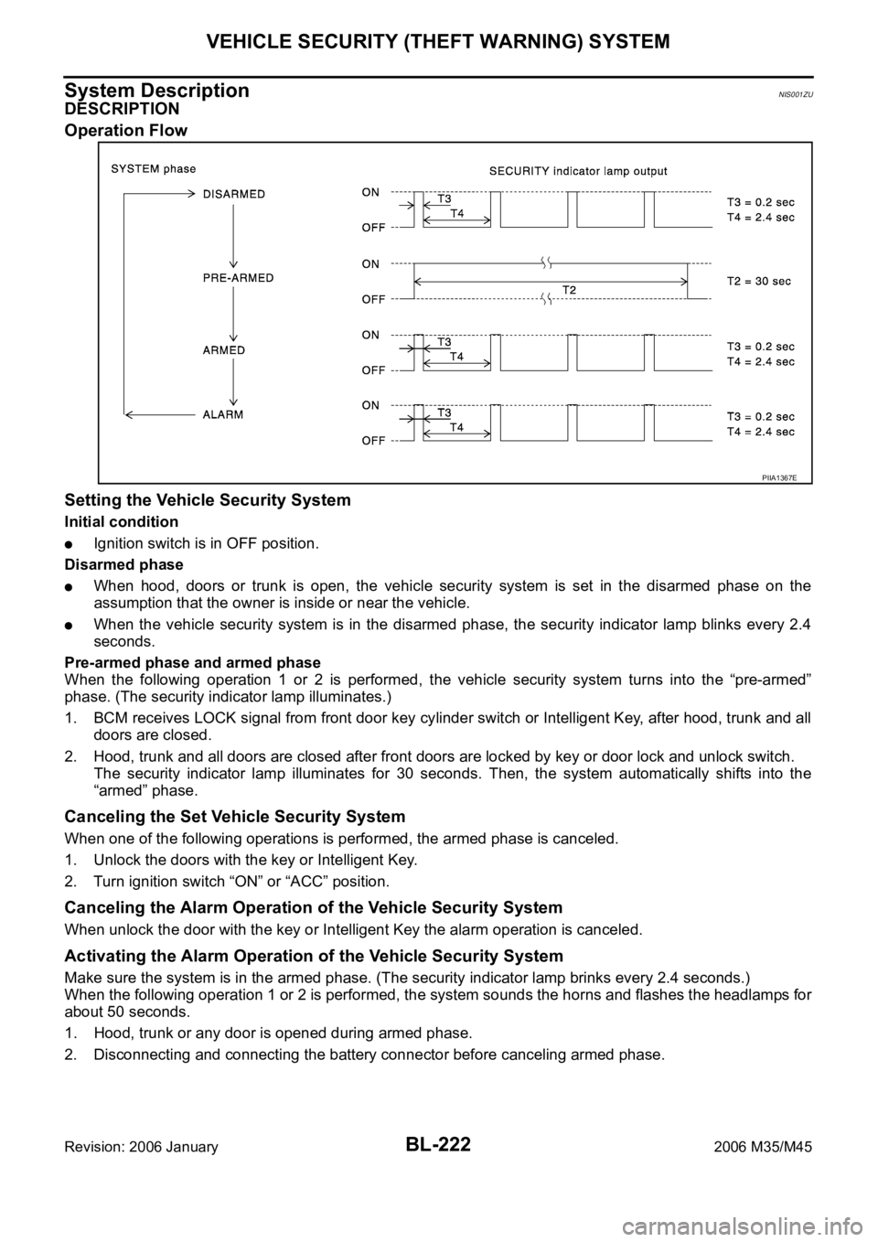
Operation Flow
Setting the Vehicle Security System
Initial condition
Ignition switch is in OFF position.
Disarmed phase
When hood, doors or trunk is open, the vehicle security system is set in the disarmed phase on the
assumption that the owner is inside or near the vehicle.
When the vehicle security system is in the disarmed phase, the security indicator lamp blinks every 2.4
seconds.
Pre-armed phase and armed phase
When the following operation 1 or 2 is performed, the vehicle security system turns into the “pre-armed”
phase. (The security indicator lamp illuminates.)
1. BCM receives LOCK signal from front door key cylinder switch or Intelligent Key, after hood, trunk and all
doors are closed.
2. Hood, trunk and all doors are closed after front doors are locked by key or door lock and unlock switch.
The security indicator lamp illuminates for 30 seconds. Then, the system automatically shifts into the
“armed” phase.
Canceling the Set Vehicle Security System
When one of the following operations is performed, the armed phase is canceled.
1. Unlock the doors with the key or Intelligent Key.
2. Turn ignition switch “ON” or “ACC” position.
Canceling the Alarm Operation of the Vehicle Security System
When unlock the door with the key or Intelligent Key the alarm operation is canceled.
Activating the Alarm Operation of the Vehicle Security System
Make sure the system is in the armed phase. (The security indicator lamp brinks every 2.4 seconds.)
When the following operation 1 or 2 is performed, the system sounds the horns and flashes the headlamps for
about 50 seconds.
1. Hood, trunk or any door is opened during armed phase.
2. Disconnecting and connecting the battery connector before canceling armed phase.
PIIA1367E
Page 1162 of 5621

VEHICLE SECURITY (THEFT WARNING) SYSTEM
BL-223
C
D
E
F
G
H
J
K
L
MA
B
BL
Revision: 2006 January2006 M35/M45
POWER SUPPLY AND GROUND CIRCUIT
Power is supplied at all times
through 50A fusible link (letter F , located in the fuse and fusible link box)
to BCM terminal 55,
through 10A fuse [No. 21, located in the fuse block (J/B)]
to BCM terminal 42,
through 10A fuse [No. 71, located in the IPDM E/R]
to IPDM E/R internal CPU,
through 15A fuse [No. 78, located in the IPDM E/R]
to IPDM E/R internal CPU,
through 15A fuse [No. 37, located in the fuse block (J/B)]
to multi-function switch (security indicator) terminal 1.
With the ignition switch in the ACC or ON position, power is supplied
through 10A fuse [No. 6, located in the fuse block (J/B)]
to BCM terminal 11.
Ground is supplied
to BCM terminal 52
through body grounds M16 and M70.
INITIAL CONDITION TO ACTIVATE THE SYSTEM
The operation of the vehicle security system is controlled by the doors, hood and trunk.
To activate the vehicle security system, BCM must receive signals indicating the doors, hood and trunk are
closed and the doors are locked by key fob.
When a door is open, terminal 12 (passenger side door), 13 (rear RH door), 62 (driver side door), 63 (rear LH
door) receives a ground signal from each door switch.
When front door LH is unlocked by power window main switch (door lock and unlock switch), BCM terminal 22
receives an unlock signal from terminal 14 of power window main switch with power window serial link.
When front door RH is unlocked by power window sub-switch (passenger side) (door lock and unlock switch),
BCM terminal 22 receives an unlock signal from terminal 16 of power window sub-switch (passenger side)
with power window serial link.
When front door key cylinder switch is in LOCK position, ground is supplied
to power window main switch terminal 4
through front door key cylinder switch terminals 6 and 4
through body grounds M16 and M70.
When the hood is open, IPDM E/R receives a ground signal
to IPDM E/R terminal 60
through hood switch terminal 2
through hood switch terminal 1
through body grounds E22, and E43.
The IPDM E/R then sends a signal to BCM via CAN communication line.
When the trunk is open, ground is supplied
to BCM terminal 57
through trunk room lamp switch terminal 1
through trunk room lamp switch terminal 2
through body grounds B5, B40 and B131.